Inventek Systems ISM43907-L170-EVB User manual

ISM43907-L170-EVB User’s Manual
DOC-907UM-2017-1.0 Confidential Inventek Systems
Page 2
Table of Contents
1PART NUMBER DETAIL DESCRIPTION.......................................................................... 3
1.1 Ordering Information...................................................................................................... 3
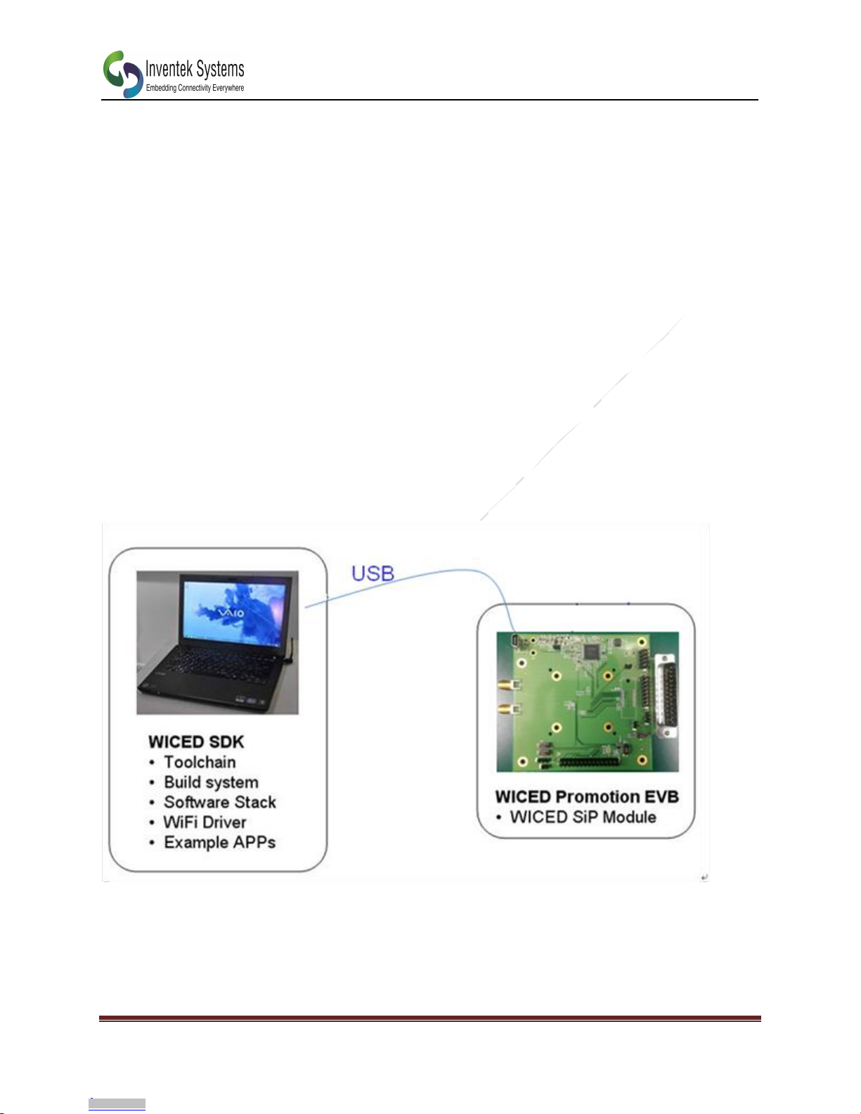
2OVERVIEW........................................................................................................................... 3
3FEATURES ............................................................................................................................ 4
3.1 Limitations...................................................................................................................... 4
4ISM43907 EVB USER’s MANUAL OVERIVEW ............................................................... 5
4.1 Overview:........................................................................................................................ 5
4.2 Antenna Options ............................................................................................................. 5
5ISM43907 EVALUATION BOARD INTRODUCTION...................................................... 6
6ISM43907 EVALUATION BOARD FEATURES................................................................ 7
6.1 Feature List ..................................................................................................................... 7
The ISM43907-L170-EVB provides a platform for the design and development of applications
that run on a ISM43907-L170 SiP.................................................................................................. 7
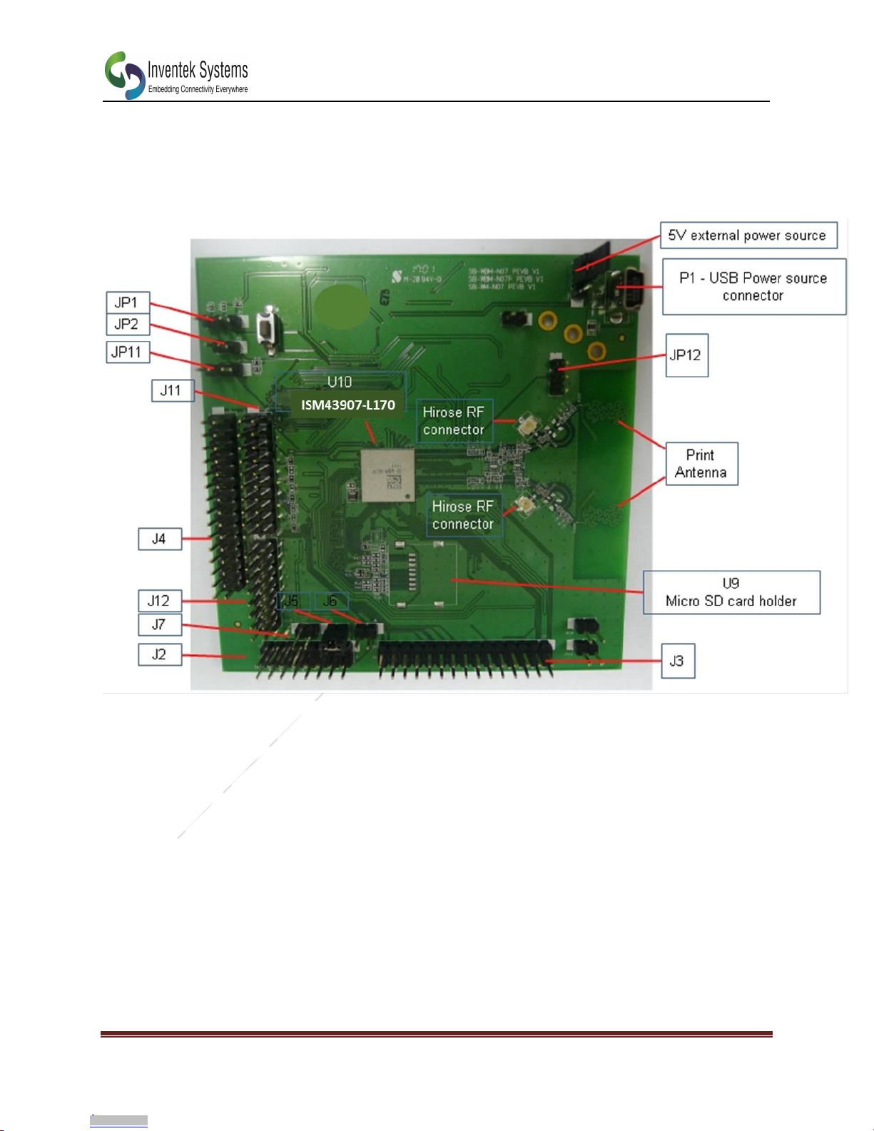
7ISM43907 EVALUATION BOARD HW LAYOUT & CONFIGURATION ...................... 8
7.1 ISM43907-L170-EVB Diagram ..................................................................................... 8
7.2 ISM43907-L170-EVB HW Interface Layout Placement ............................................. 10
7.2.1 Bottom View............................................................................................................. 11
8POWER SUPPLY................................................................................................................. 12
8.1 Power source................................................................................................................. 12
8.2 Reset source.................................................................................................................. 12
8.3 Audio............................................................................................................................. 12
8.4 UART............................................................................................................................ 12
8.5 PWM............................................................................................................................. 12
8.6 I2C................................................................................................................................. 12
8.7 SPI................................................................................................................................. 13
8.8 GPIO............................................................................................................................. 13
9SCHEMATICS..................................................................................................................... 18
9.1 Application schematic................................................................................................... 18
9.1.1 Power Schematic....................................................................................................... 19
9.1.2 USB to URAT, JTAG,& Reset................................................................................. 20
9.1.3 External Flash ........................................................................................................... 21
9.1.4 I/O............................................................................................................................. 22
10 REVISION CONTROL........................................................................................................ 23
11 CONTACT INFORMATION............................................................................................... 23
Downloaded from Arrow.com.Downloaded from Arrow.com.

ISM43907-L170-EVB User’s Manual
DOC-907UM-2017-1.0 Confidential Inventek Systems
Page 3
1 PART NUMBER DETAIL DESCRIPTION
1.1 Ordering Information
Device
Description
Ordering Number
ISM43907-L170
2.4/5G Wi-Fi SiP Module
ISM43907-L170
ISM43907-L170-EVB
2.4/5G Wi-Fi SiP EVB,
SDIO I/F Evaluation Board
ISM43907-L170-EVB
2 OVERVIEW
The Inventek ISM43907 single-chip Dual Band, 2.4G/5G (802.11a/b/g/n). radio device provides
the highest level of integration for a wireless system, with integrated dual band Wi-Fi based on
Cypress’ IEEE802.11 a/b/g/n single-stream with support for antenna diversity and provisions for
supporting future specifications. Thus, the ISM43907 can be used to enable wireless connectivity
to the simplest existing sensor products with minimal engineering effort. The ISM43907 also
includes integrated power amplifiers, LNAs and T/R switches for the 2.4 GHz and 5 GHz WLAN
bands, greatly reducing the external part count, PCB footprint, and cost of the solution. The
ISM43907 also integrates an embedded ARM CortexTM-R4 MCU, clock, and front end with the
Dual Band radio.
The ISM43907 is provided in the smallest LGA form-factor solution with minimal external
components to drive down cost for massvolumes and allows for handhelddevice flexibilityin size,
form and function. Comprehensive power management circuitry and software ensure the system
can meet the needs of high mobile devices that require minimal power consumption and reliable
operations.
The ISM43907 also enables coexistence support for external radios such as cellular and LTE,
GPS, and Ultra-Wideband. For the WLAN section, the host interface is a SDIO v2.0 interface.
The ISM43907 is a complete WiFi & MCU SiP which is designed for embedded wireless
solution and a cost-effective, low power capabilities high performance MCU in M2M
applications.
The ISM43907 includes standards-based wireless technologies to enable IP infrastructures for
smart grid, smart home, security, building automation, toys, robots, remote health and wellness
monitoring and other M2M and IoT applications.
The ISM43907 enables customers to reduce development time, lower manufacturing costs,
save board space, ease certification, and minimize RF expertise required. Additionally, the
ISM43907 is provided as a complete platform solution including software drivers, sample
applications, API guide, user documentation and a world-class support community from
Broadcom WICED Platform.
Downloaded from Arrow.com.Downloaded from Arrow.com.Downloaded from Arrow.com.

ISM43907-L170-EVB User’s Manual
DOC-907UM-2017-1.0 Confidential Inventek Systems
Page 4
3 FEATURES
The ISM43907 supports the following WLAN functions:
Dual-band 2.4 GHz and 5 GHz IEEE 802.11 a/b/g/n Frequency Band
IEEE802.11 a / b / g / n (single-stream), dual-band radio with internal Power Amplifiers,
LNAs and T/R switches
On-chip WLAN driver execution capable of supporting IEEE 802.11 functionality
Single and dual-antenna support
WLAN host interface :
oSDIO v2.0, including default and high-speed timing.
ARM 32-bit CortexTM-R4 embedded processor
SPI, UART serial interface options
JTAG debug interface
2MB of application SRAM, 640KB of ROM containing WICED SDK
Sensor applications support with ADC, I2C, I2S, GPIO, USB, PWM
Single-chip MAC/BB/RF On-chip functionality
Modulation Modes: WiFi: CCK and OFDM with BPSK, QPSK, 16 QAM, 64QAM
Hardware Encryption: WEP, WPA/WPA2
Supported Data Rates:
oIEEE 802.11b 1 –11 Mbps
oIEEE 802.11a 6 –54 Mbps
oIEEE 802.11g 6 –54 Mbps
oIEEE 802.11n (2.4 GHz & 5GHz) 7.2 –150Mbps
Advanced 1x1 802.11n features:
oFull/Half Guard Interval
oFrame Aggregation
oSpace Time Block Coding (STBC)
oLow Density Parity Check (LDPC) Encoding
Two antenna configurations supporting antenna diversity.
WICED Fully compatible
MSL level 3
Supports BT/BLE COEX
Operating Temperature: -40C to +85C
RoHS compliant
Pb-Free
3.1 Limitations
Inventek Systems products are not authorized for use in safety-critical applications
(such as life support) where a failure of the Inventek Systems product would
reasonably be expected to cause severe personal injury or death.
Downloaded from Arrow.com.Downloaded from Arrow.com.Downloaded from Arrow.com.Downloaded from Arrow.com.

ISM43907-L170-EVB User’s Manual
DOC-907UM-2017-1.0 Confidential Inventek Systems
Page 5
4 ISM43907 EVB USER’s MANUAL OVERIVEW
4.1 Overview:
This document provides information describing the ISM43907-L170-EVB (Evaluation
Board), development platform.
The ISM43907-L170-EVB User’s Manual is intended for engineers planning to use the
Inventek ISM43907-L170-EVB in order to utilize and evaluate the Inventek ISM43907-
L170 SiP radio.
4.2 Antenna Options
RF Test ports include U.Fl RF connector
oHIROSE U.FL RF connector, part number U.FL-R-SMT-1 (10)
oAll boards are currently configured to use connector J38 with an external antenna
PCB Etched Antenna
oThe PCB etched antenna (ANT4) can be used by removing C104 and placing an
8.2pF capacitor in location C103.
External Antenna
oThe Inventek W2.4-5P-U dual band PCB antenna is included with the EVB
oMore information on this antenna, please visit:
http://www.inventeksys.com/products-page/wifi-antennas/wi-fi-2-4-5ghz/
Downloaded from Arrow.com.Downloaded from Arrow.com.Downloaded from Arrow.com.Downloaded from Arrow.com.Downloaded from Arrow.com.

ISM43907-L170-EVB User’s Manual
DOC-907UM-2017-1.0 Confidential Inventek Systems
Page 6
5 ISM43907 EVALUATION BOARD INTRODUCTION
5.1 Introduction
ISM43907-L170-EVB Development System
The ISM43907-L170 SiP radio is a development system that facilitates Wireless Internet
Connectivity for Embedded Devices.
The ISM43907-L170-EVB development system, shown in Figure 1, is comprised of:
•A software Development Kit with a tool chain and build system, a WiFi driver and software
stack together with example applications. The SDK runs on a Windows or Linux PC.
•A EVB. Applications developed using the WICED SDK is downloaded via USB to the Inventek
ISM43907-L170 SiP on the ISM43907-L170-EVB Board. The ISM43907-L170 SiP consists of a
Broadcom IEEE802.11 a/b/g/n WiFi chip and high-performance ARM CortexTM-R4 32-bit
microcontroller.
Downloaded from Arrow.com.Downloaded from Arrow.com.Downloaded from Arrow.com.Downloaded from Arrow.com.Downloaded from Arrow.com.Downloaded from Arrow.com.

ISM43907-L170-EVB User’s Manual
DOC-907UM-2017-1.0 Confidential Inventek Systems
Page 7
6 ISM43907 EVALUATION BOARD FEATURES
6.1 Feature List
The ISM43907-L170-EVB provides a platform for the design and development of applications
that run on a ISM43907-L170 SiP.
Features
Detail
ISM43907-L170 SiP
The ISM43907-L170 SiP includes and Cypress host microprocessor, and Cypress WiFi Chip
-Cypress Microprocessor:
ARM-based 32-bit , 2MB of application SRAM, 640KB of ROM containing WICED SDK.
-Wi-FI SoC
IEEE802.11 a/b/g/n
ISM43907-L170-EVB
The ISM43907-L170-EVB is a complete WiFi networking solution and includes t h e
ISM43907-L170 SiP, RF SMA connector and power supply
Program & Debug
Interface
Applications are downloaded to the Cypress R4 embedded host and debugged using
either the USB or the JTAG interface
USB-Serial UART
Interface
A UART on the host microprocessor connects to the EVB USB-serial interface to enable
serial communications with a PC terminal application
Expansion Header
The expansion header facilitates custom sensor interfaces and expansion boards
Reset Switch
Enable manual reset of the MCU
Power Supply
The EVB may be powered directly from the USB interface or from an external +5V
power supply.
Downloaded from Arrow.com.Downloaded from Arrow.com.Downloaded from Arrow.com.Downloaded from Arrow.com.Downloaded from Arrow.com.Downloaded from Arrow.com.Downloaded from Arrow.com.

ISM43907-L170-EVB User’s Manual
DOC-907UM-2017-1.0 Confidential Inventek Systems
Page 8
7 ISM43907 EVALUATION BOARD HW LAYOUT &
CONFIGURATION
7.1 ISM43907-L170-EVB Diagram
Downloaded from Arrow.com.Downloaded from Arrow.com.Downloaded from Arrow.com.Downloaded from Arrow.com.Downloaded from Arrow.com.Downloaded from Arrow.com.Downloaded from Arrow.com.Downloaded from Arrow.com.

ISM43907-L170-EVB User’s Manual
DOC-907UM-2017-1.0 Confidential Inventek Systems
Page 9
7.2 ISM43907-L170 Block Diagram
ISM43907-L170-EVB Diagram
Downloaded from Arrow.com.Downloaded from Arrow.com.Downloaded from Arrow.com.Downloaded from Arrow.com.Downloaded from Arrow.com.Downloaded from Arrow.com.Downloaded from Arrow.com.Downloaded from Arrow.com.Downloaded from Arrow.com.

ISM43907-L170-EVB User’s Manual
DOC-907UM-2017-1.0 Confidential Inventek Systems
Page 10
7.2 ISM43907-L170-EVB HW Interface Layout Placement
7.2.1 Top View
Downloaded from Arrow.com.Downloaded from Arrow.com.Downloaded from Arrow.com.Downloaded from Arrow.com.Downloaded from Arrow.com.Downloaded from Arrow.com.Downloaded from Arrow.com.Downloaded from Arrow.com.Downloaded from Arrow.com.Downloaded from Arrow.com.

ISM43907-L170-EVB User’s Manual
DOC-907UM-2017-1.0 Confidential Inventek Systems
Page 11
7.2.1 Bottom View
Downloaded from Arrow.com.Downloaded from Arrow.com.Downloaded from Arrow.com.Downloaded from Arrow.com.Downloaded from Arrow.com.Downloaded from Arrow.com.Downloaded from Arrow.com.Downloaded from Arrow.com.Downloaded from Arrow.com.Downloaded from Arrow.com.Downloaded from Arrow.com.

ISM43907-L170-EVB User’s Manual
DOC-907UM-2017-1.0 Confidential Inventek Systems
Page 12
8 POWER SUPPLY
8.1 Power source
The ISM43907-L170-EVB is designed to be powered by a 5 V DC power supply.
It is possible to configure the evaluation board to use any of following two sources for the power
supply:
•5 V External power source hole on the board. The JP4 need connect Pin1 and pin2
•5 V DC power with 500 mA limitation from P1, the USB Micro-AB connecter, The JP4 need
connect Pin2 and pin3
8.2 Reset source
The reset signal of the ISM43907-L170-EVB board is low active and the reset source includes:
•Reset button SW1.
8.3 Audio
The ISM43907-L170-EVB board enables two channels of I2S function, one channel is
connection to header (J4) and another is connection to header (J3).
8.4 UART
The ISM43907-L170-EVB board enables one fast channel of UART and two slow channels of
UART communication. Fast UART is connect to Header J12 (Pin8, pin 10, pin12, and pin14).
1st channel of slow UART (UART1) connects to R6, R8 & U1 (USB to UART IC), and Header J4
(Pin17, Pin19). 2nd Channel of slow UART connects to header J4 (Pin23 & Pin25).
8.5 PWM
The ISM43907-L170-EVB board enables PWM control signal and connects to header J4.
8.6 I2C
The ISM43907-L170-EVB board enables two channels of I2C function. One channel connects to
J3 (Pin26 & Pin28). Another channel connects to J3 (pin27 & Pin29).
•I2C signal traces need to pull high.
Downloaded from Arrow.com.Downloaded from Arrow.com.Downloaded from Arrow.com.Downloaded from Arrow.com.Downloaded from Arrow.com.Downloaded from Arrow.com.Downloaded from Arrow.com.Downloaded from Arrow.com.Downloaded from Arrow.com.Downloaded from Arrow.com.Downloaded from Arrow.com.Downloaded from Arrow.com.

ISM43907-L170-EVB User’s Manual
DOC-907UM-2017-1.0 Confidential Inventek Systems
Page 13
8.7 SPI
The ISM43907-L170-EVB board enables two channels of SPI function. The First channel
connects to J3 ((Pin16, Pin18, Pin20, & Pin22). The Second channel connects to J3 (Pin1, Pin3,
Pin5, & Pin7).
8.8 GPIO
The ISM43907-L170-EVB board release GPIO function.
The function is connecting to J2.
9.0 CONNECTORS
9.1 Power Supply Connector (Micro USB: P1)
The ISM43907-L170-EVB board can be powered from 5V DC power supply via the external Mini
USB connector (P1) or external power supply hole.
-Micro USB Connector (P1)
Pin
Description
Pin
Description
1
VBUS (5V)
4
NC
2
D- (connect to U1 pin 7)
5
GND
3
D+(connect to U1 pin 8)
Front View
9.2 Functional Pin Header
The ISM43907-L170-EVB board enables I2S, I2C, SPI, UART, PWM, BT_ADC, GPIO
function.
Downloaded from Arrow.com.Downloaded from Arrow.com.Downloaded from Arrow.com.Downloaded from Arrow.com.Downloaded from Arrow.com.Downloaded from Arrow.com.Downloaded from Arrow.com.Downloaded from Arrow.com.Downloaded from Arrow.com.Downloaded from Arrow.com.Downloaded from Arrow.com.Downloaded from Arrow.com.Downloaded from Arrow.com.

ISM43907-L170-EVB User’s Manual
DOC-907UM-2017-1.0 Confidential Inventek Systems
Page 14
Pin
Description
Pin
Description
1
NC
2
GPIO_13_SDIO_MODE
3
NC
4
GPIO_12_CODEC_PDN
5
NC
6
GPIO_11_ACPU_BOOT_MODE
7
NC
8
GPIO10_DEEP_RST
9
NC
10
GPIO_9_USB_SEL
11
GPIO_16_USB_EN_AUD_SW
12
GPIO_7_WCPU_BOOT_MODE
13
GPIO_15
14
GPIO_1_GSPI_MODE
15
GPIO_14
16
GPIO_0_USB_CLT
-
J3
Pin
Description
Pin
Description
1
SPI_1_CS
2
SFLASH_MOSI_3
3
SPI_1_MOSI
4
SFLASH_MOSI_2
5
SPI_1_MISO
6
SFLASH_MOSI_1
7
SPI_1_CLK
8
SFLASH_MOSI_0
9
GND
10
SFLASH_CSN
11
I2S1_SD_OUT
12
SFLASH_CLK
13
I2S1_SD_IN_C
14
GND
15
GND
16
SPI_0_CS
17
I2S1_MCK
18
SPI_0_MOSI
19
GND
20
SPI_0_MISO
21
I2S1_WS_LRCK
22
SPI_0_CLK
23
I2S1_SCK_BCLK
24
GND
25
GND
26
I2C_1_SCL
27
I2C_0_SCL
28
I2C_1_SDA
29
I2C_0_SDA
30
GND
Downloaded from Arrow.com.Downloaded from Arrow.com.Downloaded from Arrow.com.Downloaded from Arrow.com.Downloaded from Arrow.com.Downloaded from Arrow.com.Downloaded from Arrow.com.Downloaded from Arrow.com.Downloaded from Arrow.com.Downloaded from Arrow.com.Downloaded from Arrow.com.Downloaded from Arrow.com.Downloaded from Arrow.com.Downloaded from Arrow.com.

ISM43907-L170-EVB User’s Manual
DOC-907UM-2017-1.0 Confidential Inventek Systems
Page 15
J4
Pin
Description
Pin
Description
1
USB2_HOST_DEV_SEL
2
PWM_5
3
GND
4
PWM_4
5
HIB_WAKE
6
PWM_3
7
HIB_REG_ON_IN
8
PWM_2
9
HIB_LPO_SEL
10
PWM_1
11
GND
12
PWM_0
13
RF_GPAIO_OUT
14
GND
15
GND
16
I2S0_SD_OUT
17
RF_SW_CTRL_7_UART_TX_OUT
18
I2S0_SD_IN_C
19
RF_SW_CTRL_6_UART_RX_IN
20
GND
21
GND
22
I2S0_MCK
23
RF_SW_CTRL_9_BT_SEC_OUT
24
GND
25
RF_SW_CTRL_8_BT_SEC_IN
26
I2S0_WS_LRCK
27
GND
28
GND
29
GND
30
I2S0_SCK_BCLK
J12
Pin
Description
Pin
Description
1
USB2_DP
2
ANT1_DIV_RF_SW_CTRL_5
3
USB2_DN
4
ANT0_DIV_RF_SW_CTRL_4
5
PULL HIGH
6
NC
7
GND
8
UART0_CTS_IN
9
GND
10
UART0_RTS_OUT
11
GND
12
UART0_RXD_IN
13
GND
14
UART0_TXD_OUT
15
GND
16
NC
Downloaded from Arrow.com.Downloaded from Arrow.com.Downloaded from Arrow.com.Downloaded from Arrow.com.Downloaded from Arrow.com.Downloaded from Arrow.com.Downloaded from Arrow.com.Downloaded from Arrow.com.Downloaded from Arrow.com.Downloaded from Arrow.com.Downloaded from Arrow.com.Downloaded from Arrow.com.Downloaded from Arrow.com.Downloaded from Arrow.com.Downloaded from Arrow.com.

ISM43907-L170-EVB User’s Manual
DOC-907UM-2017-1.0 Confidential Inventek Systems
Page 16
J11
Pin
Description
Pin
Description
1
GPIO_2_JTAG_TCK
2
GND
3
GPIO_3_JTAG_TMS
4
NC
5
GPIO_4_JTAG_TDI
6
NC
7
GPIO_5_JTAG_TDO
8
NC
9
GPIO_6_JTAG_TRST
10
NC
11
NC
12
NC
13
NC
14
NC
15
NC
16
GND
17
GND
18
NC
19
NC
20
NC
-JP4 -JP11
Pin
Description
1
EXT_5V
2
5V_Input
3
VDD_5V-USB
Pin
Description
1
VDDIO
2
JTAG_SEL
3
GND
Downloaded from Arrow.com.Downloaded from Arrow.com.Downloaded from Arrow.com.Downloaded from Arrow.com.Downloaded from Arrow.com.Downloaded from Arrow.com.Downloaded from Arrow.com.Downloaded from Arrow.com.Downloaded from Arrow.com.Downloaded from Arrow.com.Downloaded from Arrow.com.Downloaded from Arrow.com.Downloaded from Arrow.com.Downloaded from Arrow.com.Downloaded from Arrow.com.Downloaded from Arrow.com.

ISM43907-L170-EVB User’s Manual
DOC-907UM-2017-1.0 Confidential Inventek Systems
Page 17
-JP12 -J5
Pin
Description
1
GND
2
GPIO_8_TAP_SEL
3
VDDIO
-J6 -J7
Pin
Description
1
GPIO1_GSPI_MODE
2
NC
Pin
Description
1
GPIO_15
2
NC
Pin
Description
1
GPIO_14
2
NC
Downloaded from Arrow.com.Downloaded from Arrow.com.Downloaded from Arrow.com.Downloaded from Arrow.com.Downloaded from Arrow.com.Downloaded from Arrow.com.Downloaded from Arrow.com.Downloaded from Arrow.com.Downloaded from Arrow.com.Downloaded from Arrow.com.Downloaded from Arrow.com.Downloaded from Arrow.com.Downloaded from Arrow.com.Downloaded from Arrow.com.Downloaded from Arrow.com.Downloaded from Arrow.com.Downloaded from Arrow.com.

ISM43907-L170-EVB User’s Manual
DOC-907UM-2017-1.0 Confidential Inventek Systems
Page 18
9 SCHEMATICS
9.1 Application schematic
Downloaded from Arrow.com.Downloaded from Arrow.com.Downloaded from Arrow.com.Downloaded from Arrow.com.Downloaded from Arrow.com.Downloaded from Arrow.com.Downloaded from Arrow.com.Downloaded from Arrow.com.Downloaded from Arrow.com.Downloaded from Arrow.com.Downloaded from Arrow.com.Downloaded from Arrow.com.Downloaded from Arrow.com.Downloaded from Arrow.com.Downloaded from Arrow.com.Downloaded from Arrow.com.Downloaded from Arrow.com.Downloaded from Arrow.com.

ISM43907-L170-EVB User’s Manual
DOC-907UM-2017-1.0 Confidential Inventek Systems
Page 19
9.1.1 Power Schematic
Downloaded from Arrow.com.Downloaded from Arrow.com.Downloaded from Arrow.com.Downloaded from Arrow.com.Downloaded from Arrow.com.Downloaded from Arrow.com.Downloaded from Arrow.com.Downloaded from Arrow.com.Downloaded from Arrow.com.Downloaded from Arrow.com.Downloaded from Arrow.com.Downloaded from Arrow.com.Downloaded from Arrow.com.Downloaded from Arrow.com.Downloaded from Arrow.com.Downloaded from Arrow.com.Downloaded from Arrow.com.Downloaded from Arrow.com.Downloaded from Arrow.com.

ISM43907-L170-EVB User’s Manual
DOC-907UM-2017-1.0 Confidential Inventek Systems
Page 20
9.1.2 USB to URAT, JTAG,& Reset
USB to UART 1
FTDI_3V3
R18
1K
R16 0R FTDI_RESET
R15
1K
JP1
header3
1
2
3
R17
10K
VDD_3V3
PUSH-TH-2PIN
SW1
SW-EVQ11L05R
1 2 C18
0.1uF
SW_SRST_L RESET_N_R R21 1K
R19
10K
FTDI_3V3
U5
NC7SZ11P6X
4
1
3
6
5
2
HEADR_SRST_L1
C19
0.1uF
FTDI_3V3
R20 10K
R22 10K
USB_FTDI_SRST_L
SW_SRST_L
FTDI_3V3
RESET_N 4
C7 0.1uF
C6 0.1uF
U1
FT2232HL-R
VCCIO1
20
VCCIO2
31
VCCIO3
42
VCCIO4
56
VCORE1
12
VCORE2
37
VCORE3
64
VPLL
9
VPHY
4
VREGIN
50
VREGOUT
49
DM
7
DP
8
REF
6
RESET#
14
EECS
63
EECLK
62
EEDATA
61
OSCI
2
OSCO
3
TEST
13
GND1
1
GND2
5
GND3
11
GND4
15
GND5
25
GND6
35
GND7
47
GND8
51
ADBUS0 16
ADBUS1 17
ADBUS2 18
ADBUS3 19
ADBUS4 21
ADBUS5 22
ADBUS6 23
ADBUS7 24
ACBUS0 26
ACBUS1 27
ACBUS2 28
ACBUS3 29
ACBUS4 30
ACBUS5 32
ACBUS6 33
ACBUS7 34
BDBUS0 38
BDBUS1 39
BDBUS2 40
BDBUS3 41
BDBUS4 43
BDBUS5 44
BDBUS6 45
BDBUS7 46
BCBUS0 48
BCBUS1 52
BCBUS2 53
BCBUS3 54
BCBUS4 55
BCBUS5 57
BCBUS6 58
BCBUS7/PWRSAV# 59
PWREN# 60
SUSPEND# 36
AGND 10
U3
AT93C46D
DI
3
SK
2
CS
1ORG 6
NC
7
VCC 8
DO 4
GND 5
U2 20pF@12MHz
13
2
4
FB1
MMZ1608B301C
1 2
FB2
MMZ1608B301C
1 2
FB3
MMZ1608B301C
12
C16
27pF
C17
27pF
C15 0.1uF
C3
4.7uF
C2
0.1uF
C4
0.1uF
C1
4.7uF
R11 10K
R12 10K
R14 10K
R13 2K2
R7 12K
FTDI_3V3
FTDI_3V3
FTDI_3V3
FTDI_3V3
VDD_5V-USB
REF
FTDI_RESET
OSCI
OSCO
DM
DP
EECS
EECLK
EEDATA
GPIO_5_JTAG_TDO 1,3,4
GPIO_3_JTAG_TMS 1,3,4
GPIO_4_JTAG_TDI 1,3,4
GPIO_2_JTAG_TCK 1,3,4
BDBUS3_S4 R10
330
UART_RX_IN
C5 10uF
D1
LED/0603
FTDI_3V3
R6 1K
USB_FTDI_SRST_L
R2
100K_NC R3
100K_NC R4
100K_NC R5
100K_NC
FTDI_3V3
VPLL
VPHY
C9 0.1uF
C12 3.3uF
C11 0.1uF
C10 0.1uF VCORE
C14 0.1uF
C13 0.1uF
C8 0.1uF
JP2
header2
1
2
HEADR_SRST_L1
FB22
MMZ1608B301C
12
P1
USB-B
GND 5
D+ 3
D- 2
VBUS 1
NC 4
H1 H1
H2
H2
RF_SW_CTRL_7_UART_TX_OUT 3,4
RF_SW_CTRL_6_UART_RX_IN 3,4
R8 0R
UART_TX_OUT
GPIO_6_JTAG_TRST 3,4
GPIO_6_JTAG_TRST
R1
100K_NC
Downloaded from Arrow.com.Downloaded from Arrow.com.Downloaded from Arrow.com.Downloaded from Arrow.com.Downloaded from Arrow.com.Downloaded from Arrow.com.Downloaded from Arrow.com.Downloaded from Arrow.com.Downloaded from Arrow.com.Downloaded from Arrow.com.Downloaded from Arrow.com.Downloaded from Arrow.com.Downloaded from Arrow.com.Downloaded from Arrow.com.Downloaded from Arrow.com.Downloaded from Arrow.com.Downloaded from Arrow.com.Downloaded from Arrow.com.Downloaded from Arrow.com.Downloaded from Arrow.com.
Other manuals for ISM43907-L170-EVB
1
Table of contents
Other Inventek Systems Motherboard manuals