inveo RFID IND-U4 User manual

User manual
RFID IND-U4
RFID IND-U2
Soft >= 0.12
2017-04-28
User manual RFID IND-U4, RFID IND-U2 Pa e 1 from 31

Dear Customer!
Thank you very much for choosin our product. Before its use, please read these
instructions carefully. There are iven here the most appropriate ways of dealin with
this device, the basic principles of safety and maintenance. Please also keep the user
manual so that you can read it durin later use.
Remember!
The manufacturer is not liable for any amage cause by improper use of
the evice for its inten e purpose or improper han ling, as well as fault river
resulting from improper use.
User manual RFID IND-U4, RFID IND-U2 Pa e 2 from 31

Table of contents
1 PRELIMINARY INFORMATIONS..................................................................................................................4
2 PURPOSE OF THE DEVICE.............................................................................................................................5
3 WARRANTY AND LIABILITY OF THE MANUFACTURER......................................................................5
4 SAFETY GUIDELINES......................................................................................................................................6
4.1 POWER SUPPLY....................................................................................................................................................6
4.2 STORAGE, WORK CONDITIONS.................................................................................................................................6
4.3 INSTALLATION AND USE OF THE MODULE...................................................................................................................6
4.4 UTILISATION OF THE MODULE.................................................................................................................................6
5 CONSTRUCTION OF THE MODULE............................................................................................................7
5.1 GENERAL FEATURES..............................................................................................................................................7
5.2 TECHNICAL DATA.................................................................................................................................................7
6 CONFIGURATION OF THE DEVICE.............................................................................................................8
6.1 CHANGING THE PC SETTINGS FOR CONTROLLER CONFIGURATION.................................................................................8
6.2 THE DE ICE STATUS - HOME TAB.........................................................................................................................9
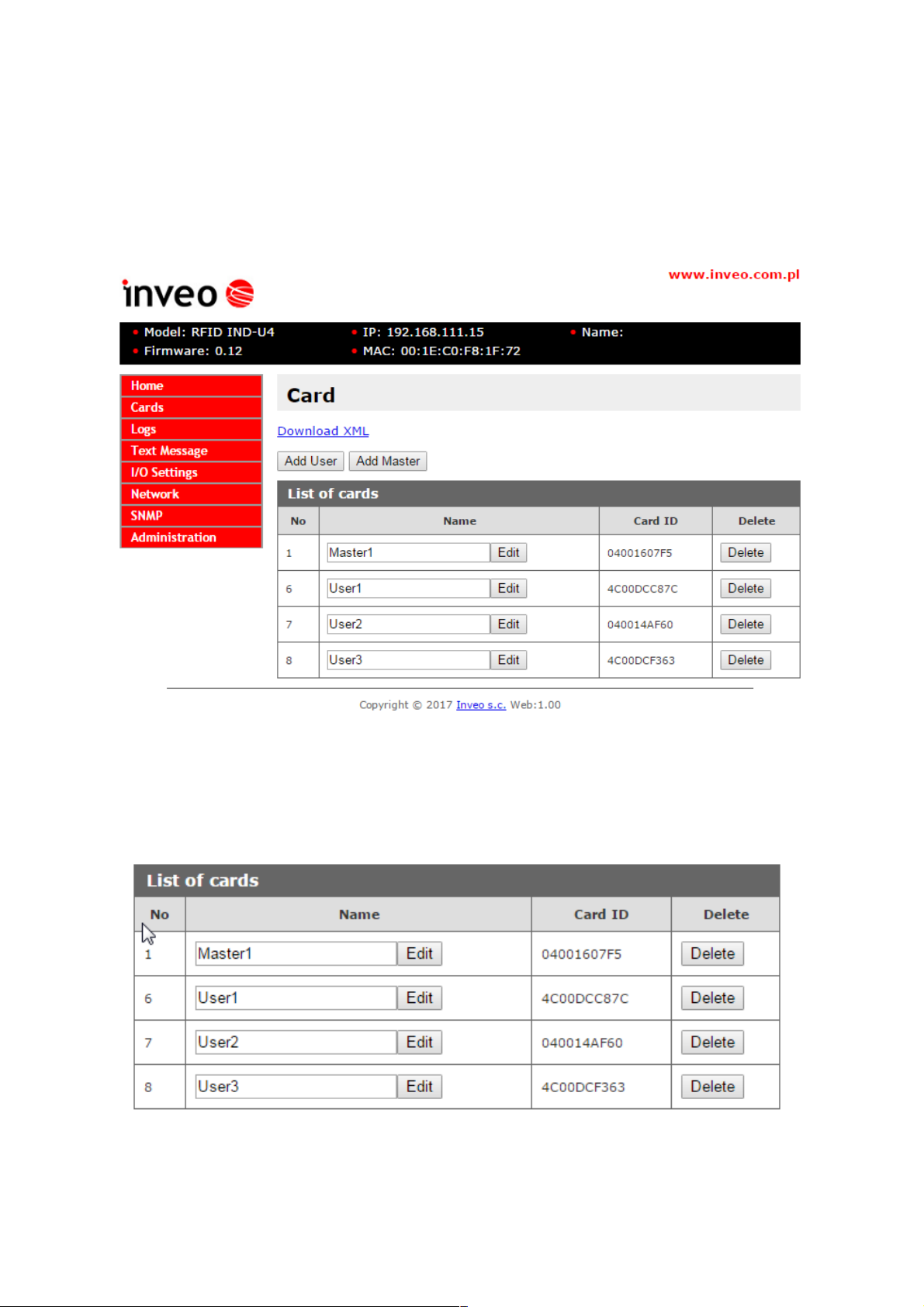
6.3 CARD MANAGEMENT - CARDS TAB. ADD AND REMO E CARDS FROM THE BROWSER..................................................10
6.4 LOGS...............................................................................................................................................................11
6.5 TEXT MESSAGE.................................................................................................................................................13
6.6 REACTIONS TO THE E ENTS - I / O SETTINGS.........................................................................................................14
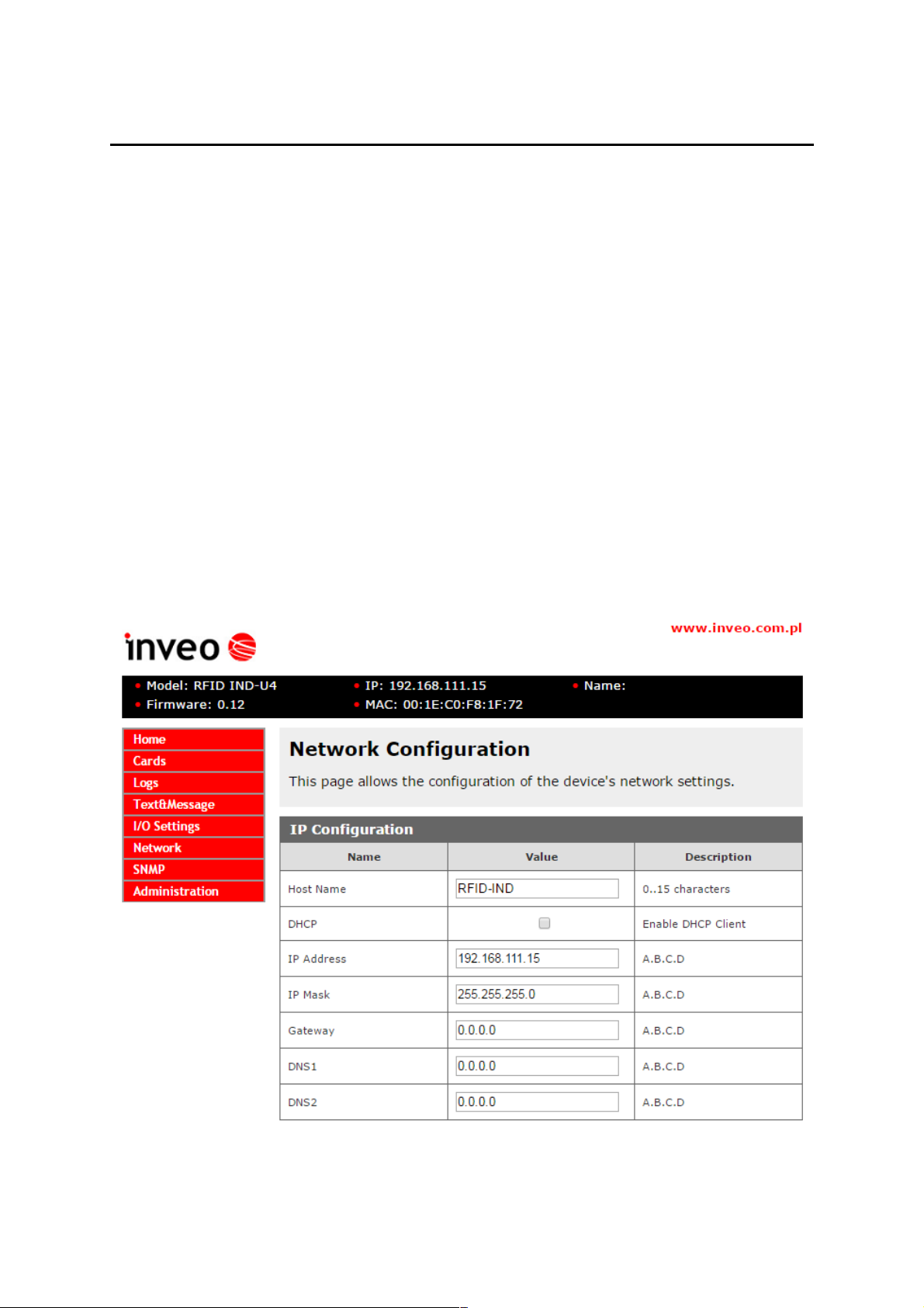
6.7 NETWORK CONFIGURATION..................................................................................................................................16
6.8 SNMP............................................................................................................................................................18
6.9 COMMUNICATION PROTOCOLS AND ADMINISTRATION.................................................................................................19
7 COMMUNICATION WITH MODULE..........................................................................................................21
7.1 THE MODBUS ADDRESSES..............................................................................................................................21
7.2 READING THE MODULE STATUS IA HTTP GET....................................................................................................22
7.3 HTTP GET CONTROL......................................................................................................................................23
7.4 CONTROL O ER HTTP IN CLIENT MODE...............................................................................................................25
7.5 INTEGRATION WITH OWN SOFTWARE......................................................................................................................26
7.6 COMMUNICATION WITH A MODULE FROM AN EXTERNAL NETWORK..............................................................................27
8 CONNECTOR DESCRIPTION.......................................................................................................................28
DHCP...................................................................................................................................................................2
10 RESTORE FACTORY SETTINGS................................................................................................................30
11 SOFTWARE UPDATE.....................................................................................................................................30
NOTES..................................................................................................................................................................31
User manual RFID IND-U4, RFID IND-U2 Pa e 3 from 31

1 Preliminary informations
Before starting work with the evice, rea The User manual an follow the
instructions containe therein!
Describtion of visual symboles used in this user manual:
This symbol is responsible for reviewin the appropriate place in the
user instructions, warnin s and important information. Failure to
follow warnin s could cause injury or dama e to the module
Important informations and uidelines
Followin this uidelines makes the use of the module easier.
Attention: The appearance of the screen shots shown in this manual may differ sli htly
from the actual work with the module. The differences may relate to the size and font
type and size of symbols. There are no differences in the content of the information.
User manual RFID IND-U4, RFID IND-U2 Pa e 4 from 31

2 Purpose of the evice
RFID IND U2 and U4 are readers used to read RFID Unique format ta s and inte ration
with other systems via MODBUS TCP, HTTP client / server, SNMP. The reader can also
work as a standalone device.
3 Warranty an liability of the manufacturer
The manufacturer provides a 2-year warranty on the module. The manufacturer also
provides post-warranty service for 10 years from the date of the introducing the module on
the market. The warranty covers all defects in material and workmanship
The manufacturer undertakes to comply with the contract of guarantee, if the following
conditions are met::
all repairs, alterations, extensions and device cali rations are performed y the
manufacturer or authorized service,
supply network installation meets applica le standards in this regard,
the device is operated in accordance with the recommendations outlined in this manual
the device is used as intended..
The manufacturer assumes no responsibility for consequences resultin from improper
installation, improper use of the module, not followin this manual and the repairs of the
module by individuals without permission.
This evice oesn’t contain serviceable parts.
User manual RFID IND-U4, RFID IND-U2 Pa e 5 from 31

4 Safety gui elines
The module has been constructed usin modern electronic components, accordin to the
latest trends in the lobal electronics. In particular, much emphasis was placed on
ensurin optimum safety and reliability of control.
The device has a housin with a hi h-quality plastic.
4.1 Power supply
RFID IND-U4 and RFID IND-U2 are suitable for power supply 10-24VDC or POE IEEE
802.3af (selected durin production).
4.2 Storage, work conditions.
The reader is equipped with a sealed IP65 enclosure which means:
•total resistance to forei n objects
•resistance to water jet directed directly to the device
•stora e and operation at temperatures from -25 ° C to + 60 ° C,
4.3 Installation and use of the module
The mo ule shoul be use following the gui elines shown in next part of
the user manual.
4.4 Utilisation of the module
When it becomes necessary to liquidate the device (e. ., after the time of use), please
contact the manufacturer or its representative, who are obli ed to respond appropriately,
i.e., collectin the module from the user. You can also ask the companies involved in
utilization and / or liquidation of electrical or computer equipment. Under no
circumstances should you place the device alon with other arba e
User manual RFID IND-U4, RFID IND-U2 Pa e 6 from 31

5 Construction of the mo ule
.1 General features
General view of the RFID IND-U4 and RFID IND-U2 is shown below.
Communication with the module is carried out by the LAN or RS485.
User can choose from the followin options to access the code read from the RFID ta :
–throu h built-in web server, usin a standard web browser (preferred browsers
are Mozilla Firefox, OPERA, CHROME)
–HTTP server mode
–HTTP client mode
–MODBUS TCP
–MODBUS RTU (RS485)
–SNMP
The module, dependin on the version, is equipped with an LCD display (IND-U4) or LEDs
(IND-U2) that si nal the power and current state of the device.
5.2 Technical ata
Supply volta e: 10-24VDC or PoE 802.3af
Power consumption: max 2,5W ( ~200mA@12V)
Power supply: terminal block, POE 802.3af or POE passive
Communication: Lan and RS485
Maximum relay current:1A@30VDC
Read ta s standard: UNIQUE,
Ta readin distance: up to 8cm
Dimensions: hei ht: 50.0 mm, width: 100.0 mm, len th: 100.0 mm
User manual RFID IND-U4, RFID IND-U2 Pa e 7 from 31
General view of the RFID IND-U4
mo ule
General view of the RFID IND-U2
mo ule

6 Configuration of the evice
If usin the controller for the first time it is needed to confi ure the controller as shown
below
6.1 Changing the PC settings for controller configuration.
After connectin the controller to the network there is a need to chan e the PC settin .
In order to do that navi ate to: Start->Control Panel->Network connections.
Then ri ht click on the current network connection and click „Properties”.
Choose the „Internet Protocol (TCP/IP)”, press „Properties”. Tick the box „Use the
followin IP address” and type as followin :
IP address: 192.168.111.1
Subnet Mask: 255.255.255.0
The rest of the settin can be left blank.
Press OK to accept the chan es
Start the web browser and enter the followin address into address bar: 192.168.111.15.
(Default user an passwor : a min/a min00)
Then select the menu "NETWORK"
User manual RFID IND-U4, RFID IND-U2 Pa e 8 from 31
Configure of the network connection

To chan e the network settin s of the module, use the followin fields:
Host Name – NETBIOS name,
DHCP – checkin this box forces use the address assi ned by the DHCP server
IP Address – the IP address of the module (at this address, the module will be visible
on the network),
IP Mask – IP subnet mask,
Gateway – network ateway,
DNS1 – DNS servers addresses,
DNS2 – DNS servers addresses,
After makin chan es, click Save.
6.2 The device status - HOME tab
After selectin the HOME are displayed:
Status table:
Input 1 – the current input status number 1 (binary input)
Input 2 – the current input status number 2 (binary input)
Relay – the current status of the relay output
Last rea ID - last read ta in the HEX format
Number of rea ID - the number of ta s read since the device reset
Warning!
Displayed in the position Last read ID:8500c2b4a8 (LOCK!) marker means that the
readin of next ta s is blocked until cleared with the releaseid commands.
User manual RFID IND-U4, RFID IND-U2 Pa e 9 from 31

6.3 Card Management - CARDS tab. Add and remove cards from the
browser.
In the Card tab is the ability to manually assi n a USER cards and a MASTER cards that
the reader will reco nize.
To add a new user card, on the Cards tab, click the A User button, and then brin the
card closer to the reader. The assi nment of the card will be si nalised by the appropriate
beep. In the same way master cards can be added, by clickin the A Master button.
After addin the card to the reader correctly, their numbers will appear in the List of
car s
The reader automatically adds a User name that can be chan ed by editin the Name
field. Removin the card from the memory is done by clickin the Delete
User manual RFID IND-U4, RFID IND-U2 Pa e 10 from 31

All cards in the reader can be retrieved by referencin the resource car List.xml
Sample screenshot:
6.4 Logs
Inthe Logs menu, the reader writes the Id of all applied rfid ta s.
To save all ta usa e events in the reader memory in the Administration Lo in → →
Lo mode and select the appropriate lo in mode.
Log mo e: Disable - lo in disabled;
Log mo e: Base ID-Table – the reader in the Lo table will display the name defined
in the Card menu;
Log mo e: Car ID number – the reader in the Lo table will display the card number
in the HEX format.
User manual RFID IND-U4, RFID IND-U2 Pa e 11 from 31

Sample lo s in Based ID-Table mode:
Sample lo s in Card ID Number mode:
The reader has a built-in real time clock. Clickin on the Up ate time button will
synchronize the internal clock with the current time set in the computer.
Clickin the Remove logs button removes all lo s from the reader memory.
User manual RFID IND-U4, RFID IND-U2 Pa e 12 from 31

The user can download all lo s that are in the readers memory by reference to the
resource lo List.xml
If usin Base ID-Table mode - 229000 lo s can be saved in the reader memory. By
usin Car ID Number mode 152000 lo s can be saved.
6. Text Message
In the Text Messa e menu, set the text showed on the display durin various actions,
such as applyin an active card, applyin an inactive card, waitin time.
User manual RFID IND-U4, RFID IND-U2 Pa e 13 from 31

In the Time table you can set the lan ua e in which the time in the first line of the
display will be displayed:
6.6 Reactions to the events - I / O Settings
In the Input 1 table, activatin the Door unlock option allows the output relay (bolt) to
be automatically activated by activatin Input 1.
In the Output Relay table can be set the operatin mode of the bolt control relay.
O.n. Name Description
1 Mode Disable - Turn off relay control.
1-Pulse - After the activation of the output, the relay is switched on
for a certain time (e the control of the bolt)
Toggle - After activatin the output, the state chan es to the opposite
2 Time-on Relay on time in 1-Pulse mode, iven in 0.1s (value 20 is 2 seconds)
3 Action The action that causes the activation of the output.
None (control by protocol) - The control is carried out throu h the
protocol HTTP, SMNP, MODBUS.
Every Car - Activation of output with each RFID ta application.
Recogniza Car - Activation of the output after applyin the active
ta (stored in the reader's memory)
User manual RFID IND-U4, RFID IND-U2 Pa e 14 from 31

In the Events table, can be pro rammed the reaction of the reader when after applyin
the rfid ta .
O.n. Name Description
1 Sound
Action
An action that tri ers a beep.
None (control by protocol) - The audio enerator is controlled by
the protocol HTTP, SMNP, MODBUS.
Every Car - Activation of the sound enerator occurs every time the
rfid ta is applied.
Recognize Car - Activation of the sound enerator takes place after
applyin the active ta (stored in the reader's memory
2 LED/LCD
Backli ht
Action
An action that activates the LCD display or LEDs.
None (control by protocol) - The control is carried out throu h the
protocol HTTP, SMNP, MODBUS.
Every Car - Si nalin each time the rfid ta is applied
Recognize Car - Si nalin after applyin the active ta (stored in
the reader's memory)
InU4 model back li htin of the display can be controlled.
When the value is set on 255 the displayed li hts constantly.
When the value is set on 0 the back li ht is off.
When the value is set, for example on 5 the display will li ht for 5 seconds after
approachin the ta .
User manual RFID IND-U4, RFID IND-U2 Pa e 15 from 31

6.7 Network configuration
The reader is equipped in internal real time clock (RTC) wich be synchronized with time
server by SNTP protocol. Confi uration of the settin s can be done in the tab
Administration SNTP→
To plu in the service of synchronization in the field Server type IP address of any time
server. Typin 0.0.0.0 causes disablin the synchronization.
User manual RFID IND-U4, RFID IND-U2 Pa e 16 from 31

If Enable HTTP Client mode is on there is a need to set the address to send the data on.
It is possible in the table Network HTTP Client Confi uration →
O.n. Name Description
1 Server The IP address of the server on which the reader will send data
2 Port The port on which the server listens
3 Resource The resource referenced by the reader, for example: /somefile.php
4 Poll time The period of sendin data to the server
Poll time=0 – data is only sent when the rfid ta is applied
Poll time>0 – data is sent cyclically
e .: Poll time=50 – data will be sent every 5 seconds
User manual RFID IND-U4, RFID IND-U2 Pa e 17 from 31

6.8 SNMP
The module is equipped with an SNMP v2c server. Enablin the feature is possible
in the tab A ministration -> Services -> Enable SNMP .
SNMP allows to download the inputs state, set the output state and download read out
ta number. MIB file describin the structure is available for download in the tab SNMP
-> Downloa MIB file.
User manual RFID IND-U4, RFID IND-U2 Pa e 18 from 31

6.9 Communication protocols and administration
The Administration menu allows to confi ure services to be active and chan e access
password.
Mo ule name
Each reader can be iven an unique name used to identify.
Passwor
To chan e the password in the field Current Passwor actual password. In the fields
New Password and Re-type Password type new password and confirm with Save
Config button.
To disable the password request leave the field New Passwor empty.
Service setting
The device allows to select which services are to be available. Selectin the check box
next to the service name activates the selected service.
Autonomic – set the reader to standalone mode
Enable MODBUS TCP– activation of MODBUS TCP service
Enable MODBUS RTU– activation of MODBUS RTU service
Enable SNMP – enablin SNMP protocol
Enable HTTP GET – selectin module mode as HTTP server
Enable HTTP Client – selectin module mode as HTTP client
Enable TFTP Bootloa er – turn on the bootloader
User manual RFID IND-U4, RFID IND-U2 Pa e 19 from 31

Warning:
TFTP Bootloader should be isable durin normal operation. It should only be activate
before the software update.
RS485 port setting for MODBUS RTU communication.
O.n. Name Description
1 PDU Modbus address of the device.
2 Baudrate Data transfer rate.
Available speeds: 1200, 2400, 4800, 9600, 19200, 34800, 57600,
115200
3 Parity Parity settin s.
Available options:
None, None and 2 Stop, Even, Odd, Mark, Space
User manual RFID IND-U4, RFID IND-U2 Pa e 20 from 31
This manual suits for next models
1
Table of contents
Other inveo Control Unit manuals
Popular Control Unit manuals by other brands

Honeywell
Honeywell Resideo ADEMCO 4101SN V-Plex Installation and setup guide

Agilent Technologies
Agilent Technologies E8257DS02 user guide

Siemens
Siemens FDCI221 Installation

LOVATO ELECTRIC
LOVATO ELECTRIC VLBXSM installation manual

Allen-Bradley
Allen-Bradley 1756 ControlLogix Reference manual

MEIG
MEIG SRM825N-NA user manual