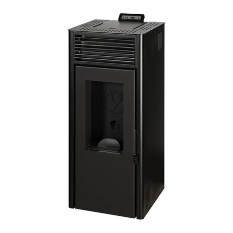
Invicta TIPI 6153 44 User manual

TIPI
STOVE
reference 6153 44
NB le 15/02/2011 Page 1sur 9
TIPI
STOVE
Reference 6153 44

TIPI
STOVE
reference 6153 44
NB le 15/02/2011 Page 2sur 9
Special instructions for installation and use of this model
Carefully read these special instructions for this model along with the general instructions provided with the appliance
Characteristics in compliance with EN 13240:
1585
4
0
0
Ø 600
Ø 754
Ø 200
5
8
5
Rated power 10 kW
Output power 78 %
CO emission % 0.05 %
Flue gas temperature T° 293 °C
Operating mode Continuous and Intermittent
Recommended fuel Wood (Horn) / logs 25 cm
Smoke removal rate 7.5 g/s
The appliance must not be directly set down on a floor made from combustible materials or one
which will deteriorate under the effect of heat. If such is the case, place the appliance on a tiled
hearth or reflective metal plate to protect the floor from high temperatures.
Minimum distance to keep between the stove and nearby combustible materials:
- Back 60 cm
- Lateral 60 cm
If the adjoining sides are in non-combustible material and do not damage under heat effect
(temperature of the wall can reach 200°C), those dimensions can be reduced to 15 cm.
Appliance weight 143 kg
Connection to the flue via the outlet pipe located
on the top of the appliance Diameter : 200 mm
Logs maximal length
40 cm
(vertical loading 50 cm)
Overall size h 1585 mm Ø 754 mm
Door dimensions h 585 mm lg 473 mm
Fire view h 461 mm lg 378.5 mm
Serial plate Riveted on the ashtray side

TIPI
STOVE
reference 6153 44
NB le 15/02/2011 Page 3sur 9
INSTRUCTIONS FOR INSTALLATION
To limit the warming of the walls that forming the chimney surround, at 65K (K= Celsius above ambient temperature), and obtain a
smooth functioning, it’s necessary to respect the disposition principal of below schemes.
If the adjoining sides are in non-combustible material and do not damage under heat effect (temperature of the wall can reach 200°C), those
dimensions can be reduced to 15 cm.
USING ADVICES WITH CLOSED DOORS
:
•Precautions when commissioning.
Put the deflector in place (see instructions and scheme page 7)
-During the first using, a paint smell will get out of the appliance : ventilate the room to limit this inconvenience or make a
first use outside the house.
Ignition :
Place crumpled paper on the grid and dry splint (small branches well dry or fine-chopped wood). Set fire to the paper, close the door,
and open entirely the air control. When it’s well flamed, you can load your appliance. It’s recommended, during first hours, to do a moderate fire,
to let a normal dilation of the whole appliance
Functioning intermittent and continuous :
The ‘Intermittent’ functioning need a loading every 45 minutes with small quantity of wood. It’s necessary to privilege this functioning mode
particularly performant and eco-aware.
The appliance can also assure a ‘continous’ functioning when intermittence confines cannot be respected, or when a reduced output is wanted.
In that case, the full load can be obtained during 3 hours, and, at moderate pace and low power, 10 hours is possible.
Nominal heat output
: in ’Intermittent’, it’s obtained with a 12 Pa draught, with a 3 kgs loading of wood, 2 half-logs of hard wood, renewed
every 45 min, with a bed of glowing embers (3cm), with ‘normal rate’ regulating (figure 1 page 7). In ‘’Continuous’’ loading is led to 6-8 kg in
3 logs, renewed every 3 hours.
A lower activity can happen due to unfavourable evolution of combustion, an inappropriate geometry of logs, too hard wood using or too wet.
Those slowing down phenomenons, which are not exceptional or totally predictable, resulting into a decrease of the blanket of flames (the
combustible forms a vault and is not in contact with braise anymore), the progressive decrease of the braise reserve and the hearth cooling.
They are accompanied by a power drop, and performance decrease.
To avoid this : carefully open the door of the hearth/stove, reorganize the load on the ember bed, picking and move the combustible with a
poker, watching out for braises falling over the hearth, then close again the door. The activity regains immediately after closing the door.
•Slow combustion of 10 hours :
it’s obtained under a 6Pa draught with a 6-8 kgs load, constituted of 1 or 2 hard logs non chopped,
favouring high diameter (more than 16 cm, 6.3 “), and closing completely the pace register. Complete beforehand a reduced rate of flow by
closing the air register, to then load on a barely glowing ember bed / braises.
600
mm
600
mm
Rear
wall
Lateral
wall
ST
OVE INSTALLATION TOP VIEW

TIPI
STOVE
reference 6153 44
NB le 15/02/2011 Page 4sur 9
•Deashing :
To evacuate ashes :
Wait for the complete cooling of the appliance.
Collect, then, make the ashes fall out through the grids with a poker.
Lastly, extract the ashpan, and empty it in a metal container reserved to this use only, that contains no flammable material
and/or trashes, and keep it outside your house
Then, put back the ashpan and the grids
Proceed to this operation before the ashpan get full.
•Regulating system / adjustments :
Always use the cold hand tool supplied with the appliance to manipulate regulating system that can be super hot.
Pace damper (see fig.1 page 7, located at the bottom of the faceplate): this damper is used to change the appliance from
“normal burning” to “slow burning” (closed position) and back.
Ignition register (see fig.1 page 7)
This action , beyond normal pace position, permits to obtain an air supplement for firing.
This position is reserved to lighting and regaining operations, and must not last more than 30min, to avoid appliance and environment
damages. The appliance must stand under surveillance during this position using.
Secondary air inlet (see fig.2 page 7) :
This register must stand open to obtain a performant functioning and a clean combustion
Closing this register is not justified unless draughts are higher than the recommended ones (see above). In this instance, this register can be
partially closed to get a satisfying functioning. Once this adjustment is done, do not act on this secondary air register anymore, and use
exclusively the primary air regulating register, to make the appliance power vary.
USING ADVICES WITH ‘OPENED DOORS‘:
•This functioning is possible only after ignition and load with closed doors
•With normal draft and well dry wood, re-load on a 3 cm live coat bed
•Do not load more than what is specified about ‘nominal heat in intermittent’ (see above)
•Keep under survey when functioning with doors opened
Note :
When functioning with opened doors, the appliance becomes an element of a group including the joining duct, the pipe, the
chimney stack, and the ventilation of the house.
The absence of backdraft when functioning ‘doors opened’ is the result of a frail balance between the drawing in capacity of the
duct, the right fresh air alimentation, the respect of use instructions, and, at the installation level, parameters proper to the area of
use( chimney height, prevailing winds and so on…)
Balance that can be guaranteed only by the craftman/installer.

TIPI
STOVE
reference 6153 44
NB le 15/02/2011 Page 5sur 9
1
2
3
5
6
7
8
9
10
2
3
4
4
5
5
5
6
5
6
11
12
14
15
17
16
18
19
20
21
13
23
22
24
25
27
28
30
3
26
28
29
31
32
33
34
35
36
37
38
38
39
40
41
42
43
44
45
45
46
46
47
48
49
50
51
51
52
52
52
52
53
53
54
54
55
55
56
56
57
58
59
60
60
61
61
62
63
64
65
66

TIPI
STOVE
reference 6153 44
NB le 15/02/2011 Page 6sur 9
Repère Nbr Désignation Référence
1 1 Fond
FB
610381
2 2 Cale oblique de 8
AV
4240080
3 2 Rondelle de 6 large
AV
4110060
4 2 Vis tête hexagonale de 6x30
AV
8406300
5 20 Rondelle de 8 large
AV
4110080
6 10 Ecrou de 8
AV
7100080
7 1 Avaloir
FB
610390
8 1 Dessus
FB
610384
9 3 Tirant
AS
610136A
10 1 Cendrier
AT
610142C
11 1 Plaque signalétique
PS
615344
12 2 Rivet de 3x8
AV
5203080
13 1 Taque
FB
610392
14 3 Vis tête bombée empreinte hexagonale creuse de 6x20
AV
8686200
15 2 Vis tête cylindrique empreinte hexagonale creuse de 6x20
AV
8666206
16 1 Registre de réglage d’arrivée d’air secondaire
AT
610144A
17 1 Déflecteur
FB
610395
18 1 Bride
AT
610147B
19 1 Panneau de vermiculite gauche
AI
703111A
20 1 Coté gauche
FB
610383
21 1 Joint thermocorde Ø12, longueur 1.016 mètre
AI
3030012
22 1 Panneau de vermiculite droit
AI
703110A
23 1 Coté droit
FB
610382
24 4 Vis tête hexagonale de 8x40
AV
8408400
25 1 Socle
FB
610380
26 1 Joint thermocorde Ø5, longueur 0.631 mètre
AI
303005
27 1 Support de grille foyère gauche
FB
610389
28 2 Grille foyère
FB
610391
29 1 Ecrou de 8 frein
KAV
7010080
30 1 Support de grille foyère droit
FB
610388
31 1 Tôle d’appui
AT
610351B
32 1 Vis tête fraisée empreinte hexagonale creuse de 6x16 inox
AV
8636166
33 1 Rondelle de 6
AV
4100060
34 1 Bouton de registre
AS
750120A
35 1 Registre de réglage d’arrivée d’air primaire
AT
610143B
36 1 Vis de registre
AS
750123C
37 1 Ressort registre
AS
750125A
38 6 Vis tête hexagonale de 8x25
AV
8408250
39 3 Pied
FB
610393
40 2 Ecrou de 6
AV
7100060
41 1 Guide d’air
FB
610394
42 1 Joint plat, longueur 0.646 mètre
KAI
010080
43 1 Façade
FB
610385
44 1 Joint thermocorde Ø12, longueur 1.713 mètre
AI
303212
45 2 Equerre support excentrique
AT
610146A
46 4 Vis tête fraisée empreinte hexagonale creuse de 6x10
AV
8636100
47 2 Vis tête fraisée empreinte hexagonale creuse de 6x35
AV
8636350
48 2 Entretoise de roulement excentrique
AS
610306A
49 2 Ecrou bas de 6
AV
7130060
50 2 Axe excentrique
AS
610307A
51 2 Vitre
AX
615344A
52 6 Vis tête cylindrique empreinte pozy de 4x6
AV
8644062
53 6 Attache de vitre
AS
700262
54 2 Bague de rotation
AS
610137B
55 2 Axe de rotation
AS
610138A
56 2 Joint thermocorde Ø5 (vitrage), longueur 1.166 mètre
AI
303005
57 1 Porte gauche
FB
610387
58 1 Porte droite
FB
610386
59 1 Joint thermocorde Ø5, longueur 0.523 mètre
AI
303005
60 4 Vis tête bombée empreinte hexagonale creuse de 4x10
AV
8684100
61 2 Bride de tringlerie
AT
610147B
62 1 Tringle
AT
610145B
63 1 Poignée
AD
800000A
64 1 Main froide
AS
800255
65 2 Vis tête fraisée empreinte hexagonale creuse de 5x10
AV
8635100
66 1 Chenet
FB
610396

TIPI
STOVE
reference 6153 44
NB le 15/02/2011 Page 7sur 9
FIGURE 1
Position fermée
du registre
d’arrivée d’air
Figure 1 : Closed position of the air control
Position
d’allure
normale
Normal pace position
Position d’allumage du registre
arrivée d’air (entièrement ouvert) :
à n’utiliser que pour lesphases
d’allumage et de reprise en
gardant l’appareil soussurveillance!
Air control position for ignition (wide open) : only use for ignition and regain phases, keeping the appliance under survey
FIGURE 2
Secondary air inlet
REGISTRED’ARRIVEE
D’AIRSECONDAIRE

TIPI
STOVE
reference 6153 44
NB le 15/02/2011 Page 8sur 9
DEFLECTOR ASSEMBLY
1
23
BOSSAGE
- Enlever le carton de calage
- Couper le lien qui maintien le déflecteur aux grilles
- Monter le déflecteur à la verticale dansl’appareil
- Poser lesbossagesdu déflecteur sur la taque
- Laisser reposer sur le guide d’air l’avant du déflecteur
2
3
1

TIPI
STOVE
reference 6153 44
NB le 15/02/2011 Page 9sur 9
Take off the chocking cardboard
Cut the link that maintains the deflector to the grids
1- Put up vertically the deflector in the appliance
2- Install the humps of the deflector on the fireback
3- Let the front of the deflector rest on the air guide
Table of contents
Other Invicta Stove manuals
Popular Stove manuals by other brands

St. Croix
St. Croix Freestanding stove installation manual

Osburn
Osburn Romance 28 owner's manual

Diamond
Diamond G2 Series operating instructions

Charnwood
Charnwood ARC 5 Operating & installation instructions

Lincar
Lincar Luna 515N Using instructions and maintenance

AMI
AMI 4E Operating and installation instruction

Charnwood
Charnwood COVE Series Operating & installation instructions

FRANCO BELGE
FRANCO BELGE Belfort 134 04 11 Technical manual

Lopi
Lopi Liberty owner's manual

Jydepejsen
Jydepejsen Omega user manual

Parmco
Parmco AR600 Installation and operating instructions

Quadra-Fire
Quadra-Fire OUTFITTER-II installation manual