InWin IW-RJ460-05 User manual

IW-RJ460-05
User’s Manual

TableofContents
PREFACE.......................................................................................................................................1
SAFETYINFORMATION.................................................................................................................1
CAUTION......................................................................................................................................2
SPECIFICATIONS............................................................................................................................3
1ProductIntroduction.............................................................................................................4
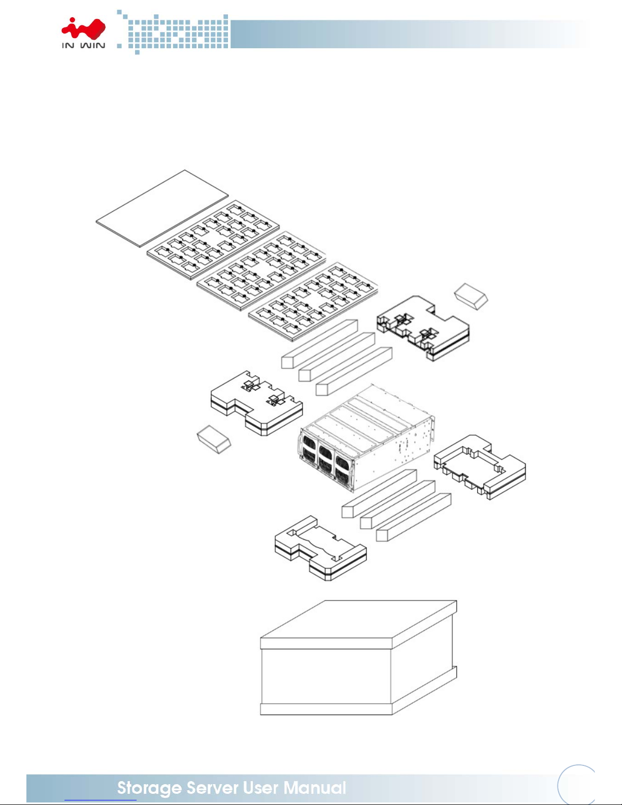
1.1BoxContents............................................................................................................................4
1.2GeneralInformation.................................................................................................................5
1.2.1FrontPanelControlsandIndicators..........................................................................................................6
1.2.2RearPanelConfiguration...........................................................................................................................7
1.2.3ExpanderConfiguration.............................................................................................................................8
2HardwareInstallation...........................................................................................................9
2.1RemovingandInstallingaHardDrive........................................................................................9
2.1.1InstallingaHardDrive................................................................................................................................9
2.1.2RemovingaHardDrive............................................................................................................................11
2.2RemovingandInstallingtheFanModule.................................................................................11
2.2.1RemovingtheFanModule.......................................................................................................................11
2.2.2InstallingtheFanModule........................................................................................................................12
2.3RemovingandInstallingthePSUModule................................................................................13
2.3.1RemovingthePSUModule......................................................................................................................13
2.3.2InstallingthePSU+FANModule...............................................................................................................13
2.4RemovingandInstallingtheExpanderModule.......................................................................14
2.4.1RemovingtheExpanderModule.............................................................................................................14
2.4.2InstallingtheExpanderModule...............................................................................................................14
2.5RailInstallation.......................................................................................................................15
2.5.1TheTypeofRailKit...................................................................................................................................15
2.5.2FixedRailBlades.......................................................................................................................................15
2.5.2.1InstallingtheSupportBartotheRack................................................................................................15
2.5.2.2InserttheChassistotheRack.............................................................................................................15
3ExpanderBoardIntroduction..............................................................................................17
4EthernetManagementCardIntroduction...........................................................................18
5UserInterfaceIntroduction.................................................................................................19

5.1Overview................................................................................................................................19
5.2KeyFeatures...........................................................................................................................19
5.3SoftwareManagement...........................................................................................................20
5.3.1SystemManagementStructure...............................................................................................................20
5.3.2SerialPortManagement..........................................................................................................................21
5.3.3NetworkManagement.............................................................................................................................24
5.3.4VersionInformation.................................................................................................................................30
5.3.5SystemStatus...........................................................................................................................................32
5.3.6NetworkSettings......................................................................................................................................33
5.3.7DiskInformation.......................................................................................................................................34
5.3.8FirmwareUpgrade....................................................................................................................................35
5.3.9WebConsole.............................................................................................................................................41
5.4AppendixA.............................................................................................................................42
5.5AppendixB.............................................................................................................................42
6CompatibilityLists..............................................................................................................44
7TechnicalSupport................................................................................................................44

1
PREFACE
ThankyouforchoosingtheInWinIW‐RJ460‐05.Thismanualiswrittenforsystemtechnicianswho
areresponsibleforinstallation,troubleshooting,managingandrepairingthisserverchassis.This
documentprovidestheoverviewofallthefeaturesofthechassis,alistofaccessoriesorother
componentsyoumayneedtofinishtheinstallation,troubleshootingmethodsandinstructionson
addingandremovingcomponentsontheInWinIW‐RJ460‐05.Forthelatestversionofthismanual,
youmayvisitInWin’sserverwebsitetodownloadthelatestupdatedversion.
SAFETYINFORMATION
ToensureasafeandsmoothoperationofyourInWinIW‐RJ460‐05,itisessentialthatyouchoose
anappropriatelocationforthesystem,provideanappropriateoperatingenvironmentandsupply
anadequateamountpowerforallcomponentsofthesystem.Asyouplanforinstallation,follow
theguidelinesbelowtoensurethatthesystemanditsenvironmentaresafelyandappropriately
positionedforefficientoperationandservice.Yoursystemshouldbeinstalledandservicedonlyby
aqualifiedtechnician.
Environmentselection:Thesystemisdesignedtooperateinatypicalofficeenvironment:
Thelocationshouldbeclean,dryandfreeofairborneparticles.
Itshouldbesituatedinawell‐ventilatedroom,andawayfromsourcesofheatincludingdirect
sunlightandradiators.
Itshouldbekeptawayfromsourcesofvibrationorphysicalshock.
Thespaceshouldbeaccommodatedwithaproperlygroundedwalloutlet,andwithsufficient
spacetoaccessthepowersupplycords.
Theoperatingenvironmenttemperatureshouldbearound0°Cto40°C(32°Fto104°F).
Heedsafetyinstructions:BeforeworkingwithInWinIPC/Storageserverproducts,westrongly
recommendyouusethisguideasareferenceandfollowthesafetyinstructions.Theinstructionsin
thismanualwillhelpyouensureandmaintaincompliancewithexistingproductcertificationsand
approvals.Followthedescribed,regulatedcomponentsmentionedinthismanual.Useofnon‐UL
listingproductsorotherregulatorsmaynotcomplywithproductregulationsintheregion(s)in
whichtheproductissold.
Systempoweron/off:ThepowerbuttonDOESNOTtotallyturnoffthesystemACpower.To
removethepowerofthesystem,youmustunplugtheAC
powercordfromtheoutletorthesystem’spowersupplyunits.Makesurethepowercordis
unpluggedbeforeyouopenthechassisoradd/removeanycomponents.
Hazardousconditions,devicesandcables:Hazardouselectricalconditionscanbepresenton/in
powersupplyunitsandtheircables.Disconnectthepowercordandanyotherdeviceattachedto
theserverbeforeopeningthecase.Failingtofollowsafetyprocedureswillincreasetheriskof
personalinjuryorequipmentdamage.

2
Electrostaticdischarge(ESD)andESDprotection:Inmostcases,ESDmaydamagediskdrives,
electronicboardsandotherparts.WerecommendthatyouconductinstallationonlyatanESD
freespace.Ifnotpossible,performESDprotectionprotocolbywearinganti‐staticwriststraps
attachedtothegroundonanyunpaintedmetalsurfaceonyourserverduringoperation.
Installingorremovingjumpers:Ajumperisashortlengthconductorusedtoclose,openorbypass
partofanelectroniccircuit.JumpersonInWinbackplaneshaveasmalltabontopthatyoucan
pickupwithyourfingertips.Gripthejumpercarefully,andplugthejumpertocoverthejumper
pinsonthebackplane.Onceyouneedtoremovethejumper,gripthejumperandcarefullypull
withoutsqueezing.
CAUTION
Toavoiddamageandmaintainyoursafety,pleasereadthefollowingtermslistedbelow:
1. Donotpopulateharddrivesandturnonthepoweruntilthesystemhas
stabilized.
Makesureharddrivesandothercomponentsareproperlyconnectedbefore
turningonthesystem.
2. Tightenorloosenallscrewswithascrewdriver.
3. Applythecorrectscrewspackedintheaccessorybox.
4. Foryoursafety,pleasehaveatleasttwopeopleliftandplacetheunitinits
designatedarea.
5. Beforemountingtheunittothecabinet,makesuretherailisinstalledcorrectly.
6. Wheninstallingandremovinganymoduleorpart,pleaseusethehandles.

3
SPECIFICATIONS
ModelNameIW-RJ460-05
StandardEIA‐RS310D
Dimensions(DxWxH)
w/oFrontDoor812.8x482.6x176mm(32"x19"x7")
StorageExternal:Hot‐swap3.5"x60(SAS12Gb/s,20baysperdrawer)
PowerSupply
Supports
▪FormFactor:PlatinumCRPSredundantwithPDBcable
management
▪Watt:1200W
CoolingFan97x33mmPWMblowerx6
12GExpanderModule1or2
Host/ExpansionPort8xMiniSASHD(SFF‐8644)foreach12Gexpandermodule
ManagementSmartfan,thermalmonitor,HDDmonitor,voltagemonitor,alarm
warning
SESSupportsSES‐2(SCSIEnclosureService)
MaintenanceSupportsmanagementbyEthernet(Optional)andRS‐232
HDDPowerManagementHDDsequentialpoweron
Temperature0ºCto35ºC
MaterialMaterial:SGCC
Thickness:1.0mm
RailKitFixedrailblade
*Theactualproductissubjecttochangewithoutpriornotice.InWinDevelopmentInc.reservesthe
righttomakeanyfinalmodifications.

4
1ProductIntroduction
1.1 BoxContents

5
1.2 GeneralInformation
IW‐RJ460‐05JBODenclosureisahighdensity4Urackmountstoragechassiswith60tool‐less
bays,dualexpandermodules,sixblowerfanmodules,anddual1200WPlatinum‐levelCRPS
powersupplymodulesfor1+1redundancy.
OpposingHDDbaysdesignedtooffsettorquesandminimizesrotationalvibrationaggregation
andsupportstheGUIviaanEthernetboard(optional).

6
1.2.1 FrontPanelControlsandIndicators
ThefrontpanelincludescontrolbuttonsandLEDindicators.
No.NameColorStatus Description
1SystemStatusLEDFollowthetable
below
2DriveStatusLED
3DriveModuleLatch‐‐OpenstheHDDdrawer
DriveStatusLED:
(Solid)DriveOnline
(Blinks)DriveActivity
(Solid)DriveFailed
DriveOffline/Removed
SystemStatusLED:
SystemNormal
SystemDegraded
1
2
3

7
1.2.2 RearPanelConfiguration
No.ItemNo. Item
1PowerModule17FanModule5
2PowerModule28FanModule6
3FanModule1 9SecondaryExpanderModule
4FanModule210PrimaryExpanderModule
5FanModule311PowerOn/OffButton
6FanModule4
PSUStatusLED:
PowerStandby
PowerOn
LossofPower
12
3 4 5 6
7 8
11
9
10

8
1.2.3 ExpanderConfiguration
No.NameDescription
1SASUpLink1(HDD1‐30)HostHBA/RAIDcardconnection
2SASUpLink2(HDD1‐30)HostHBA/RAIDcardconnection
3SASDownLink1(HDD1‐30) Externalcascading
4SASDownLink2(HDD1‐30)Externalcascading
5SASUpLink1(HDD31‐60)HostHBA/RAIDcardconnection
6SASUpLink2(HDD31‐60)HostHBA/RAIDcardconnection
7SASDownLink1(HDD31‐60)Externalcascading
8SASDownLink2(HDD31‐60)Externalcascading
9ExpanderASerialPort(RS‐232) RS‐232Support
10ExpanderBSerialPort(RS‐232) RS‐232Support
11ManagementEthernetPortConnecttoEthernetremotemonitoring(optional)
1
2
3 4 5
6
78
11
9 10

9
2HardwareInstallation
2.1 RemovingandInstallingaHardDrive
IW‐RJ460‐05JBODfeaturestool‐lesstrays.Usersnolongerneedtousescrewstomount
disksandcanswapdrivesfaster.TheHDDdrawerfeaturesatwo‐levelslidingdesignfor
easymaintenance.
2.1.1 InstallingaHardDrive
Step1:Pressthefrontlatchtotheright.HoldthegrooveundertheHDDdrawer
andpullthedraweroutwardsuntilitclicks.
*Openingthereardrivebayoftheharddrivedrawer
PressthereleasebuttononthebackofthebottomoftheHDDdrawer.
Holdthegrooveagainandslidethedraweroutwarduntilitclicks.
Step2:Releasethelatchtoopenthedisktraycover.Holdthecoverandpullthe
trayupuntilitclicksintoplace.
Step3:FullyinserttheHDDintothetrayfromthecorrectdiskportorientation.
AligntheHDDscrewholesandpluginthepinsonbothsidesofthetray.
KeepthetraypinsagainsttheHDDscrewholesandpushthedisktrayback
tothelocation.
Step4:Closethecovertolock.Pressthereleasebuttononthebackofthebottom
oftheHDDdrawerandpushtheHDDdrawerback.
*Closingthereardrivebayoftheharddrivedrawer
PressthereleasebuttononthebackofthebottomoftheHDDdrawer.
Pushandslidethedrawerintotheenclosureuntilitclicks.
Step1
Openingthereardrivebayoftheharddrivedrawer
Whenmaintaining
thereardrivebay
oftheharddrive
drawer,openthe
harddrivedrawer
evenfurther.
Pull
Press
Pull
ReleaseButton

10
Step2
Step3
Step4
Closingthereardrivebayof
theharddrivedrawer
Push
Loosenthelatchinthedirection
ofthearrow.
Pull
Push
Press
Push
Press
Press
Push
ReleaseButton
Push

11
2.1.2 RemovingaHardDrive
Step1:Openthedrivebayoftheharddrivedrawer.(Referstep1in2.1.1)
Step2:Releasethelatchtoopenthedisktraycover.Holdthecoverandpullthe
trayupuntilitclicksintoplace.Then,r
emovetheHDDcarefully.
Step3:
Lowerthedisktraybackandclosethecovertolock.
Step4:
Closethedrivebayoftheharddrivedrawer.(Referstep4in2.1.1)
Step2
Step3
2.2 RemovingandInstallingtheFanModule
TheIW‐RJ460‐05JBODhasbuilt‐infanmodulesthatsupporthot‐swappableand
redundantfeatures,whichiseasytomaintainwiththetool‐lessdesign.
2.2.1 RemovingtheFanModule
Step1:Pressthecliptoreleasetheleverofthefanmodule.
Step2:Rotatethefanmoduleleveroutward.
Step3:Pulloutthefanmodule.
Step1Step2
Pull
Push
Push
Press

12
Step3
2.2.2 InstallingtheFanModule
Step1:Pushthefanmodulebackintotheslot.
Step2:Rotatethefanmoduleleverinwarduntilitclicksandconnectthefanto
thebackplane.
Step1
Step2
Pull
PushPush

13
2.3 RemovingandInstallingthePSUModule
TheIW‐RJ460‐05hostsdualbuilt‐inredundantpowersupplymodule.Withthisfunction,
thesystemiscapableofstillfunctioningifoneofthemodulesfail.Toreplaceit,theuser
onlyneedstoreleasethefailedmodule,theninsertafunctionalmodule.
2.3.1 RemovingthePSUModule
Step1:Pressthereleasetabofthepowersupplyunit’smoduleattheback.
Step2:Pullthemoduleoutusingthehandle.
Step1Step2
2.3.2 InstallingthePSUModule
Step1:Pressthereleasetabofthepowersupplyunit’smoduleattheback.
Step2:Pushthemoduleintotheenclosureusingthehandle.
Step1~2
NOTE:1.ThisunitsupportsInWinPSUmodulesonly,pleasedonotattempttoinsert
anyothermodulebrands.
2.ThetwoPSUmodules’outputwattagemustbethesame.
Pull
Push
Press
Press

14
2.4 RemovingandInstallingtheExpanderModule
InWinIW‐RJ460‐05JBODcontainsdualsetofredundantexpandermodules.Thebottom
moduleistheprimaryexpander,whiletheupperisthesecondary.Theexpander
moduleincludesanEthernetmanagementmodule,whichallowuserstomonitorand
managethesystemthroughEthernet.Also,theredundantmodulecanminimize
downtimeshouldanyontheexpandersfail.
2.4.1 RemovingtheExpanderModule
Step1:Presstheexpandermoduleclipandrotatethehandleoutward.
Step2:Pullouttheexpandermodule.
Step1
Step2
2.4.2 InstallingtheExpanderModule
Step1:Pushtheexpandermoduleintothecageuntilitclicksbacktotheoriginal
location.
Step2:Rotatetheleverbackintoposition.
Step1Step2
Pull
Press
Pull
Push
Push

15
2.5 Rail
I
nstallation
TheIW‐RJ460‐05JBODisahighdensity4Urackmountstoragemodel,whichsupports
EIA‐RS310Dstandardcabinetsandchassisracks.InWinprovidesstandardfixedrail
bladesformountingtheRJ460‐05JBODchassistocabinets.
2.5.1 TheTypeofRailKit
Pleasefollowtheinstructionstoinstalltherailsonthecabinetorchassisrack
accordingtotherailtypeyouordered.
2.5.2 FixedRailBlades
2.5.2.1 InstallingtheSupportBartotheRack
Step1:Alignthestopbracketholestothesquarenuts(redsquares)of
therackposts.Tightenthebracketstotheposts.
(Redcirclesarelocationsforsupportbarscrews.)
Step2:InstalltheSupportBartotherack.
Adjustthesupportbarstomatchtherackdepth.Securewith
M4x6Lscrews(yellowcircles).Refertofigure
❶.
Placethesupportbarstotherackandalignthepostholesonthe
rack.SecurewithM5x10Lscrews(redcircles).Refertofigure
❷
.
InstalltheSupportBartotheRack
2.5.2.2 InserttheChassistotheRack
Step1:Removethescrew(redcircle)andholdthefixedrailattheendof
thechassisoutward.
*Aftermountingthefixedrailblades,tightenthescrew(redcircle).
Step2:Placetheremovablehandlerivetsintotheholesandmove
upwarduntilitlocks.Securethethumbscrews.
❶
❷
Front
Rear
Rear
Front

16
Step1~2
Note:
Heavy!HandlewithCare!
Useandsecuretheremovablehandlerivetsbeforetransporting.
Atleasttwopeoplearerequiredforthefollowingactions:
Step3:PlacetheUnittotheRackcarefully.
Placetheunitonthesupportbarsandpushittowardtherearof
thecabinet.
Step4:Extendthefixedrailbladestowardtherearrack.Alignthestop
bracketholesandsecurewithM5x10Lscrews(yellowcircles).
Refertofigure
❶.
Tightenthefrontears(redcircles)tothefrontrackwithfour
M5x20Lscrews.Refertofigure
❷.
❶
❷
❶

17
3ExpanderBoardIntroduction
LocationDescription
SW1 0.9VReset
J4 GuidePin
HK1 FanConnector
JN1 Ethernetcardconnector
J9 LED
J6 I2C
JP1 Programmingport
J7 Consoleport
J8 PhoneJackConsoleport
CN1Quad8644Mini‐SASHDUPLINKPORT
LED1GPIO
LED2GPIO
LED3Heartbeat
Table of contents
Other InWin Enclosure manuals

InWin
InWin IW-RJ224-07 User manual

InWin
InWin Port 6Gb/s 3.5" User manual

InWin
InWin 925 User manual

InWin
InWin 101 TUF GAMING User manual

InWin
InWin IW-RJ472-05 User manual

InWin
InWin IW-RJ424-07 User manual

InWin
InWin IW-A1PLUS-BLACK User manual

InWin
InWin 315 User manual

InWin
InWin 103 User manual

InWin
InWin H-Tower User manual

InWin
InWin WINBOT User manual

InWin
InWin Case Monsters-E Animal Series User manual

InWin
InWin B1 User manual

InWin
InWin 305 User manual

InWin
InWin ALICE User manual

InWin
InWin DUBILI User manual

InWin
InWin 905 User manual

InWin
InWin A5 Mid Tower User manual

InWin
InWin Chopin Max User manual

InWin
InWin IW-RJ316-07 User manual