iO HVAC Controls iO-WR User manual

915 zMH
iO-WR WIRELESS RELAY
Installation, Operation Manual
Introduction
The iO- wireless relay system consists of 2 units; an iO- -B BaseWR WRBM
Transceiver Moduleand an iO- Satellite Transceiver Module. The baseWRSM
transceiver is equipped with 3 digital input channels and 1 relay output channel.
The satellite transceiver has 1 digital input and 3 relay output channels. The
digital inputs are compatible with 24 systems. The outputs areVAC HVAC
switched through onboard relays. When properly installed and configured, the
iO- system provides reliable wireless communication between two devices.WR
Although the iO- has a line-of-site transmission distance of up to 100 feet,WR
unimpeded communication between the two devices can vary depending on
barriers created by interior and exterior walls and their material composition.
The iO- communicates on the 915 z frequency band and is certified andWR MH
approved for use in the , Canada, Australia and New Zealand.US
Each transceiver is equipped with a bi-color that is used to indicate itsLED
operational state. The transceivers also have a momentary pushbutton which is
used to “pair” two units together, “unpair” previously paired units, or force a data
transaction.
NOTE: The wireless relay transceivers are already factory paired and will
begin to communicate once 24 volts is applied to each unit.
Installation
Both the base and satellite
transceiver require continuous
24 .VAC
iO- BaseWRBM
Transceiver Module
1.Mount the iO- BaseWRBM
Transceiver on a non-metalic
surface in a location that allows
access to the thermostat wiring
at the indoor unit.
Do not mount inside the unit
cabinet or inside any metal
enclosure as this will greatly
impede transmission distance.
2. Once the base transceiver is mounted, take the access cover off by removing
the two screws. Refer to the iO- wiring diagram.WRBM
3. Use only 18-gauge solid (not stranded) thermostat wire. When connecting
wires to the transceiver terminals, strip approximately 1/4” of insulation and push
wire into designated terminal. Do not over-tighten the mounting screws.
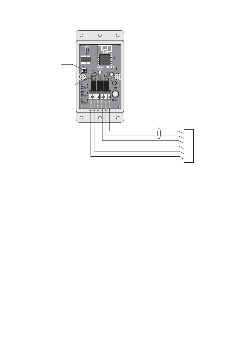
WR BASE-401-B
TRANSCEIVER
ACCESS COVER
REMOVED
iO-WRBBM
WIRELESS
BASE TRANSCEIVER
REV 1
REV 2
HVAC Controls

4. Make sure 2 VAC power is off before connecting wires to the base
transceiver.
5. The wiring diagram above illustrates the use of all channels for a 3 heat / 2
cool heat pump system. Depending on the application, not all channels may be
required.
iO-WRSM Satellite
Transceiver Module
1. The iO-WRSM Satellite
Transceiver is mounted near the
outdoor unit and should be
installed with the wiring access
hole at the bottom. The enclosure
has a moisture-proof perimeter
seal.
2. If 2 VAC is not available from
the indoor unit, a transformer must
be installed in the outdoor unit.
Refer to iO-WRSM wiring diagram.
3. When possible, mount the iO WRSM on a non-metalic surface close to the
outdoor unit to facilitate ease of wiring.
4. Follow the same wiring procedure as used for the iO WRBM.
TYPICAL WIRING FOR HEAT3/2COOL HEAT PUMP
C
R
W
O/B
Y2
Y1
G
C
R
W
O/B
Y2
Y1
G
HP THERMOSTAT
HP INDOOR UNIT
iO-WRBM
BASE
TRANSCEIVER MODULE
TERMINAL DESIGNATIONS
C = 24VAC COMMON
R = 24VAC HOT
W = AUXILIARY HEAT (REC)
O/B = REVERSING VALVE (SEND)
Y2 = SECOND STAGE COMPRESSOR (SEND)
Y1 = FIRST STAGE COMPRESSOR (SEND)
G = FAN
LED
BUTTON
REV 1
iO-WRSM
WIRELESS
SATELLITE TRANSCEIVER
HVHVAC ControlsAC Controls
Pairing Transceivers
Since the transceivers have been paired at the factory, it is highly unlikely that
they will require re-pairing. However, it may be necessary in the event one of the
transceivers requires replacement.
1. After all wiring is performed, apply 24 to both the base and satelliteVAC
transceivers.
2. The base transceiver will flash between red and green at a rate of 3LED
times per second. When in this mode, the base will broadcast a pair request
message once every 5 seconds until it receives a pair response from the satellite
transceiver.
3. The satellite will flash red every 3 seconds. Press and hold down theLED
pushbutton on the satellite transceiver until it starts flashing red and green every
3 seconds. Once this pattern appears on the , release the pushbutton.LED
4. Pairing is confirmed when both transceiver s go solid green. Once paired,LED
the transceivers will poll each other every 15 seconds regardless whether any
digital input signals are activated. The s will flash red rapidly when a dataLED
message is received and go solid red when a data message is sent.
Note: When using multiple iO- -401 wireless relays in the same location,WR
only power up one base and one satellite to be paired at a time.
Unpairing Transceivers
Unpairing a base and satellite transceiver is accomplished by holding down the
button while applying 24 and continuing to hold the button down for about 5VAC
seconds. While the button is held down, the will flash between red andLED
green 5 times per second. Once the unpairing process is complete, the willLED
flash as described in the pairing section. If the button is released prior to the
completion of the unpairing process, the transceivers will transition to the paired
mode, retaining their previous paired status.
TYPICAL WIRING FOR HEAT COOL HEAT PUMP3/2
C
R
O/B
Y2
Y1
W
HP OUTDOOR UNIT
iO-WRSM
SATELLITE
TRANSCEIVER MODULE
TERMINAL DESIGNATIONS
C = 24VAC COMMON
R = 24VAC HOT
W = ( )AUXILIARY HEAT SEND
O/B = ( )REVERSING VALVE REC
Y2 = ( )SECOND STAGE COMPRESSOR REC
Y1 = ( )FIRST STAGE COMPRESSOR REC
A separate transformer may
be required if 24 is notVAC
available from the indoor unit
LED
BUTTON

Loss of Communications
Each transceiver has a built in inactivity timer to detect a loss of communications.
If no data is received from a paired set for one minute, all outputs are turned off
and the LED will display solid red.
LED Behavior in Paired Mode
Once paired, the transceiver LEDs should be on solid green between data
commands or data response messages.
Solid Green - Last data transaction successful (within the last minute)
Solid Red - No reply from last data command message, or (satellite only)
no data command message received in the last 60 seconds.
Flashing Red - Data reply message received.
RSSI (Receiver Signal Strength Indicator)
The iO-WR transceivers are equipped with an RSSI function that provides an
indication of the receiver signal strength. The information is displayed on the LED
each time a data message is received. The LED will flash 1 to 5 times. The more
flashes, the stronger the signal. Once the red flashing is complete, the LED will
display solid green.
Specifications
Power:
Channels:
24VAC, 2.8VA
Base: 3 Send - 1 Receive Satellite: 3 Receive - 1 Send
Contact Rating: 1 Amp per channel
Frequency: 915MHz Operation
Range: Up to 100 ft.
Dimensions: 2-5/8” W x 5-1/8” H x 1-1/8” D
Compliance
The iO-WR Wireless Relay System has been tested and found to comply with
the limits for a Class B digital device, pursuant to part 15 of the FCC Rules.
These limits are designed to provide reasonable protection against harmful
interference in a residential installation. This equipment generates, uses and can
radiate radio frequency energy, and if not installed and used in accordance with
the instructions, may cause harmful interference to radio communications.
However, there is no guarantee that interference will not occur in a particular
installation. If this equipment does cause harmful interference to radio or
television reception, which can be determined by turning the equipment off and
on, the user is encouraged to try to correct the interference by one or more of the
following measures.
• Reorient or relocate the receiving antenna.
• Increase the separation between the equipment and receiver.
• Connect the equipment into an outlet or circuit different from that to which the
receiver is connected.
• Consult the dealer or an experienced radio/TV technician for help.
HVAC Controls
Indianapolis, IN 46237
www.iohvaccontrols.com
For Technical Support Call Toll Free: 866-225-5032
iO-06-1282-061819
Other manuals for iO-WR
1
Table of contents


