3
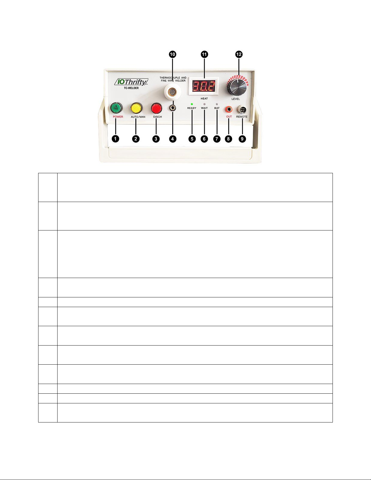
Front Panel Operations
1 Power Button – When the switch is turned on, the power button has two conditions: light or
no light, When the light is on, it indicates that the welder is operating from AC power. If the
light is off, the welder is operating from the internal rechargeable battery,
2 AUTO/MAN Button – Automatic or manual Argon flow control. When set to AUTO, the flow
of Argon is activated automatically when a weld is made. In the MAN (manual) mode, the
REMOTE switch is used to activate the flow of Argon. The manual mode is recommended.
3 DISCH Button – Discharge Button. When the welding energy is lowered, the DISCH
button is used to discharge the internal capacitor and release the excess energy. Hold the
button until the WAIT light turns on. Th
e HEAT meter will also change in real time.
Please use this button with care. DO NOT hold the button after the wait light comes on as
it may cause damage to the welder.
4 Electrode Clamp Port – This port accepts the connection of the included clamp which may
be used in place of the integral welding electrode.
5 READY Indicator – When the light is on, the welder is ready to be used.
6 WAIT Indicator – When the light is on, it indicates that welder is building charge and in a
non-welding state.
7 BAT Indicator – When the light is on, it indicates that the battery power is insufficient. Please
charge or connect the external power supply.
8 OUT Output Port – This port is used to connect the included welding pliers for the welding
operation.
9 REMOTE Port – Used to connect the included Foot Switch which controls the flow of Argon
gas when the AUTO/MAN switch is in the MAN state.
10 Welding Electrode – Electrode and protective cover used for welding.
11 Welding Power Indicator – Provides a real time display of the welding power level.
12 LEVEL Knob – Used to adjust the welding thermal energy. Since different thermocouple
wire sizes require different heat levels, you can adjust the amount of thermal energy.