9
Product Manual & Audio Set-up Guide
Pro Series Desktop Speaker Stands
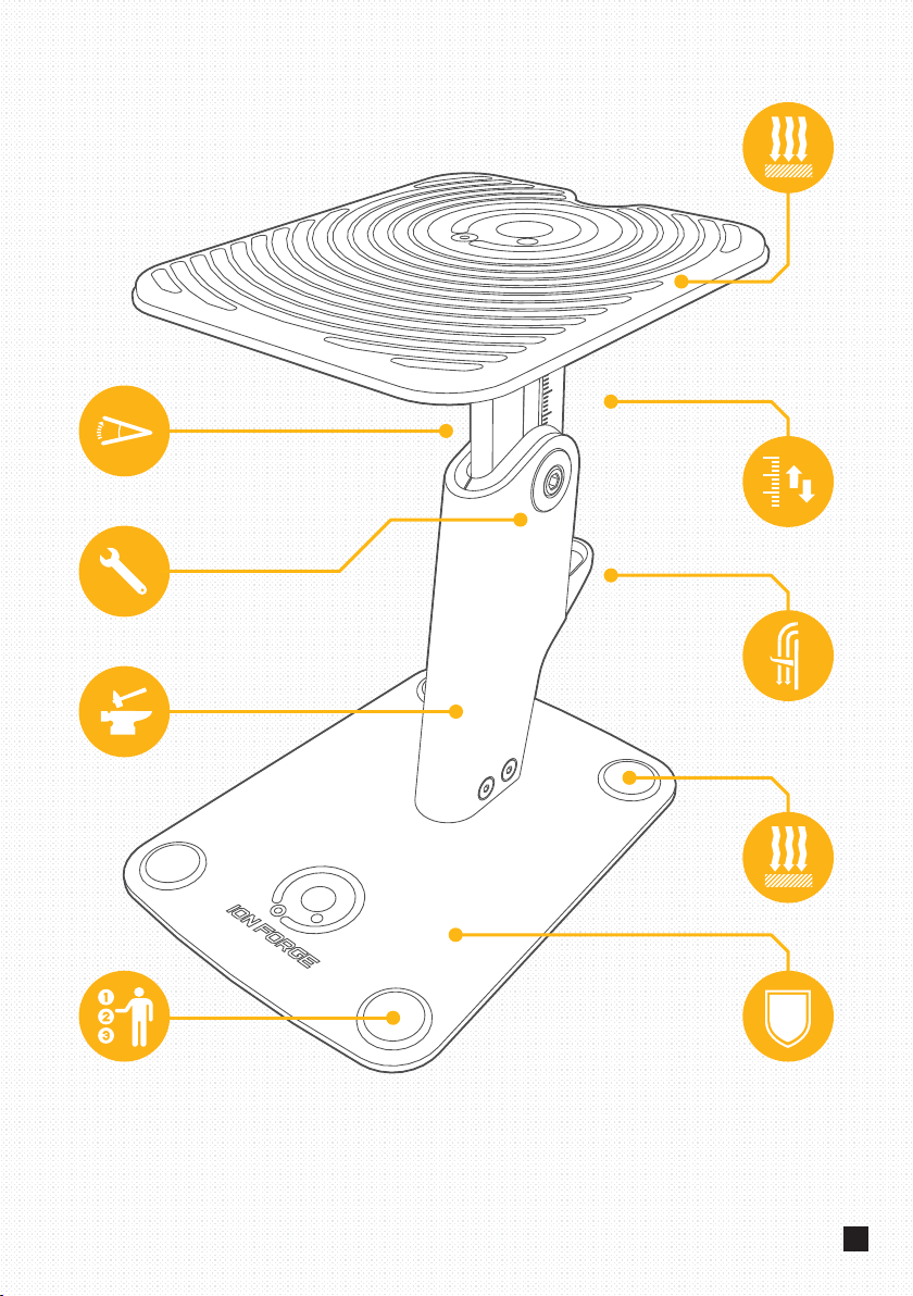
Technical Specifications
HEIGHT ADJUSTMENT RANGE (MIN) 200 mm (MAX) 285 mm
TOP SPEAKER PLATE SIZE (W) 170 mm (L) 200 mm
BASE PLATE SIZE (W) 175 mm (L) 225 mm
TILT ANGLE +/- 20 degrees
WEIGHT 2.6 kg (per stand)
RECCOMENDED WEIGHT LOAD CAPACITY Up to 10 kg (per stand)
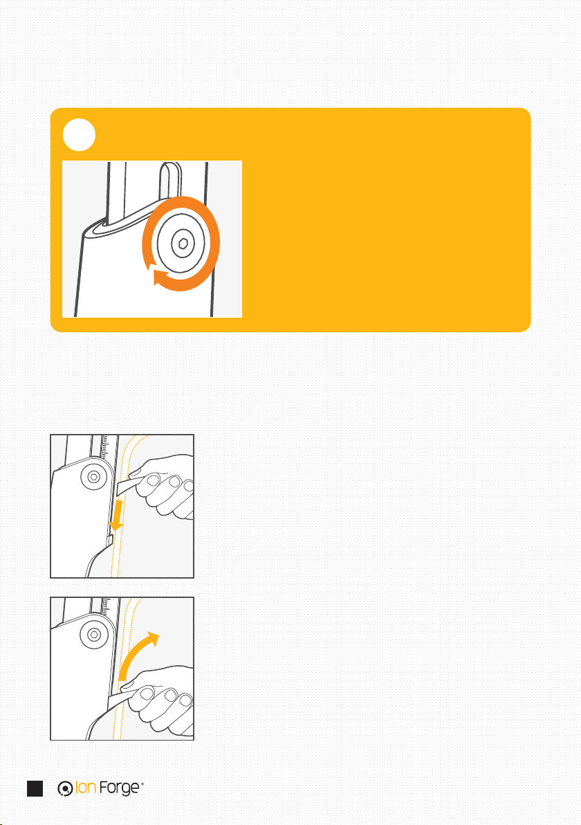
The bass response (and to some degree audio
image clarity) of a speaker can be tweaked to a
listener’s preference by changing the interface
material used to couple (or decouple) the speaker
with its base contact surface.
For this reason we have designed the silicone
vibration damping top mat component of the Pro
Series Desktop Speaker Stands to be removable
to allow you to sit your speakers directly on each
stand’s top plate surface, or to allow you to use
alternative speaker-to-stand coupling interface
options such as foam isolation pads, spikes or
other custom designed solutions.
While we think the silicone vibration damping
top mat works beautifully, we recommend that
you experiment and find the speaker-to-stand
coupling interface option that for your specific
speaker configuration and listening needs works
best for you.
Vibration Damping Top Mat