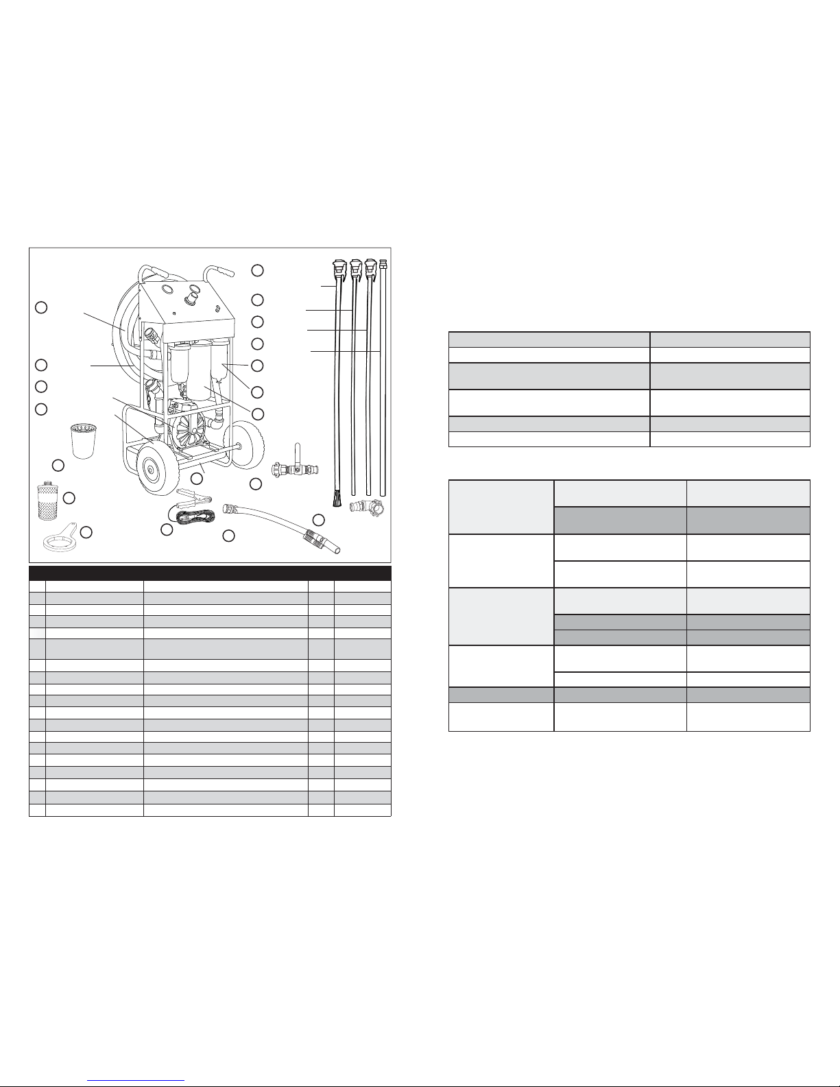
iPA 9046F User manual

Innovative Products of America®Incorporated
234 Tinker Street, Woodstock, NY 12498
888-786-7899 • 845-679-4500 • www.ipatools.com
(OEM) Original Equipment Manufacturer USA
LIMITED TWO-YEAR WARRANTY
© 2018 Innovative Products of America®Incorporated. All rights reserved. This material may not be reproduced, displayed,
modified or distributed without the express prior written permission of the copyright holder. For permission, contact [email protected].
#9046F/#9046H/#9046FH-MANUAL-VA-03-14
#9046F/#9046H/#9046FH PNEUMATIC TANK SWEEPER®
Innovative Products of America®Incorporated has established a Limited Two-Year
Warranty Policy for the Pneumatic Tank Sweeper®.
Limited Two-Year Warranty/Return/Replace Policy: The product is covered for two
years from the date of original user purchase under the stipulations of the Standard
Warranty.
The product is warranted to be free from defects in workmanship or material. If there
is a problem due to workmanship or material defect, Innovative Products of America®
will repair or replace the product within 24-working hours after it is received by the
IPA®Repair Service Center. In the event it is determined that the product has been
tampered with or altered in any way, the warranty is void and all claims against the
product will not be honored. The Warranty Repair/Return procedures require that the
proof of purchase must be established (either by warranty card from the seller or
by point of purchase receipt/invoice) and the manufacturer makes every attempt to
return ship the product within three business days from the receipt of the returned
product, freight prepaid.
If it has been determined that the tool has been damaged due to misuse, Innovative
Products of America®will repair the tool at a cost we deem reasonable and these
charges will be the responsibility of the user. We truly want you to be happy with our
products, so if you have any questions, call us toll free at 888-786-7899.
Operator’s Manual
#9046F/#9046H/#9046FH
PNEUMATIC TANK SWEEPER®
Innovative Products of America®Incorporated
845-679-4500 • 234 Tinker Street, Woodstock, NY 12498 • www.ipatools.com
© 2018 Innovative Products of America®Incorporated. All rights reserved. This material may not be reproduced, displayed,
modified or distributed without the express prior written permission of the copyright holder. For permission, contact [email protected].
Not for Use with Gasoline or Other Highly Volatile Fluids
MAD
E
IN
USA

2
LETTER FROM THE PRESIDENT OF IPA®
My name is Peter Vinci and I am the president of IPA®. I would like to thank you for
your interest in IPA®’s product line and share my commitment to you, our products
and our policies. In today’s world, we have all experienced the lack of service and
consideration demonstrated by many companies after you buy their products. They
say whatever they can to make the sale, and then it’s like pulling teeth to get any
service response out of them. I know this myself firsthand and because of this, I
want to be sure that your experience with IPA®meets your expectations and that
IPA®never disappoints you with our service or customer response.
To prove my commitment to you, if for any reason, you are not happy with one of
our products – or more importantly, with the response from our customer service
department, or any member of the IPA®team – I invite you to contact me directly
is more important to me than the sale itself. We will not be in business for long if we
don’t make you completely happy with our products and service. I want IPA®to be
different and be known for its quality and service.
With that said, please take a look at our product line. You will see innovative first time
products that were created to help you do your job faster and better than before.
I would also like to invite you to critique our products. If you can think of a better way
to make them or changes that will make them work better, please contact me directly
and I will be sure to look into it. If you have an innovation and would like some
feedback, give me a call.
From all of us at IPA®, we thank you for taking the time to review our product line
and wish you and your family the very best of everything.
Peter Vinci
President
IPA®
www.ipatools.com
Toll Free: 888-786-7899
Phone: 845-679-4500
Fax: 845-679-4600
(OEM) Original Equipment Manufacturer USA
11
NOTES

10
NOTES
3
IMPORTANT SAFETY INSTRUCTIONS
IT IS IMPORTANT TO READ, UNDERSTAND AND FOLLOW ALL SAFETY
MESSAGES AND INSTRUCTIONS PRINTED IN THIS MANUAL AND ON THE
EQUIPMENT BEFORE OPERATING. IF SAFETY INFORMATION IS NOT HEEDED,
SERIOUS INJURY OR DEATH TO THE OPERATOR OR BYSTANDERS MAY OCCUR.
DANGER
Indicates a hazardous situation, if not avoided, will result in death or serious injury.
The possible hazards are shown in the adjoining symbols or explained in the text.
WARNING
Indicates a hazardous situation, if not avoided, could result in death or serious injury.
The possible hazards are shown in the adjoining symbols or explained in the text.
CAUTION
Indicates a hazardous situation, if not avoided, may result in minor or major injury.
The possible hazards are shown in the adjoining symbols or explained in the text.
THE FOLLOWING SAFETY ALERT SYMBOLS ARE USED IN THIS MANUAL.
SYMBOL 1: Potential burn hazard. Sparks from electrical shorts can ignite
flammable liquids such as fuel or oil. Heat from electrical overloads can cause fire
hazards.
SYMBOL 2: Potential explosive air hazard. Pneumatic pressures used with this
equipment can cause explosive failures on damaged equipment.
SYMBOL 3: Potential eye hazard. Wear OSHA approved safety glasses. Battery
acid and high air pressures create hazardous situations for eyes.
SYMBOL 4: Potential chemical burn hazard. Wear protective gloves. Battery acid
is corrosive and can cause skin damage.
SYMBOL 5: Potential fire hazard. Use caution with flammable liquids such as fuel
and oil. Electrical shorts can ignite flammable liquids and wiring.
NOT FOR USE
WITH GASOLINE

4
WHAT’S INCLUDED
Use the Provided Reference Numbers When Ordering Products and Parts Above • Toll Free: 888-786-7899
IPA® Part # Description Qty. Unit
A#9046-INHOSE-AS 12' Input Hose 1 F/H/FH
B#9046-OUTHOSE-AS 12' Output Hose 1 F/H/FH
C#PMP00004 25 gpm Pneumatic Pump 1 F/H/FH
D#7900K-WHLKIT Rubber Pneumatic Wheel Kit 1 F/H/FH
E#FIL00010 10-Micron Water-Blocking Filter 2 H/FH
F#FIL00003 30-Micron Particulate-Blocking Filter for
Diesel and Fuel 2 F/FH
G#FIL00001A 17-Micron Water-Blocking Filter 1 F/FH
H#FIL00002A 178-Micron Wire Mesh Filter w/ Housing 1 H/FH
I#FIL00002 381-Micron Wire Mesh Filter w/ Housing 1 F/FH
J#FIL00005 Filter Wrench 1 F/H/FH
K#9046-BRWAND-AS 5' ¾" Dia. Flex Wand w/ Flow-Through Brush 1 F/FH
L#9046-OUTPUT2-AS 5' ½" Dia. Flex Wand 1 F/H/FH
M#9046-OUTPUT-AS 5' ¾" Dia. Flex Wand 1 F/H/FH
N#9046-INPUT-AS 5' 1" Dia. Rigid Wand 1 F/H/FH
O#9046-VALVE-AS Quick-Disconnect Ball Valve 1 F/H/FH
P#007900K-2BCHAS Chassis Ground Cable 1 F/H/FH
Q#9046-90DEG-AS Quick-Disconnect Right Angle 1 F/H/FH
R
#9046-HSADPTR-AS
Quick-Disconnect Adapter Hose 1 H/FH
S
#9046-3
Drip Pan 1 F/H/FH
A 12' Input
Hose
B 12' Output
Hose
E 10-Micron
Water-Blocking
Filter
J Filter Wrench
G 17-Micron
Water-Blocking Filter
C 25 gpm
Pneumatic Pump
D Rubber Pneumatic
Wheel Kit
(Image is not actual representation of final product. Exact location and style of fittings may vary.)
O Quick-Disconnect
Ball Valve
Q Quick-Disconnect
Right Angle
S Drip Pan
F 30-Micron
Particulate
Blocking Filter
K 5',¾" Dia. Flex
Wand with Flow-
Through Brush
L 5',½" Dia.
Flex Wand
M 5',¾" Dia.
Flex Wand
N 5',1" Dia.
Rigid Wand
P Chassis
Ground
Cable
R Quick-Disconnect
Adapter Hose
H
178-Micron Wire
Mesh Filter
or
I
381-Micron Wire
Mesh Filter
9
The pump continues
operating although the
outlet valve is closed.
There is a leak at some point
of the outlet circuit. Verify and tighten or repair.
Check if valve balls and/or
seats are worn. Replace the worn items.
The pump does not
operate or cycles
once and stops.
Air valve is stuck or dirty. Disassemble and clean the
air valve.
Check if valve ball is severely
worn and wedged in seat. Replace ball and seat.
The pump operates
erratically.
Clogged suction line. Verify and clean the
suction line.
Sticky or leaking valve balls. Clean or replace.
Diaphragm ruptured. Replace diaphragm.
Air bubbles in fluid.
Suction line loose or
damaged.
Verify and tighten or
replace.
Diaphragm ruptured. Replace diaphragm.
Fluid in exhaust air. Diaphragm ruptured. Replace diaphragm.
The pump exhausts
air at stall. Worn parts in air valve. Repair or replace.
TROUBLESHOOTING
Ratio 1:1
Air Pressure Operating Range 22 to 115 psi (1,5 to 8 bar)
Maximum Suction Head 14.76 ft (4,5 m) dry
22.97 ft (7m) wet
Weight 15.87 lb (7,2 kg) metallic series with
Aluminum body
Fluid Inlet (single inlet) 1"BSP/NPT (F) and flange)
Fluid Outlet 1"BSP/NPT (F) and flange
PUMP TECHNICAL INFORMATION
AIR-OPERATED DIAPHRAGM PUMP DESCRIPTION
1:1 ratio, air-operated diaphragm pump with aluminum body and Buna N
diaphragms. This pump is recommended for transferring oil or evacuating waste oil.

8
OPTIONAL FILTERS
(A) #FIL00003 30-Micron Particulate-Blocking Filter
(A) #FIL00010 10-Micron Water-Blocking Filter
(A) #FIL-02WB 2-Micron Water-Blocking Filter
(A) #FIL-02PT 2-Micron Particulate-Blocking Filter
(B) #FIL00001A 17-Micron Water-Blocking Filter
(C) #FIL00004 381-Micron Wire Mesh Filter
(C) #FIL00013 178-Micron Wire Mesh Filter
NOTE: Each unit includes one extra filter for each option available to that unit.
Additional quantities are available.
ACCESS WANDS
The #9046 Pneumatic Tank Sweeper®series offers four wands for input and output
depending on the unit. See below for a description of each wand.
1. 5' Long x 1" Dia. Rigid Wand: Should be used on the input side for accessing
55-gallon drums and other stationary tanks.
2. 5' Long x ¾" Dia. Flex Wand: Can be used on either input or output side.
3. 5' Long x ½" Dia. Flex Wand: Only used on the output side to avoid restricting
flow to the pump. The ½" wand is traditionally used for blasting the inside of tank
walls with a higher pressure.
4. 5' Long x ¾" Dia. Flex Wand w/ Flow-Through Brush: The flow-through brush is
removable and should only be used with extreme caution to avoid losing the brush
inside a fuel tank. Be sure to securely tighten the brush to the wand before use.
(Comes with #9046F and #9046FH only. Available separately for #9046H.)
ABC
CHANGING FILTERS
1. If output flow stops while pump is still active, the filters may be clogged. Verify
the filters are clogged by disconnecting the air supply and observing OUTPUT/
FILTER PRESSURE Gauge. If the filters are clogged, the gauge will continue
displaying a high-pressure reading.
2. Prior to changing filters, be sure the drain pan is in place. Dissipate any remaining
pressure in the system by opening the petcock at the base of the clear filter housing and
Valves 2 and 3.
Valve 2
Valve 1
Valve 3
5
MUST READ BEFORE USE
This diaphragm pump is meant for use with liquids only. DO NOT suck up leaves,
gravel or other solids. Doing so will void the warranty.
SUMMARY
The Pneumatic Tank Sweeper®is a portable system designed for recovering and
salvaging hydraulic/diesel fuel and oil. This system is offered in three model types:
#9046F - for filtering diesel and fuel oil, #9046H - for filtering hydraulic oil, and
#9046FH - for filtering diesel fuel, fuel oil and hydraulic oil. Specific options such as
filters, wands and adapters are included for each model type. Each model utilizes
diverter valves, which allow the user to bulk transfer without filtering for removing
contaminants from the bottom of the tank where the majority of the sludge, water
and debris settle. It also transfers through the filters for the purpose of polishing
the fuel/oil, which is typically performed as a scheduled preventative maintenance
procedure. The provided input and output wands are specifically built for these
applications.
SET-UP INSTRUCTIONS
1: ASSESSING THE CONDITION OF THE FUEL/OIL
It is recommended that you visit the site 48 hours before tank sweeping to prepare
the tank and assess the site condition. Using the optional IPA®#9042 Sample Stick,
insert the tool all the way down to the bottom of the tank you are cleaning. Draw the
piston shaft up enough to get a good sample of the fuel (approximately 12"). Remove
the Sample Stick and note the amount of water and crud at the bottom of the tank.
It is recommended that you transfer the sample into a glass jar and allow the various
contaminants to settle and separate for 24 hours. This will give you an idea of the
fuel condition inside the tank and the amount/type of the contaminated fuel.
2: KILLING MICROBIAL GROWTH
Add an algae biocleaner or equivalent to the tank in appropriate amounts. Using the
Sample Stick, stir the tank briskly to mix the algae cleaner into the oil. After 48 hours,
the algae should be killed off and the tank is now ready for sweeping. If convenient
and safe, you may use a small jack to elevate the tank a few degrees on one side to
allow the majority of contaminates to collect on one end of the tank. This is the end
you will choose to sweep.
3: REMOVING SLUDGE AND DEBRIS FROM BOTTOM OF TANK
WARNING: Do NOT hook up air to cart until set-up is complete!
1. Set up your Tank Sweeper®near the tank to be cleaned, allowing enough room
for the input hose to reach the tank.
2. Install the output hose to the bulk/unfiltered output quick-disconnect fitting
located on the side of the Tank Sweeper®.
3. Attach the output wand to the other end of the hose and insert into a 55-gallon
drum (Note: Use a clean and leak-free 55-gallon drum).
4. Connect the desired wand to the input hose via couplers.
WARNING: Be sure to use the locking pins on all the quick-disconnect
fittings so that the locking levers do not vibrate loose.
5. Insert the wand all the way down to the bottom of the oil/fuel tank you are cleaning.

6
6. Be certain to follow the ball/valve instructions indicated on the front panel of the
unit. Attach air supply line to the inlet air on the pump assembly. Do not turn the
air ball valve on yet.
7. Set the air pressure to 50 psi. Air operating range is from 50-100 psi. A setting
of 50 psi is recommended to give the operator more control of the sweeping
operation. Do not turn on the air ball valve yet.
NOTE: When ready to operate the Tank Sweeper®, be sure to check all connections
for leaks and be prepared to shut down the Sweeper®. Have your emergency spill kit
available and in reach.
NOTICE: Especially during first use, it is best to have this operation performed by
two people—one operating the air supply and the other person sweeping the tank.
8. Once the pump is pumping, the Tank Sweeper®will begin to remove the bottom
contents of the tank where the majority of fuel contaminants exist, i.e., water,
crud, algae and rust. The Tank Sweeper®operator should move the rigid wand in
a sweeping motion back and forth across the bottom of the tank. You may first
observe water, then black sludge-like-debris, and then the fuel/oil should begin to
slowly change color to a healthy looking state. Being careful not to overflow the
55-gallon drum, quickly move the wand to a position where contaminants are still
being suctioned. Repeat this sweeping function until only clean fuel is removed.
It may be necessary to use two 55-gallon drums depending upon the amount of
contaminates found.
NOTE: Be mindful of the 55-gallon drum level and be sure not to overfill. Have your
emergency spill kit ready and available in case of a spill. Leave sufficient air space
for expansion.
PRIMING
1. Close all valves and adjust regulator to zero.
2. Insert input hose into clean fuel source (use wands when necessary).
3. Connect output hose to FILTERED OUTPUT on cart.
4. Connect primer adapter to end of output hose.
5. Open Valve 2.
6. Open SHOP AIR Valve.
7. Slowly increase regulator pressure to desired output.
Valve 2
Pneumatic
Diaphragm
Pump
Primary Filter
Secondary Filter
Filtered Output
Input
7
FILTERING/POLISHING
1. Close all valves and adjust regulator to zero.
2. Insert desired wand into bottom of dirty tank and connect to input hose.
3. Connect output hose to FILTERED OUTPUT on cart.
4. Connect other end of output hose to desired wand and insert into desired
destination.
5. Open Valve 2.
6. Open SHOP AIR Valve.
7. Slowly increase regulator pressure to desired output.
BULK TRANSFER
1. Close all valves and adjust regulator to zero.
2. Insert input hose into fuel or oil source (use wands when necessary).
3. Connect output hose to UNFILTERED (BULK) OUTPUT.
4. Open Valve 1.
5. Open SHOP AIR Valve.
6. Slowly increase regulator pressure to desired output.
Valve 2
Pneumatic
Diaphragm
Pump
Primary Filter
Secondary Filter
Filtered Output
Input
Valve 1
Pneumatic
Diaphragm
Pump
Input
(Bulk) Output
Unfiltered
This manual suits for next models
2
Table of contents
Other iPA Blower manuals