IPcopter tVip_2 User manual

Manual tVip_2
10/2011
__________________________________________________________________________
1/34
tVip_2
Installation and Operation Manual
Please note, that the internet access must not be
used near airports (within a radius of 5 km)!

Manual tVip_2
10/2011
__________________________________________________________________________
2/34
Important Notes
•Please be informed, that this product is designed for use on RVs,
campers or caravans. The use of the system for any other purpose is
not permitted.
•Any modification of the system, e.g. by change of reflector, use of
other receivers or LNBs, use of other than the delivered cables or
other modifications results in loss of warranty and loss of permission
to use the internet access mode.
•Please make sure, that the system is installed according to the
installation manual and according to the guidelines of the automotive
industry.
•The system shall be used according to the operation instructions.
•Never move your camper without checking, if the antenna is in
parking position. Please implement an appropriate warning note on
your dashboard or the automatic warning system delivered with the
antenna system.
•Your camper shall not be cleaned with mounted antenna in a drive
through car wash or with a high pressure cleaner. In case of such type
of cleaning please remove your antenna in advance and seal the
antenna mounting tube.
•Above windspeeds of 60 km/h (storm force 7) the antenna shall be
folded into parking position.

Manual tVip_2
10/2011
__________________________________________________________________________
3/34
Contents:
1. Installation Manual........................................................................................................... 4
1.1 Deliverables...................................................................................................................... 4
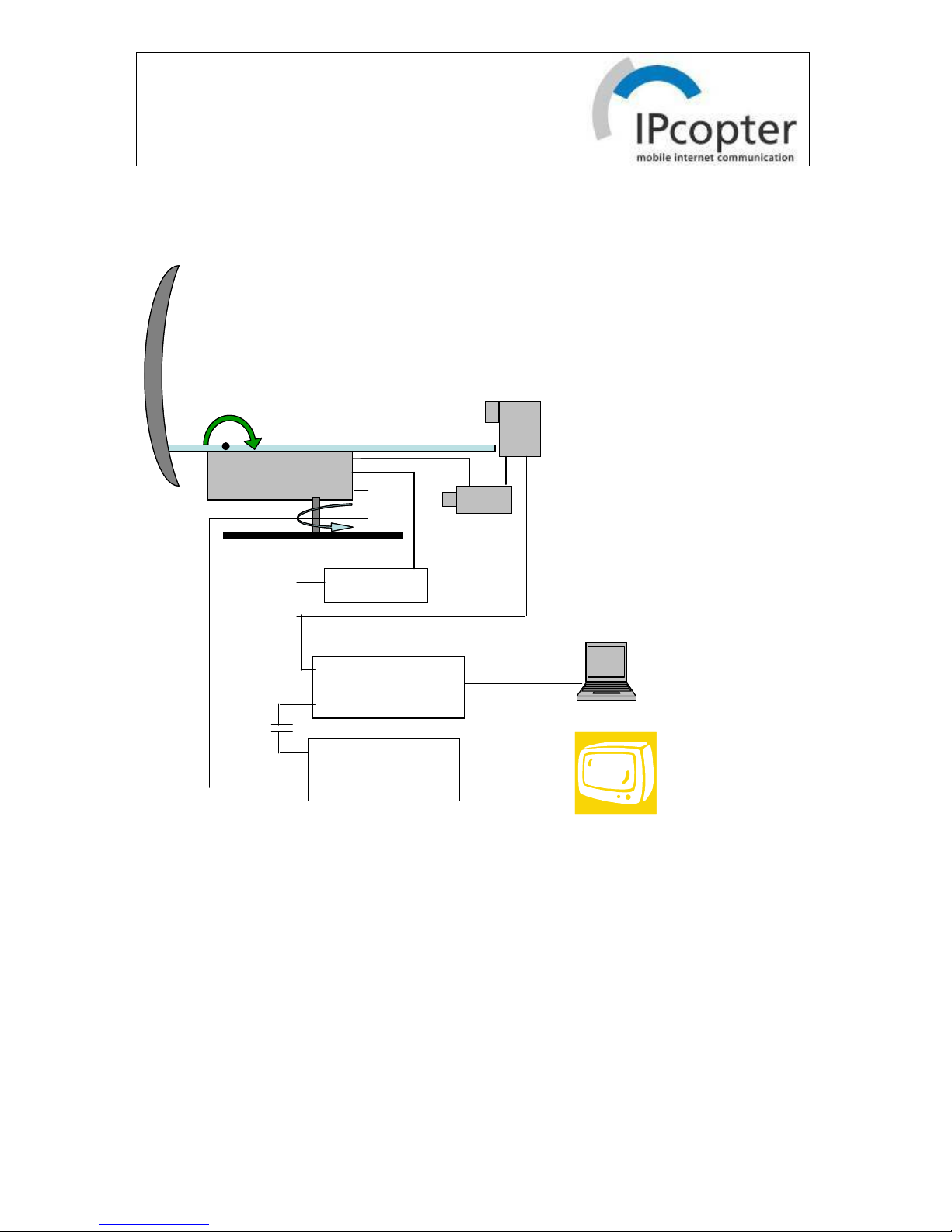
1.2 Blockdiagram ................................................................................................................... 6
1.3 Installation Antenna Systemt ........................................................................................... 7
1.3.2 Preparation of motor unit ................................................................................... 7
1.3.3 Outdoor Installation of Antenna......................................................................... 9
1.3.4 Mounting of Reflector...................................................................................... 10
1.3.5 Indoor adjustment of disk with manual adjustment symbols ........................... 10
1.3.6 Cabling .................................................................................................................... 11
1.4 Installation Indoor Units................................................................................................. 11
1.4.1 Standard Installation without Fritz!Box.................................................................. 11
1.4.2 Installation incl. Fritz!Box ...................................................................................... 12
1.4.3 Power Supply ................................................................................................... 12
1.5 Commissioning............................................................................................................... 12
2. Operation Manual .......................................................................................................... 14
2.1 General ........................................................................................................................... 14
2.2 Manual preadjustment .................................................................................................... 14
2.3 Usage of remote Control ................................................................................................ 15
2.4 TV Mode ........................................................................................................................ 15
2.4.1 Pointing of Antenna to TV Satellite I...................................................................... 15
2.4.2 Operation of TV Receiver ....................................................................................... 17
2.5 Internet Mode ................................................................................................................. 18
2.5.1 Pointing of Antenna to Internet Satellite................................................................. 18
2.5.2 Operation of Satellite Modem ................................................................................. 20
2.5.3 Connection and Configuration of Computer or W-LAN Router ............................ 20
2.5.4 Booking and Controlling of Internet Subscription.................................................. 21
2.5.5 Load Balancing ....................................................................................................... 22
2.5.6 Expert Mode: Modem Web Interface...................................................................... 25
2.5 Parking ........................................................................................................................... 25
3. Frequently Asked Questions ........................................................................................... 27
3.1 Installation...................................................................................................................... 27
3.2 Antenna .......................................................................................................................... 28
3.3 TV................................................................................................................................... 30
3.4 Internet ........................................................................................................................... 30
4. Technical Data................................................................................................................... 32
5. Declaration of Conformity ................................................................................................ 33
6. Contact................................................................................................................................ 34

Manual tVip_2
10/2011
__________________________________________________________________________
4/34
1. Installation Manual
1.1 Deliverables
1
2
4
3
6
5
8
79
12
10
13
1
2
4
3
6
5
8
79
12
10
13
Fig. 1: Deliverables

Manual tVip_2
10/2011
__________________________________________________________________________
5/34
Pos. Description Quantity
1 2-axis Motor, iLNB (Option Internet Kit), TV LNB, feedarm,
reflector backstructure, cabling
1
2 Parabolic reflector
3 Roof mounting plate 1
4 Receiver + Remote Control (Dreambox) 1
5 IPcopter Modem + Ethernet cable (Option Internet Kit) 1
6 DC-Block + short coax cable 1
7 Antenna mount with manual Az fix 1
8 Cable clamp 1
9 Beeper Antenna Security Control
10 Installation and Operation Manual 1
11 Tripod + Cable extensions (Option, not in the picture) 1
12 Switch for second TV Receiver (Option)
13 Different Screws

Manual tVip_2
10/2011
__________________________________________________________________________
6/34
1.2 Blockdiagram
TV Receiver
Dreambox
antenna controller
in
out
Interactive LNB
Internet
Modem
Rx
Tx
Ethernet
Rx Tx
DC Block
TV LNB
with
integrated
DiseqC switch
STB LNB
Antenna Security
Control
ignition
TV Receiver
Dreambox
antenna controller
in
out
Interactive LNB
Internet
Modem
Rx
Tx
Ethernet
Rx Tx
DC Block
TV LNB
with
integrated
DiseqC switch
STB LNB
Antenna Security
Control
ignition
Fig. 2: Blockdiagram

Manual tVip_2
10/2011
__________________________________________________________________________
7/34
1.3 Installation Antenna Systemt
1.3.1 Space Requirements, General Remarks
The parking position of the antenna defines the space, which is necessary for mounting the
antenna on the roof. In general we recommend, that the antenna is mounted by an expert.
70 cm
45 cm
26 cm
17 cm
92 cm
75 cm
Fig. 3: Space requirements
Please select carefully the location of your antenna:
•Make sure, that the rotating antenna does not touch any other roof mounted equipment
•Make sure, that the hole does not damage any installation in the vehicle
•Make sure, that the indoor part of the antenna axis is located on a suitable position for
simple operation.
If you have any doubts, please ask your dealer or vehicle manufacturer
IPcopter is not responsible for any damages caused by the installation of the system.
1.3.2 Preparation of motor unit
Before installation the motor unit shall be moved to an upright position of the reflector. Please
connect the Rx line to the Dreambox and push the blue button on the remote control of the
Dreambox. As soon as the antenna backstructure is rectangular to the motor box please
push the Exit button to stop the movement. Please see Fig. 4

Manual tVip_2
10/2011
__________________________________________________________________________
8/34
Blue button: Elevation
of antenna backstructure
Exit:
Stop movement
Cable without black mark
Dreambox
Installation position of
of antenna backstructure
Fig. 4: Preparation of motor unit

Manual tVip_2
10/2011
__________________________________________________________________________
9/34
1.3.3 Outdoor Installation of Antenna
Step 2:
Drill 32mm hole
through the roof.
(provide counter-
pressure from
inside!)
Please make a
break of about 20
minutes.
Step 1:
Select location and
mark position of center
hole and mounting
plate. Please ref. To
Fig. 3
Step 3:
Sandpaper and clean
carefully the mounting
area on the roof and
the mounting plate
with Aceton
Step 4:
Cover in uninterrupted
spirals the mounting
area on the roof with
SikaFlex
Step 6:
Mount antenna
Step 6:
Press mounting plate
on roof carefully.
Gap for Sikaflex
between roof and
mounting plate at
least 2 mm
Step 7:
Fix antenna mount
inside
Disk with symbols for
rough positioning
Knurled Screw
Step 5:
Fix antenna mount on
mounting plate
Fig. 4: Installation Antenna

Manual tVip_2
10/2011
__________________________________________________________________________
10/34
1.3.4 Mounting of Reflector
After the installation the reflector can be mounted on the according backstructure: Please fit
the reflector at first on the upper two screws, which are already inserted on the
backstructure. Afterwards please fix the lower two screws and finally the upper two screws.
Fig. 5: Mounting of Reflector
1.3.5 Indoor adjustment of disk with manual adjustment symbols
1) turn Antenna into parking position
2) turn disk until the red point is below the open clamp
3) fix disk with
knurled screw
Fig. 6: Adjustment of disk with manual adjustment symbols

Manual tVip_2
10/2011
__________________________________________________________________________
11/34
1.3.6 Cabling
After mounting of the antenna the cables shall be fixed. The twin coaxial cable shall be
rotated twice around the motor axis with a wide radius, approximately the radius of the
mounting plate, and then fix the cables with the cable clamp, please see fig. 5.
The two coaxial cables can be extended to a max. length of 20 m. The cables can be led
from the roof to inside by simple holes, sealed with Silicon, or better by a roof penetration.
Fig. 7: Fixing of antenna cables.
1.4 Installation Indoor Units
1.4.1 Standard Installation without Fritz!Box
The figure below shows the indoor cabling for the TV+Internet system. The coaxial cable
with the black mark is the transmit cable and shall be connected to the Tx port of the modem.
IPcopter
Internet
Modem Dream
TV Receiver/
Antenna Controller
DC Block
Black marked
Coaxial cable
From
Antenna
Alternatively
also SCART
can be used
IPcopter
Internet
Modem Dream
TV Receiver/
Antenna Controller
DC Block
Black marked
Coaxial cable
From
Antenna
Alternatively
also SCART
can be used
Fig. 8: Installation Indoor Units

Manual tVip_2
10/2011
__________________________________________________________________________
12/34
1.4.2 Installation incl. Fritz!Box
IPcopter Modem
LAN Cable
Standard Phone
or DECT Basestation
12V
Please use only the LAN 1 input
to connect the IPcopter Modem!
Fig. 9: Installation Indoor Unit incl. Fritz!Box
1.4.3 Power Supply
Ideally the system is supplied directly from the suitable car battery. Please make sure, that
the supply cables have a diameter of at least 4 mm.
1.5 Commissioning
It is strongly recommended to commission the system after installation, even, when the
system is installed by an experienced dealer. Please find below the recommended
commissioning procedures. All tests shall be “passed”
Before commissioning it is strongly recommended to read the Operation Manual (section 2 of
this document). Please follow all steps of the commissioning procedure on the TV Screen.
No. Description of Test Passed/
failed
1 Move antenna to park position (red button): In park position feedarm shall
not move and not be pressed too much on reflector
2 Point to TV satellite I (yellow button). Watch your favourite TV channel
3 Point to TV satellite II (green button). Watch your favourite TV channel
4 Point to Internet satellite (blue button).

Manual tVip_2
10/2011
__________________________________________________________________________
13/34
5 Connect your Laptop.
Google some websites; Send e-mail
6 Browse to 192.168.1.1 Read at “Demodulator Es/No = ?? dB At clear
sky the value shall be above 9,5 dB
7 Move antenna to park position (red button)
8 Point to Internet satellite (blue button). Max. number of Scans until
satellite detection: 3
9 If Fritz!Box with VoIP account is installed: Please make a phone call and
receive a phone call. Please check wireless internet connection
10 Move antenna to park position (red button)

Manual tVip_2
10/2011
__________________________________________________________________________
14/34
2. Operation Manual
2.1 General
The duration of the pointing process depends mainly on the distance to your last location:
Depending on the location the elevation of the antenna is different: The satellite is stationary
located on an equator of a radius of 40.000 km. If you would stay directly below the satellite
on the equator, your antenna would look vertically up to the satellite. If you would stay far in
the north, the antenna would look nearly horizontally to the satellite. The antenna system
stores the elevation angle of the last pointing process. If you stay on the same location or did
not move too far (< 300 km), the satellite will be detected at the first, at least at the third scan.
If the location has been changed significantly, it can take several scans until the satellite is
detected.
Especially at change of scan direction or at switch from vertical to horizontal movement
sometimes longer interruptions of movement occur. This has to do with the logic of the
scanning process and is not a fault.
It can take more than 10 minutes until pointing is completed.
Before pointing please attend the following:
- Pointing at strong wind might take more time than usual
- In Winter please make sure, that not too much snow is on the parked antenna
- It is recommended to switch on the TV to follow the pointing process.
- Please check, if the distance of the unfolded antenna to trees or other obstacles is far
enough. A crash during pointing process can cause damages on the antenna.
- Please check, if there is no obstacle on the line of sight to the satellite.
2.2 Manual preadjustment
1) Turn antenna to the symbol,which
corresponds roughly to the direction of your RV
2) Lock Clamp
Fig. 10: Manual East-West preadjustment.

Manual tVip_2
10/2011
__________________________________________________________________________
15/34
The Azimuth (East – West) direction has a limited motion range of +/- 65 degrees. Therefore
the antenna roughly has to be manually preadjusted in East –West direction following Fig.10.
Fig. 10 shows the preadjustment on the example of a RV, which is positioned with the
entrance/awning direction south.
The process is the same, if the antenna is operated on a Tripod.
2.3 Usage of remote Control
Parking
TV Satellite II
HotBird
UK: Astra 2
Internet
TV Satellite I
Astra 1
Stop
Fig. 11: Remote Control of TV Receiver/Antenna controller (Dreambox)
2.4 TV Mode
The process of pointing can be followed on the TV screen. Please find in the following the
according screenshots.
2.4.1 Pointing of Antenna to TV Satellite I

Manual tVip_2
10/2011
__________________________________________________________________________
16/34
Fig.12: Moving to last position of TV satellite I
For pointing to the TV Satellite I please push the orange button on the remote control (for TV
satellite II please push the green button). At first you see the above picture: It means, that the
antenna is moving to the last position of the TV satellite, in this case Astra 19,2 degrees
East. As soon as the satellite is detected, a green check mark will be visible in the box
beside “Lock” and “Sync”. The fine pointing process starts. After successful fine pointing the
new position of the TV satellite is stored, please see screenshot below. After the automatic
save of the satellite position you can watch TV.
Fig. 13: Save of satellite position after successful pointing
If the antenna does not find the satellite on the previous position, caused e.g. by a different
location, the search process according to the screenshot below starts. In the worst case
several scans are necessary until the antenna finds the satellite. As soon as the satellite is

Manual tVip_2
10/2011
__________________________________________________________________________
17/34
detected, a green check mark will be visible in the box beside “Lock” and “Sync” and fine
pointing starts as described above.
Fig. 14: Clockwise scan as part fo pointing process
If during the pointing process the AGC value or/and the SNR value is far below
60%, a cable or connector problem may exist. Please check all cables and
connectors.
2.4.2 Operation of TV Receiver
A separate manual for the TV receiver is part of the deliveries. However, because the
software of the receiver is modified by IPcopter, in the following some functionalities and
features are outlined, which are different to the manual of the Dreambox:
•The functionalities of the Infobar (section 17) are replaced by functionalities for antenna
control.
•Please do not change the Skin, because this could lead to a full stop of the Dreambox
internal Enigma Software and consequently the system is not usable any more.
•It is not possible to install plugins.
•The reset to factory settings may cause the loss of the channel list configuration.
•The installation of a software image not provided by IPcopter causes the the distortion of
the control software and the system does not work any more.
Please avoid any configuration changes of the Dreambox. IPcopter is not responsible
for malfunctions caused by such configuration changes.

Manual tVip_2
10/2011
__________________________________________________________________________
18/34
2.5 Internet Mode
2.5.1 Pointing of Antenna to Internet Satellite
The pointing on the internet satellite, which is the Hellas Sat 2 at 39 degrees East, works
analogue to the pointing on the TV satellite: Please push the blue button on the remote
control of the Dreambox. The antenna now moves to the last position of the internet satellite.
If successfully found and fine pointed, this position will be stored, please see screenshot
below. As soon as the saving process is finished the antenna is pointed correctly on the
internet satellite.
Fig. 15: Save of Internet satellite position after successful pointing
If the antenna does not find the satellite on the previous position, caused e.g. by a different
location, the search process according to the screenshot below starts. In the worst case
several scans are necessary until the antenna finds the satellite. As soon as the satellite is
detected, a green check mark will be visible in the box beside “Lock” and “Sync” and fine
pointing starts as shown in the screenshot below..

Manual tVip_2
10/2011
__________________________________________________________________________
19/34
Fig. 16: Fine pointing after satellite detection
If fine pointing is finished, the position of the satellite is stored for the next pointing.
Sometimes it may happen, that the antenna does not find the satellite or looses the satellite
lock. In such case the TV screen is as shown below: The system asks you to push the blue
button again after some seconds. This restarts the pointing process.
Fig. 17: Request to restart pointing process

Manual tVip_2
10/2011
__________________________________________________________________________
20/34
If during the pointing process the AGC value or/and the SNR value is far below
60%, a cable or connector problem may exist. Please check all cables and
connectors.
2.5.2 Operation of Satellite Modem
In the following the network login process of the modem is shown. If a Computer is
connected to the modem, the two green network LEDs also are lighting or flashing.
1
Some seconds after power on the orange warning
LED goes on. As long as the warning LED is on
there is no internet connection!
2
After further 1-2 minutes the Rx LED becomes green.
This means, that the IPcopter carrier is received
properly.
3
After about one further minute the Tx LED starts to
flash. green
4
After further 30 seconds:
Orange Warning LED off: Internet connectivity o.k.
(Tx LED can go off or flash)
Fig. 18: Login process on IPcopter modem
If the modem does not behave as described above, please refer to section 3.4 “Frequently
Asked Questions”
2.5.3 Connection and Configuration of Computer or W-LAN Router
The satellite modem acts as LAN Bridge and does not have any routing functionality. The
modem can directly be connected with the Computer via the delivered data cable. It can also
be connected to a wireless Router. Nearly every Router with WAN Port is applicable. Routers
of the company Linksys are not recommended.
The IP adressing of the Computer or the Router shall be configured for automatic reception
of all addresses from our Network. This is the standard configuration of computers or routers.
If the computer or the router does not connect to the internet automatically, please refer to
section 3.4 “Frequently Asked Questions”.
Please be informed, that only a single user at one time is allowed to use the internet
access
Table of contents
Popular Antenna manuals by other brands

Cabletech
Cabletech ANT0559 owner's manual

Solid Signal
Solid Signal Xtreme Signal HDB2X Assemble

MFJ Enterprises
MFJ Enterprises MFJ-4724 instruction manual

Ubiquiti
Ubiquiti airMAX Sector AM-2G16-90 quick start guide

M2 Antenna Systems
M2 Antenna Systems 2M4X Assembly manual

Galleon
Galleon TS-500-GPS Installation and configuration manual