ipf electronic BA99 User manual

Seite 1
BA99 / BA05
Universelle Anzeige- und
Überwachungsgeräte für
Analoge Größen
Universal Display and
Control Units for Analogue
Input Signals
•Eingänge 0 -1V, 0-10V, 0-100V
0 - 20 mA, 4 - 20 mA
( Pt 100 gegen Bestellangabe )
•Inputs 0 - 1V, 0 - 10V, 0 - 100V
0 - 20 mA, 4 - 20 mA
( PT 100 version also available )
•2 einstellbare Grenzwerte und
“Null“ - Ausgang •2 presets and additional
“Zero“ Output
•Einstellbare Mittelwertbildung •Selectable Average Calculation
•Frei skalierbare Anzeige und
Nullpunktverschiebung •Free Scaling of Display and
Zero Offset
•Lineare und reziproke
Anzeigefunktion •Linear and Reciprocal
Display Characteristic
•Programmierbare Linearisierungs-
Funktion •Programmable Linearisation
Parameters.
•Auch in Schutzart IP 65 lieferbar •Protection clars IP65 available

2
Inhaltsverzeichnis: Table of contents:
1. Einführung Seite 3 1. Introduction Page 3
2. Blockschaltbild Seite 6 2. Block Diagram Page 6
3. Bedienung der Tastatur Seite 8 3. Keypad operation Page 8
4. Signalanschluss Seite 8 4. Analogue inputs Page 8
5. Skalierung der Anzeige Seite 10 5. Scaling procedure Page 10
5.1 Betriebsarten 5.1 Operation modes
5.2 Skalierungsfaktor 5.2 Scaling factor
5.3 Dezimalpunkt 5.3 Decimal point
5.4 Mittelwertbildung 5.4 Average calculation
6. Verschiebung des
Nullpunktes Seite 11 6. Displacement of zero
position Page 11
7. Programmierbare
Linearisierung Seite 12 7. Programmable
linearisation Page 12
8. Eingabe von Grenzwerten Seite 14 8. Preset and outputs Page 14
9. Min/Max- Speicher Seite 15 9. Min/Max record register Page 15
10. Frontseitige
Tastenfunktionen Seite 16 10. Additional
key functions Page 16
11. Analogausgang
( Option ) Seite 16 11. Analogue output
( Option ) Page 16
12. Parallelausgang
( Option ) Seite 17 12. Parallel Output
( Option ) Page 17
13. Serielle Schnittstelle
( Option ) Seite 18 13. Serial interface
( Option ) Page 18
14. Tastatursperre Seite 21 14. Keypad disable Page 21
15. Parameter- Liste Seite 22 15. Register list Page 22
16. Parameter für Optionen Seite 23 16. Registesr for options Page 23
17. Maßzeichnungen Seite 23 17. Dimensions Page 23
18. Technische Daten Seite 24 18. Technical Data Page 24
19. Artikelaufstellung Seite 24 18. List of Articles Page 24

3
1. Einführung 1. Introduction
Die Geräteserie BA ist geeignet zur Erfas-
sung analoger Eingangssignale ( nur DC ).
Über die rückseitigen Klemmen stehen fol-
gende Messbereichs- Endwerte zur Verfü-
gung:
+ / - 1V, + / - 10V, + / - xxxV,
0 - 20 mA, 4 - 20 mA.
BA series is designed for measurement of
analogue DC input signals. The following full
scale ranges are accessible on the rear
screw terminals:
+ / - 1V, + / - 10V, + / - xxxV
0 - 20 mA, 4 - 20 mA.
Gegen Bestellangabe “Pt100“ werden die
Geräte auch mit Eingang für Pt100- Tempe-
raturfühler geliefert.
Adjust ordering information „“Pt100“, all units
are also available with input for Pt100 type
temperature sensors.
Die Grundausstattung der Geräte beinhaltet
folgende Funktionen:
The following features are included in the
basic standard:
•Anzeige 6 Dekaden / 15 mm •Display 6 decade / 15 mm
•Versorgung 115 / 230 VAC oder 24 VDC •115 / 230 VAC or 24 VDC supply
•2 Vorwahlen mit Optokoppler -
Schaltausgang
•2 presets and optocoupler outputs
•1 Optokoppler- Ausgang bei “0“ •Optocoupler output with “0“ display
•Auflösung 12 Bit + Vorzeichen •12 Bit + Sign resolution
•Freie Skalierbarkeit und Nullpunktsdefinition •Free scaling of “zero“ and “full scale“ display
•Minimal / Maximalwertspeicher •Min / Max record memory
•Einstellbare Mittelwertbildung •Moving average calculation
•Einstellbare Linearisierungs- Parameter •Register settable linearisation parameters
•Lineare und reziproke Anzeige •Linear and reciprocal display mode
Es sind folgende Typen verfügbar: The following types are available:
1. Gehäuse 96 x 48 x 150 mm
( Ausschnitt 91 x 43 mm )
1. Housing 96 x 48 x 150 mm
( Cutout 91 x 43 mm )
2. Gehäuse 96 x 72 x 150 mm
( Ausschnitt 91 x 67 mm )
2. Housing 96 x 72 x 150 mm
( Cutout 91 x 67 mm )
3. Gehäuse 96 x 96 x 150 mm
( Ausschnitt 91 x 91mm )
3. Housing 96 x 96 x 150 mm
( Cutout 91 x 91mm )
Die Grundausstattung der Geräte beinhaltet
folgende Funktionen:
The following features are included in the
basic standard:
Die Typen 2. und 3. sind auch mit
Ausgangsrelais und frontseitigen Tastco-
dierschaltern lieferbar.
Models 2. and 3. are also available with
relay outputs and preset thumbwheel
switches on the front.

4
Die nachstehende Tabelle zeigt die mög-
lichen Kombinationen und die zugehörigen
Bestellangabe.
The subsequent table shows the possible
combinations
Vorwahlen / Presets Ausgänge / Outputs
Standard
T
Tastatur- Eingabe
Enter by Kepad
3 x Transistor (Optokoppler)
3x Transistor (Optocopler)
Option 1
3421 3421
Dekadenschalter frontseitig
Thumbweels on front
3 x Transistor (Optokoppler)
3x Transistor (Optocopler)
Option 2
T
Tastatur- Eingabe
Enter by Kepad
3 x Relais
3x relays
Option 3
3421 3421
Dekadenschalter frontseitig
Thumbweels on front
3 x Relais
3x relays
Außerdem sind für alle Typen folgende
Optionen erhältlich:
The following options are available for all
models:
Analogausgang +/- 10V und 0-20/ 4-20mA
proportional zur Anzeige.
Parallel-Daten-Ausgang BCD/Binär 20 Bit,
optoisoliert.
Serielle Schnittstelle RS 232 und RS 485
für Druckeranschluss und SPS/PC-Betrieb.
Frontseitige Schutzart IP65
Analogue output +/- 10V and 0-20/4-20 mA
proportional to display value.
Parallel data output 20 Bits BCD/Binary,
opto-isolated
Serial interface RS232 and
RS 485 for printer connection and PLC/PC
operation.
IP65 protection on front side

5
Ausführungsbeispiele: Examples of models:
L2 N
L1
17
16151413
1211
109
8
765
432
1
X3
X1 X2
Bauform 1
ohne Option
L2 N
L1
17
16151413
1211
109
8
765
432
1
X3
X1 X2
X5X4 X6
NOCNC
K2 NOCNC
K3 NOCNC
K3
Bauform 2
mit
Dekaden-
schaltern
und
Ausgangsre-
lais
L2 N
L1
17
16151413
1211
109
8
765
432
1
X3
X1 X2
X5X4 X6
NOCNC
K2 NOCNC
K3 NOCNC
K3
Bauform 2
mit
Ausgangsre-
lais
L2 N
L1
17
16151413
1211
109
8
765
432
1
X3
X1 X2
Bauform 3
mit
Dekaden-
schaltern

6
1
2
3
4
5
6
7
8
9
10
11
12
13
14
15
16
17
X1
GND
+24VDC in
GND
+ 5V / 150mA
+12V / 150mA
0 - 1 V
0 - 10 V
0 - xxx V
GND
+/- 10V
+
Out (K2, Min )
Out (K3, Max)
Out (K4, Zero)
Com +
20 mA Analogue Out
Analogue Out
Optional
Com + 10-30V
Out
max. 50mA
NC
NO
C
NC
NO
C
NC
NO
C
Min ( K2 )
Max ( K3 )
Zero ( K4 )
Optional
L1
L2
N
230 VAC
115 VAC
N
X2
X4
X5
X6
50R
Für Geräte in Pt100- Ausführung gelten die
folgenden Anschlussbilder.
Units with Pt100 version use the following
sensor connections.
Pt100
8
3
6
9
2- Leiter- Anschluß
2- wire connection
Pt100
3- Leiter- Anschluß
3- wire connection
Pt100
4- Leiter- Anschluß
4- wire connection
8
3
6
9
8
3
6
9
Der Messbereich von -50° bis +400° ist per
Software linearisiert.
The measuring range from -50° to +400°is
fully linearised by software.
2. Blockschaltbild 2. Block Diagram
Das nachfolgende Blockschaltbild zeigt die
technische Struktur der Geräte. Gestrichelt
gezeichnete Teile sind optionell. Die Anga-
ben „Pxx“ kennzeichnen die zugehörigen
Parameter.
The subsequent diagram explains the
technical structure of units. Parts printed in
dotted lines are optional. Indications like
„Pxx“ show the apropriate parameter
number.

7
P01
OP. Mode
Scaling
(Operand)
P02
Processor
Keypad disable
Display
D
A
+/-10V
GND
+
_
PO
Ser
20
Min
Max
Zero
X 4 / NC
X 4 / NO
X 4 / C
X 5 / NC
X 5 / NO
X 5 / C
X 6 / NC
X 6 / NO
X 6 / C
( X 3 )
SUB-D-Stecker
Analogue Out 20mA
Analogue Out 20mA
Analogue Out GND
Analogue Out +/-10V
X 1/15
X 1/14
X 1/16
X 1/17
EEProm
Blockschaltbild
Block Diagram
X 1/6
X 1/7
X 1/8
X 1/9
P00
P07
D.P.
( K4 )
( K2 )
( K3 )
K1 Ready
K2 Min
K3 Max
K4 Zero
LED's
Aux. Out
Aux. Out
X 1/5
X 1/4
+12V / 150 mA
+ 5 V / 150 mA
Stab.
X 2 / L230
X 2 / L115
X 2 / N
230
115
0
AC Supply
X 1/2
X 1/1
DC Supply
18..... 30V _
+
GND
X 1/12
X 1/13
X 1/10
X 1/11
"Max" K3
"Min" K2
"Zero" K4
"COM+"
DAC
12Bit
+ Sign
+/-1V
10V+/-
Rext
+/- XV
X 1/3 50R
Prg

8
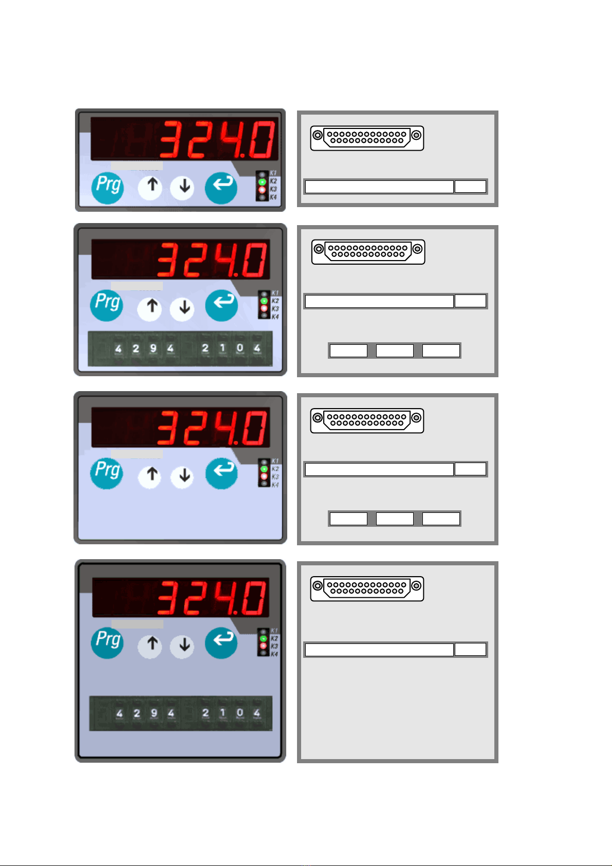
3. Bedienung der Tastatur 3. Keypad operation
Die Tastatur besteht aus 4 Tasten
(Tastatur-Sperre siehe 14)
The keypad uses four keys
(Keypad disable see 14)
Die Programmierung beginnt mit Betä-
tigung der Taste „PRG“. Das Gerät zeigt
nun „P00“ womit der Parameter mit der
Nummer 00 angewählt ist. Mit den Pfeil-
tasten lässt sich die Parameter-Nummer
aufwärts und abwärts rollen. Bei gleich-
zeitiger Betätigung einer Pfeiltaste und der
PRG-Taste rollen die Werte schnell.
To set parameters, touch „PRG“ first. The
unit will display „P00“ which means the
parameter with number 00 is selected now.
Use the arrow keys to scroll the parameter
number up and down. When at the same
time you keep „PRG“ down, the unit scrolls
at high speed.
Wenn der gewünschte Parameter gefunden
ist, Taste „ENT“ betätigen. Auf dem Display
erscheint nun der zum Parameter gehörige
Wert. Auch dieser lässt sich mit den Pfeil-
tasten (ggfs. bei gedrückter PRG-Taste)
langsam bzw. schnell verändern.
When the display shows the desired para-
meter number, press „ENT“ and see the
actual value of the parameter selected. Use
again the arrow keys and, if applicable, the
„ENT“ key to increment or decrement the
value at slow or fast speed.
Ist der richtige Zahlenwert gefunden, „ENT“
betätigen. Das Gerät geht über zur näch-
sten Parameter-Nummer.
Once the desired value has been reached,
press „ENT“. The display will change over to
the next parameter number.
Sobald für eine Zeitdauer von ca. 8 sec
keine Taste mehr betätigt wurde, speichert
das Gerät alle bis dahin geänderten und mit
ENT bestätigten Werte im EEProm ab und
kehrt automatisch zur normalen Istwertan-
zeige zurück.
As soon as no key has been activated for a
period of 8 seconds, the unit stores all new
values which have been confirmed by ENT
and automatically returns to the normal
display mode. All parameters are held on an
EEProm.
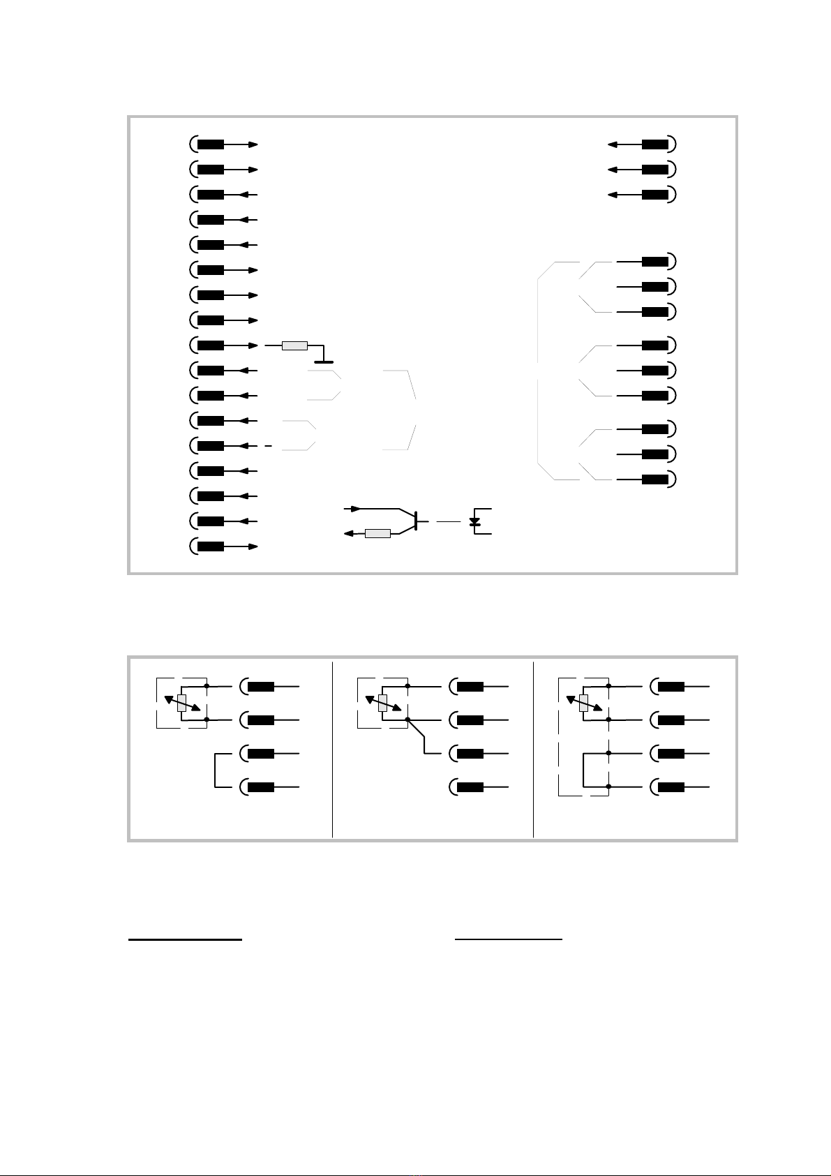
4. Signalanschluss 4. Analogue inputs
Abhängig von Art und Größe des Signals
muss dieses an den entsprechenden Klem-
men zugeführt werden.
( Pt100 siehe Seite 6 )
Depending on the input signal, the corres-
ponding terminals must be used as input
lines.
( For Pt100, see page 6 )
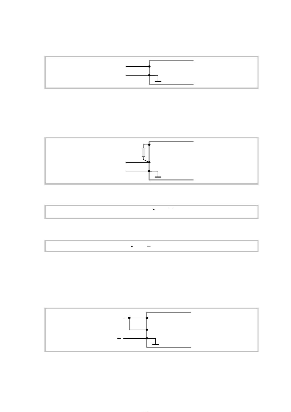
4.1 Bereich 0 - 1 V :
( Ri = 25 KOhm )
4.1 Range 0 - 1 V:
(Ri = 25 KOhm )
X 1 / 6
X 1 / 3
+/- 1 V
0 V GND
AX

9
4.2 Bereich 0 - 10 V:
( Ri = 250 KOhm )
4.2 Range 0 - 10 V
( Ri = 250 KOhm )
X 1 / 7
X 1 / 3
+/- 10 V
0 V GND
AX
4.3 Individueller Spannungsbereich 4.3 Individual Full Scale Range
Um die volle Auflösung des DAC zu nutzen,
kann es manchmal zweckmäßig sein, das
“full scale“ Signal individuell festzulegen.
Dieses kann durch einen externen Wider-
stand Rx erfolgen.
For some applications it may be useful to
have an individual full scale input in order to
have the full resolution of the internal DAC.
This is possible with use of an external
resistor Rx.
X 1 / 8
X 1 / 3
+/- U x
0 V GND
AX
Rx
X 1 / 6
Unter Weglassen der Dimensionen ergibt
sich der benötigte Widerstandswert aus:
Omitting the dimensions, we get the value of
the resistor by
R x = Ux 25 25
( Rx = Kiloohm, Ux = Volt )
Beispiel: Gewünschter Messbereichs-
Endwert = 120 Volt
Example: Desired full scale input
voltage = 120 Volts
R x = KOhm25 25120 = 2975
Aus isolationstechnischen Gründen wird
nicht empfohlen, Spannungen über 120 V
an den Eingangsklemmen anzulegen.
For reasons of isolation we do not
recommend to apply voltages higher than
120 Volts to the input terminals.
4.4 Stromeingang 4.4 Current input
0-20 / 4 - 20 mA
( Ri = 50 Ohm )
0 - 20 / 4 - 20 mA
( Ri = 50 Ohms )
X 1 / 3
20 mA
+
GND
AX
X 1 / 9
X 1 / 6
Die Anwahl 0 - 20 mA oder 4 - 20 mA
erfolgt per Parameter.
Selection 0 - 20 mA or 4 - 20 mA is register
settable.

10
5. Skalierung der Anzeige
5. Scaling procedure
5.1 Setzen Sie zuerst den Parameter P 01
( Betriebsart ) auf den gewünschten
Eingangsbereich bzw. Anzeigemodus.
5.1 Select the desired P 01 input range and
display mode by the mode register P01.
P 01 Bereich Characteristic Bild
Range Characteristics Figure
0 - 1 V
0 - 10 V
0 - 20 mA
4 - 20 mA
proportional
reciprocal
proportional
proportional
proportional
reciprocal
reciprocal
reciprocal
1
2
3
4
5
6
7
8
0 - 1 V
0 - 10 V
0 - 20 mA
4 - 20 mA
Bei eigener Festlegung des Messbereiches
durch externen Widerstand ist der Bereich
0 - 1V zu verwenden. Bei Pt100- Geräten
ist P01 irrelevant.
When you use an external resistor to make
your own range, select the 0 - 1 V mode.
With Pt100 version, P01 setting is not
relevant.
Bei proportionaler Betriebsart ergibt sich
die
Anzeige aus:
With proportional operation modes, the
unit displays
Full scale
Input
( P 01 )
( V, mA )
Display Scaling Factor ( P 02 ) Offset( P 17 )= +x
Bei reziproker Betriebsart ergibt sich die
Anzeige aus:
With reciprocal operation modes the unit
displays
Full scale
Input
( P 01 )
( V, mA )
Display Scaling Factor ( P 02 ) Offset( P 17 )= +x
5.2 Setzen Sie den Skalierunsfaktor P 02 auf
den Zahlenwert, den Sie bei Vollaussteuer-
ung anzeigen wollen
5.2 Set the scaling factor P 02 to the
desired display value at full scale input.

11
5.3 Mit Parameter P 07 können Sie an beliebi-
ger Stelle einen Dezimalpunkt zuschalten.
5.3 Register P07 allows to set a
decimal point at any position
P07 Display
0 xxxxxx
1 xxxxx.x
2 xxxx.xx etc
5.4 Parameter P 30 erlaubt die Zuschaltung
einer fließenden Mittelwertsbildung.
Stellen Sie diesen Wert auf 1 ( keine Mittel-
wertsbildung ) oder auf die gewünschten
Mittelwertszyklen ( max. 16).
5.4 Register P 30 selects the floating average
calculation. Set it to “1“ ( no average ) or to
the number of cycles you like ( max. 16 ).
“Fließend“ bedeutet, dass das Gerät mit je-
dem neuen Messzyklus den Mittelwert der
letzten “n“ Zyklen anzeigt. Ein Messzyklus
dauert 200 msec.
“Floating average“ says, that with every new
measuring cycle the display is updated with
the average of the latest “n“ cycles. One
cycle takes 200 msec.
5.5 Wenn Sie nicht eine eigene
Linearisierungs-kurve vorgeben möchten,
sollten Sie sich vergewissern, dass
Parameter P 16 auf “0“ steht (
Linearisierung aus ).
5.5 You should verify that register P 16 is set to
“0“ ( Linearisation off ), unless you desire
to enter your own linearisation curve.
Die Einstellung des Gerätes ist damit be-
endet. Weitere Einstellungen sind nur
für Zusatzfunktionen notwendig und
werden je nach Bedarf durchgeführt.
At this time, all basic registers are set.
Further settings for supplementary
functions must be made only when
needed.
6. Verschiebung des Nullpunktes
6. Displacement of the zero position
Mit Parameter P 17 ( Normaleinstellung 0 )
können Sie den Nullpunkt positiv oder
negativ verschieben.
Wertebereich - 99 999...0...+ 99 999.
Der hier eingegebene Wert wird vom Gerät
zum normalen Messwert addiert.
Register P 17 ( normal setting 0 ) allows to
set the zero position to any positive or
negative value.
Setting range - 99 999...0...+ 99 999.
Register data is added to the display value.
P17 = + 200
P17 = 00
P17 = - 300
Input ( V )
- 300
200
Display
Bei Pt100- Geräten, die in 2-Leiter- Schal-
tung betrieben werden, dient P17 zum
Leitungsabgleich.
Where Pt100 version are used with 2-wire
connection, P17 serves for compensation of
the line resistance

12
7. Programmierbare Linearisierung
7. Programmable Linearisation
Eine Linearisierung kann über 10 frei wähl-
bare x / y - Koordinaten durchgeführt wer-
den. Das Gerät verbindet die Zwischen-
stücke mit Geraden. Deshalb ist es ratsam,
die meisten Punkte dort zu setzen, wo die
Kurve die größte Krümmung aufweist
You can linearise your display by selecting
10 x / y coordinates within the measuring
range. Between these coordinates, the unit
forms straight lines. Therfore it is
recommen-ded to set most of the
coordinates at the place of maximum
curvature.
Bei Pt100- Geräten ist die Linearisierung
fest hinterlegt und automatisch eingeschal-
tet.
Pt100 versions use a fixed linearisation
which is active at any time.
7.1 Programmieren Sie das Gerät im Normal-
betrieb zunächst so, dass die Messgerade
der gewünschten Kurve am nächsten
kommt. ( P16 = 0, Linearisierung aus ! ).
7.1 Set the unit first up for normal operation in a
way that the straight measuring line comes
next to your curve. ( P16 = 0, Linearisation
off ! ).
7.2 In den Registern P 41 - P 50 werden nun
10 x - Werte eingegeben. Ein x - Wert ist
derjenige Wert, den das Gerät ohne einge-
schaltete Linearisierung bei einer bestimm-
ten Eingangsgröße anzeigt. Als erster Wert
muss unter P 41 der Nullpunkt eingegeben
werden. Als letzter Wert wird der Endwert
des Messbereiches in Register P50 einge-
geben. Zwischen den beiden Endwerten
können in steigender Reihenfolge beliebige
x - Werte vorgegeben werden.
7.2 Use Register P 41 - P 50 to enter 10 x -
values. These are the values the unit dis-
plays in normal operation, while the lineari-
sation is switched off. As a first setting, use
the “zero input“ display and set it to P 41. As
last value, use the “full scale input“ display
and set it to resister P 50. You have another
8 values between P 41 and P50 which can
be set according to need, but a rising
sequence must be guaranted.
7.3 Tragen Sie nun die y - Werte in die
Register P 51 - P60 ein, das sind die Werte,
die Sie später anstelle der zugeordneten x -
Werte ablesen möchten.
7.3 Now enter the y values to register P 51 -
P 60. These are the values you like to see
on the display, instead of the corresponding
x value.
Beispiel:
Wenn Sie unter x - Wert P 42 den Wert
“100“ und unter y - Wert P 52 den Wert
“126“ eintragen, zeigt das Gerät an dieser
Stelle statt 100 die Zahl 126 an usw.
Example:
You have entered the x value “100“ to
register P 42 and the value “126“ to register
P52. This means, the unit later displays
“126“ instead of “100“ with normal operation.
Der Verlauf der y - Werte darf beliebig stei-
gen und fallen.
At any time you can use increasing and
decreasing values for the y - registers.
7.4 Wenn alle x / y - Wertepaare eingegeben
sind, Parameter P 16 auf “1“ setzen. Das
Gerät arbeitet nun mit der vorgegebenen
Linearisierungskurve.
7.4 Once all x / y couples are entered, set
register P 16 to “1“ to switch the lineari-
sation function on.
Beispiel 1: Example 1:
Out
0+
Wegmessung mit einem Linearpotentiometer
Position control with linear potentiometer

13
Linearpotentiometer haben in den
Endberei-chen oft Ungenauigkeiten.
Außerdem ergibt sich eine
Kurvenkrümmung durch die Be-lastung des
Schleifers mit dem Messstrom, was im
Mittelbereich zu Messfehlern führt.
Abhilfe: Messstrecke Stück für Stück ab-
fahren, Anzeige ablesen und Wert in
x - Register eintragen. Von Hand nachmes-
sen und tatsächliches Maß im zugehörigen
y - Register eintragen.
In their externe positions, lineare potentio-
meters mostly are not accurate enough.
Also, by loading the Wiper with a measuring
current, noulinearity comes up especially in
the centre range and the measuring results
are inaccurate.
Solution: Move the potentiometer from one
end to the other, step by step. See the dis-
play and enter this value to an x register.
Check what the real position is and enter
this value to the corresponding y register.
Beispiel 2: Example 2:
Mit Hilfe eines Drucksensors soll die
Füllmenge eines Behälters ermittelt und
angezeigt werden. Das Analogsignal des
Sensors ist proportional zum Füllstand,
aber nicht zum Volumen.
With use of a pressure sensor, the filling
volume of a tank should be displayed.
The sensor output signal is proportional to
the filling level, but not to the volume.
X1 X3
X2 X4
X5
X6
X7
X8
X9
Y 1 (P51)
Y 7
Y 8
Y 9
X 9
X 10 ( P 50 ) Y 10 ( P 60 )
X 1 ( P 41 )
P
Volume
Display
Sensor
X10
Output
Der nicht- lineare Teil des Behälters wird in
acht gleich große Teile X 1 bis X 9 unter-
teilt. Die bei der jeweiligen Füllhöhe
erwarteten Anzeigewerte werden in den
Parametern P 41 bis P 49 gespeichert.
Divide up the non - linear part of the tank to
8 equal sections and set registers P 41 to
P 49 to the appropriate linear readings.
Für den linearen Teil des Behälters wird
dann nur noch der Endwert, also der Mess-
wert bei vollem Behälter benötigt und unter
Parameter P 50 gespeichert.
For the linear part of the tank, only one
output value is necessary ( i. e. the
maximum filling level ) which can be set to
register P 50.
Die bei den jeweiligen Spannungen bzw.
Strömen gewünschte Anzeige ( Füllmenge
) wird nun in den Parametern P 51 bis P 60
abgespeichert.
Now use the registers P 51 - P 60 to specify
the desired readings with the input signals
P 41 - P 50.
Beispiel 3:
Das nachstehende Bild zeigt wie man aus
einer linearen Eingangsgröße eine kreis-
förmige Ausgangsgröße bilden kann.
Example 3:
The subsequent example shows how to
make a circle curve from a linear input
signal.

14
Solche Funktionen sind besonders inter-
essant bei Geräten mit Analogausgang
( Option )
Such functions may especially be interesting
for units with analogue output (option ).
Analogue Analogue
In Out
AX
P42
P43
P44
P45
P46
P57
P59
P60
P47
P48
P49
P50
P52
P53
P54 P55 P56
P58
V, mA
P41
P51
Display,
Analogue Output
Anzeige,
Analogausgang
Eingang
/ Input
8. Eingabe von Grenzwerten 8. Presets and outputs
Unter Parameter P10 kann ein Grenzwert
„Min“ und unter Parameter P11 ein Grenz-
wert „Max“ vorgegeben werden. Die ent-
sprechenden Ausgänge sind aus dem An-
schlussplan ersichtlich. Die Vorgaben erfol-
gen im gleichen Zahlenformat wie die
Istwert-Anzeige.
Register P10 (Min) and P11 (Max) operate
as presets and the corresponding outputs
are assigned in the connection diagramm.
The preset values use the same digit format
as chosen for the display.
Der Parameter P12 definiert das
Schaltverhalten des Min-Ausganges
P12=1: Beide Ausgänge schalten bei
Überschreiten.
Register P12 selects the switching
characteristics of the „Min“ output.
P12=1: Both outputs switch on upon
overpassing the preset value.
P12=2: Ausgang „Min“ schaltet bei
Unterschreiten, Ausgang „Max“ schaltet
bei Überschreiten (Fensterfunktion)
P12=2: Output „Min“ switches on upon
underpassing and output „Max“ switches on
upon overpassing (window function)
P18 - P20: Die Eingabe „0,00 sec.“ bewirkt
eine statische Funktion der Schaltaus-
gänge. Alle anderen Eingaben bewirken
einen Wischimpuls entsprechender Dauer.
P18 - P20: Setting „0.00 sec.“ results in
static operation of the outputs. Any other
setting will generate an output pulse with
corresponding pulse width.
P18 = Ausgang / Output Min (K2)
P19 = Ausgang / Output Max (K3)
P20 = Ausgang / Output Zero (K4)

15
Max
Min
Output "Min"
Output "Max"
Output "Min"
Output "Max"
P12 = 1
P12 = 2
Display
Wenn Ausgang „Min“ als Minimalwertüber-
wachung genutzt wird, kann mit Parameter
P29 eine Anlaufüberbrückung vorgege-
ben werden, damit nach Netzzuschaltung
die Maschine erstmal hochlaufen kann,
bevor der Minimalwert-Ausgang aktiv wird.
Die Anlaufüberbrückung kann im Bereich
von 0.01 sec bis 99.98 sek vorgegeben
werden. Bei Vorgabe 99.99 (Auto) bleibt
der Minimum-Ausgang automatisch
solange gesperrt, bis die Minimumschwelle
zum erstenmal überschritten wurde.
When using the „Min“ output as real
Minimum control, register P29 provides a
start-up delay. This is in order to temporary
supress the alarm while the machine is
starting up after power down.
The delay time can be set between 0.01 sec
and 99.98 sec. Setting to 99.99 provides a
special automatic function and the minimum
output remains disabled until the minimum
level has been overpassed the first time,
independant of the time needed.
9. Minimum- und Maximumspeicher 9. Minimum and Maximum register
Im Register P26 zeichnet das Gerät perma-
nent den minimal aufgetretenen Messwert
auf. Register P27 macht dasselbe mit dem
Maximalwert. Beide Register können nur
ausgelesen, aber nicht beschrieben
werden.
The unit continuously records the minimum
read out value in register P26 and register
P27 does the same with the maximum
value. Both are Read-only registers and
cannot be overwritten.
Beide Register werden wie folgt auf den
momentan angezeigten Messwert zurück-
gesetzt:
Parameter P74 anwählen, auf „1“ setzen
und mit ENT bestätigen.
The register can be cleared to the actual
display value by selecting P74, setting it to
„1“ and pressing ENT.
Damit beginnt, ausgehend vom aktuellen
Messwert, eine neue Aufzeichnung der
Minimal / Maximalwerte.
This will start a new recording period,
proceeding from the actual display value

16
10. Frontseitige Tastenfunktionen
(P23-P25) 10. Additional key functions
(P23-P25)
Neben der normalen Eingabefunktion
können die frontseitigen Tasten ,
und ENT noch für Zusatzfunktionen
herangezogen werden (z.B. frontseitiges
Reset). Die Zuordnung kann vom
Anwender entsprechend der Vorgabe in
P23 bis P25 selbst definiert werden. Wenn
P23-P25 allesamt mit „0“ programmiert
werden, hat keine der frontseitigen Tasten
eine Zusatz-
Beside the normal register setting functions,
it may be desirable to have further functions
attached with a front key (i.e. Reset). This is
possible with the keys , and ENT
which can be set to additional functions by
registers P23-P25. When you set all
registers P23 to P25 to „0“, you will have no
supplementary functions of the front keys.
Tastenfunktion Key operation
Clear Min / Max memoryTaste / Key
P23 = 5
P24 = 5
P25 = 5
( P23 )
( P24 )
ENT ( P 25 )
-
Send ( Serial RS ) *)
P23 = 9
P25 = 9
P24 = 9
*) Nur bei Option serielle Schnittstelle *) With option “serial interface” only
11. Analogausgang (Option) 11. Analogue Output (Option)
Der Analogausgang arbeitet stets pro-
portional zur Anzeige, enthält also auch
eine ggfs. zugeschaltete Mittelwertsbildung
(P30) oder eine dem Vorzeichen
angepasste Polarität (P28).
The analogue output is proportional to the
display at any time, i.e. it also considers
average calculation if selected (P30) and
changes the polarity with the sign (P28).
a.) Wählen Sie das gewünschte Signal-
format mit Parameter P34:
a.) Register P34 selects the signal format
P34 =
P34 = 10V:
:
P34 = : mA
1
2
3
0 - +/-
0 - 20
4 - 20 mA Ω
(Rmax = 270
(Imax = 3mA, resolution +/- 2000 steps)
, resolution 2000 steps)
, resolution 1600 steps)(Rmax = 270Ω
b) Wählen Sie den gewünschten Maximal-
Ausgangspegel mit Parameter P36:
b.) Select the desired output swing by
register P36:
P 36
P 36
P 36
=
=
=
1000
600
150
:
:
:
10,0V
6,0V
1.5V
( 20,0 mA )
( 12,0 mA )
( 3,0 mA ) ect.
c.) Wählen Sie den gewünschten Nullpunkt
mit Parameter P35. Normaleinstellung 0.
Einstellbereich zwischen -2.000 und
+2.000.
c.) Select the desired zero output by
parameter P35. Normally, the setting
should be „0“, but you can adjust
between -2.000 and +2.000.
d.) Geben Sie unter Parameter P33
denjeni-gen Anzeigewert vor, bei dem
Sie Voll-aussteuerung des
Analogausganges wünschen.
Einstellbereich 1 - 999 999
d.) Set register P33 to this display value
which should give you full scale analogue
signal.
Range 1 - 999 999

17
12. Parallel-Ausgang (Option) 12. Parallel Output (optional)
Parameter P32 gestattet die Vorwahl des
gewünschten Ausgabeformates:
Register P32 selects the desired output
code:
P32 = 1
P32 = 2 BCD- Code
Binary Code
:
:
P32 = 3 : Gray Code
Alle 20 Ausgangsleitungen sind opto-isoliert
und PNP-schaltend.
All of the 20 output lines are opto isolated
and provide PNP characteristics.
Com. +
Out 1
Out 2
etc.
Ausgangsschaltung
Output circuit
Der Parallelausgang kann über die
Eingänge “Strobe“ und “Hold“ in seiner
Funktion gesteuert werden.
There are two control inputs attached tothe
parallel output lines, a Strobe and a Hold
input.
Strobe ( Pin 1 ) offen oder “Low“:
BDC- Daten liegen an.
Strobe ( Pin 1 ) open or “Low“
The output transistors are active.
Strobe ( Pin 1 ) “High“ ( 18 - 30V ):
Die Ausgänge sind gesperrt (hoch-ohmig ).
Strobe ( Pin 1 ) “High“ ( 18 - 30V ):
The outputs are in a high impedance state.
Dadurch ist es möglich, die Ausgangs-
leitungen mehrerer Geräte parallel zu
schalten ( Busverdrahtung ) und mit dem
Strobe- Signal jedes einzelne Gerät auf den
Bus zu schalten.
It is possible to wire all ouputs lines of
several units in parallel and to select bus
data by setting one of the strobe lines to
“Low“ whilst all other Strobes are High.
Hold ( Pin 14 ) offen oder “Low“: Die
Daten am Ausgang werden permanent
aufgefrischt.
Hold ( Pin 14 ) open or “Low“:
Output data is updated coutinuously.
Hold ( Pin 14 ) “High“ ( 18 - 30V ): Die
Ausgangsdaten werden eingefroren, bis
Hold wieder auf “Low“ geht.
Hold ( Pin 14 ) “High“ ( 18 - 30V ): Output
data is freezed until the Hold input goes
“Low“ again.
54
17 16
321
15 14
11 10
23 22
98
21 20
76
19 18
1248
MSD
MSD-1 MSD-2 MSD-3
LSD
13 12
25 24
Höchstes Digit / High order digit Kleinstes Digit / Low order digit
1248 1248 1248
1248
Strobe
Hold
Com +
( 5 - 30 V )

18
13. Die serielle Schnittstelle
( Option ) 13. The Serial interface
( Option )
13.1 Konfiguration ( P93 )
Entsprechend der Tabelle kann mit P93
die Konfiguration bestimmmt werden.
13.1 Configuration ( P 93 )
Register P93 selects one of the following
configurations.
P 93 = 1 : *
P 93 = 2 :
P 93 = 3 :
RS 232
RS 485 ( 4 wire )
RS 485 ( 2 wire )
Werkseinstellung Factory setting* =
13.2Baudrate ( P 91 ) 13.2 Baud Rate ( P 91 )
P91
0 *
1
Baud Rate
9600
2
3
4
5
6
4800
2800
1200
600
38 400
19 200
Werkseinstellung Factory setting* =
13.3Datenformat ( P 92 ) 13.3 Data Format ( P 92 )
0 *
1
Data bits
2
3
4
5
6
Werkseinstellung Factory setting* =
Parity
7
8
9
7
7
7
7
7
7
8
8
8
8
even
even
odd
odd
none
none
none
none
odd
even
Stop bits
1
1
1
2
1
1
2
2
2
1
P92
13.4 Geräteadresse ( P 90 ) 13.4 Device address ( P 90 )
Insbesondere bei RS 485- Betrieb ist es
notwendig, den einzelenen Geräten eine
Adresse zuzuordnen, da bis zu 32 Geräte
auf demselben Bus liegen können.
Especially with RS 485 applications it is
necessary to attach a specific address to
each unit, since up to 32 units can be
connected to the same bus.
Den Geräten können Adressen zwi-schen
11 und 99 zugeordnet werden.
Werkseinstellung = 11.
Adressen die eine “0“ enthalten sind nicht
erlaubt, da diese als Gruppen- oder
Sammeladresssen verwendet werden.
You can choose any address number
between 11 and 99.
Factory setting = 11
The address must not contain a “0“
because these numbers are reserved for
collective addressing.

19
13.5 Ausgabeformat ( P 13 ) 13.5 Communication format ( P 13 )
P13 = 1
P13 = 2 PC - Mode
Terminal- Mode ( Protocoll )
( Printer )
:
:
Im PC- Mode müssen die gewünschten
Daten vom PC angefragt werden. Hierzu
wird folgendes Protokoll verwendet:
With PC mode, the PC must send the
following inquiry string:
EOT ..... AD1 AD2 C1 C2 ENQ
AD1 = Unit address, high byte
AD2 = Unit address, low byte
C1 = Register code, high byte
C2 = Register code, low byte
EOT = Control character Ctrl D ( Hex 04 )
ENQ = Control character Ctrl E ( Hex 05 )
Der für den aktuellen Messwert gültige
Register- Code ist :0.
Demzufolge kann bei einem Gerät mit der
Adresse 11 der Istwert mit folgendem
String angefordert werden:
The actual measuring value uses the register
code :0.
For a device with the unit number 11, the
inquiry for the actual value is:
EOT ..... ENQ
11: 0
Das Gerät antwortet darauf The response of the unit will be
STX: 0+/-XXXXXXETXBCC
Control character
Register Code
Meßwert Measuring value
Control character
Block check character
/
BCC
Der Block check character wird gebildet
aus dem Exclusiv- Oder der oben
gekennzeichneten ASCII - Zeichen
The block check character represents the
Exclusive - OR of the characters specified
above.
Der Terminal- Mode wird in der Regel zur
Ansteuerung von Druckern oder zur
automatischen, periodischen Aussendung
des Messwertes benutzt.
Eine Sendung kann ausgelöst werden
über:
The terminal mode allows easy inter-facing
with printers and provides periodical
transmission of the actual measuring value.
There are 3 ways to initialise transmission:

20
−die frontseitige Tastatur
( siehe Abschnitt 10 )
−
by pressing a key on the front
( see section 10 )
−den internen Timer P 14. Dieser ist
einstellbar von 0 sec ( keine auto-
matische Sendung ) bis 500,00 sec
und löst im eingegebenen Zeitintervall
jeweils automatisch folgende Sendung
aus:
−
by using the internal timer register
P 14. You can set the register to 0 to
disable timer transmission, or to any value
up to 500.00 sec to get periodical
transmission of the actual measuring
value to a peripheral device:
11 +/-XXXXXX LF CR
Line Feed
Unit NR.
Carriage Return
Zum Anschluss der seriellen Schnittstelle
steht auf der Rückseite eine 25- polige
Sub- D- Buchse zur Verfügung.
The serial lines are accessible by a 25
position Sub- D- connector ( female ) which
is located on the rear.
13121110987654321
25 24 23 22 21 20 19 18 17 16 15 14
T x D
R x D
GND
Schirm
Screen
Computer
AX
RS 232
13121110987654321
25 24 23 22 21 20 19 18 17 16 15 14
_
+
Computer
AX
RS 485 ( 2 wire )
+_
This manual suits for next models
1
Table of contents
Other ipf electronic Monitor manuals