iplex Pro-fit Manual

PLUMBING, ELECTRICAL AND IRRIGATION 1300 0 IPLEX (1300 0 47539) • CIVIL 13 10 86
The information contained in this document should serve as a guide only and is subject to change
without notice. For more information please contact Iplex Pipelines Australia Pty Ltd.
1
PRO-FIT®POLYBUTYLENE
PLUMBING SYSTEM
TECHNICAL INFORMATION
V1 2019
INSTALLATION
Installation should be carried out in accordance with the guidelines detailed in this manual. However,the installer
should also be aware of Local Authority codes and by-laws relevant to plumbing, which take precedence over these
guidelines in any area where they are at variance. The requirements of the National Plumbing and Drainage Standard
(AS/NZS 3500) must also be adhered to (AS/NZS3500 Parts 2, 4 & 5). The Iplex Pro-fit®system may also be installed
below ground in accordance with AS/NZS 3500 Parts 1 & 4, and Local Authority codes and by-laws.
BEFORE INSTALLATION
1. Store PB pipe under cover where it will not be exposed to direct sunlight.
2. Do not use pipe which has:
• Cuts, deep scratches or gouges.
• Kinks or crushed sections.
• Evidence of grease, oil, tar etc.
• Noticeable colour fading of pipe.
All damaged sections should be cut out and replaced.
JOINTING INSTRUCTIONS - CRIMPED CONNECTIONS
STEP 1
Cut pipe squarely with the Iplex pipe cutter, Iplex Part
No. REMSPIPECUTTER, PBCUTTER or FK203064700.
Do not use a hack saw.
STEP 2
Slide the pipe onto the fitting until it stops. If fitted
correctly, the pipe should be visible through both the
copper crimp sleeve windows (arrowed below). Ensure
that the copper crimp sleeve is firmly attached to the
plastic retainer ring. If the copper crimp sleeve has
moved away from the plastic retainer ring, push it back
onto the plastic retainer ring by hand before crimping.
V1 2019

PLUMBING, ELECTRICAL AND IRRIGATION 1300 0 IPLEX (1300 0 47539) • CIVIL 13 10 86
The information contained in this document should serve as a guide only and is subject to change
without notice. For more information please contact Iplex Pipelines Australia Pty Ltd.
2
PRO-FIT®POLYBUTYLENE
PLUMBING SYSTEM
TECHNICAL INFORMATION
V1 2019
STEP 3
Open crimp jaws all the way apart. Position crimp jaws
squarely over the copper crimp sleeve. i.e at 90° to the
pipeline. For hand tools ensure that the full jaw width
of the tool makes contact with the copper crimp sleeve
when crimping. For power tools crimp the jaws over the
full width of the copper crimp sleeve. Avoid crimping the
plastic retainer ring. Close the crimp tool jaws fully over
the copper crimp sleeve. Open the crimp tool jaws and
remove the crimp tool from the crimped fitting.
STEP 4
Use the Iplex caliper gauge supplied with the tool
to check each and every joint. Gauge tips must fit
over the crimped copper sleeve at 90° to the tool jaw
split line. Permanently tight connections can only be
guaranteed with Iplex approved tools. The tools have
to be protected against dirt and damage, and should
be cleaned regularly.
INSTALLATION
JOINTING INSTRUCTIONS - UNDER-CRIMPING
Under-crimping (i.e. when the gauge will not pass over copper ring) can occur when:
1. The crimping tool has not been completely closed.
2. The crimping tool is out of adjustment (readjustment should be made in accordance with the instructions supplied
with the tool).
HOW TO AVOID A FAULTY CONNECTION
The Iplex Pro-fit®pipes and fittings system is simple and eective to use when executed in accordance with the jointing
procedures. However, if sucient care is not taken, the consequences can be improper sealing, and a potential for leaks.
The most likely causes of faulty connections are:
1. Copper crimp sleeve has moved away from the body of the fitting.
2. The crimping tool has not been centred over the copper crimp sleeve, and thus the sleeve has only
been partially crimped.
3. The pipe has not been pushed fully home on to the fitting when the crimp was made.
4. Pipe has not been cut squarely.
5. Tools are poorly maintained or damaged.
IF AN INCORRECT JOINT IS DETECTED
• Cut out the defective joint and replace with new Iplex Pro-fit®fitting.

PLUMBING, ELECTRICAL AND IRRIGATION 1300 0 IPLEX (1300 0 47539) • CIVIL 13 10 86
The information contained in this document should serve as a guide only and is subject to change
without notice. For more information please contact Iplex Pipelines Australia Pty Ltd.
3
PRO-FIT®POLYBUTYLENE
PLUMBING SYSTEM
TECHNICAL INFORMATION
V1 2019
OD x 10
RIGHT
IF THE PIPE IS KINKED OR DAMAGED
The faulty section of the pipe should be replaced.
IPLEX PRO-FIT®PB PIPE TO COPPER PIPE, STEEL PIPE SYSTEMS OR APPLIANCES
Threaded fittings – brass or copper threaded fittings should not be used with other non-metallic threaded fittings.
Use an approved sealant to seal all threaded fittings.
• When using brazing tails to connect copper pipe or metal fittings to Iplex Pro-fit®PB pipe, always braze the brazing tail
to the copper pipe or metal fittings first and allow it to cool before assembling the Iplex Pro-fit®PB pipe.
At least four ribs should be shown on the brazing tails to allow for an eective joint to be made. It is recommended that
silver brazing alloys be used and that all flux deposits are removed once the joint has been made. Excessive heat can
damage Iplex Pro-fit®PB pipes. When brazing copper pipes or fittings near Iplex Pro-fit®PB pipes it is recommended a
damp rag be used to protect the pipes.
TABLE 1.1 MINIMUM BENDING RADIUS
18mm Pipe 180mm min. radius
22mm pipe 220mm min. radius
Fig 1.1 Minimum bending radius
INSTALLATION
PIPE BENDING
Due to the pipe’s inherent flexibility and its availability
in 50m coils for 18mm and 22mm pipe, polybutylene
can be bent easily around obstructions or through
studs and plates with minimum use of fittings. Care
should be taken not to kink or damage the pipe. It is
recommended that the minimum bending radius be
10 times the outside diameter of the pipe. If this is not
possible an Iplex Pro-fit®elbow should be used. If for
any reason the pipe is kinked or damaged, the faulty
section should be replaced.

PLUMBING, ELECTRICAL AND IRRIGATION 1300 0 IPLEX (1300 0 47539) • CIVIL 13 10 86
The information contained in this document should serve as a guide only and is subject to change
without notice. For more information please contact Iplex Pipelines Australia Pty Ltd.
4
PRO-FIT®POLYBUTYLENE
PLUMBING SYSTEM
TECHNICAL INFORMATION
V1 2019
Expansion control valve
In line non-return valve
Isolating valve
C
old water
supply line
Line strainer
Pressure limiting valve
Easing gear
Expansion control valve
In line non-return valve
Isolating valve
Cold water
supply line
Line strainer
HOT WATER INSTALLATION
1. It is recommended that the Iplex Pro-fit®system be installed in accordance with the manufacturers installation
requirements, AS/NZS 3500 Part 4 and any local by-laws with particular reference to the pressure and temperature
relationship as described in AS / NZS 2642 and detailed in Table 1.2.
TABLE 1.2 PRESSURE RATING OF PIPES ACCORDING TO PIPE MATERIAL TEMPERATURE (AS/NZS 2642)
Working
temp 20°C 40°C 50°C 60°C 70°C 80°C
(25 YEARS)
95°C
(10 YEARS)
Max working
pressure
1600
kPa
1370
kPa
1200
kPa
1050
kPa
880
kPa
740
kPa
490
kPa
2. The valves used in the installation of water heaters should comply with the requirements as laid out in AS/NZS
3500 Part 4, Tables 1.1 & 1.2.
The required set pressure of valves i.e. expansion control valves and inlet pressure control valves shall be:-
a. as specified by the water heater manufacturer; or
b. determined from the set pressure of the temperature and pressure relief valve supplied by the water heater
manufacturer, with reference to AS/NZS 3500 Part 4, Table 1.2.
3. The use of tempering valves is required in some capital cities and provincial areas. Check with your Local Authority.
Fig 1.2 Typical installation mains
pressure storage water heater
with expansion control valve
Fig 1.3 Typical installation of mains
pressure storage water heater
expansion control valve and
pressure limiting valve
INSTALLATION

PLUMBING, ELECTRICAL AND IRRIGATION 1300 0 IPLEX (1300 0 47539) • CIVIL 13 10 86
The information contained in this document should serve as a guide only and is subject to change
without notice. For more information please contact Iplex Pipelines Australia Pty Ltd.
5
PRO-FIT®POLYBUTYLENE
PLUMBING SYSTEM
TECHNICAL INFORMATION
V1 2019
INSTALLATION
4. The water heater thermostat must be set to supply hot water at temperatures less than 80°C.
PLEASE NOTE:
In accordance with AS/NZS 3500 Parts 1 & 4, copper pipe should be used within one metre of the outlet of a hot
water heater. Before connecting PB to instantaneous gas hot water systems, check with the hot water heater
manufacturer for any specific additional requirements. PB should not be used in continuously circulating
hot water plumbing loops operating above 60°C.
CONCEALED PIPE WORK
All concealed pipe work should be installed in accordance with AS/NZS 3500 Parts 1 & 4 or Local Authority
requirements.
TIMBER FRAMEWORK
Holes drilled in studs or plates etc. shall be accurately sized to allow longitudinal movement of the pipe through
the hole with a minimum clearance of 2mm on the pipe’s diameter. A 25mm splade bit is suitable for both sizes of
pipe. Please note that the use of silicon in the holes is not required.
METAL FRAMEWORK
Holes drilled in metal studs or plates etc shall be accurately sized to enable suitable grommets, lagging or a short
sleeve of oversized pipe to be firmly secured in the framework. This is to allow free movement of the pipe through
the grommet, lagging or sleeve without any direct contacts between the pipe and the framework.
THERMAL EXPANSION
As the lineal thermal expansion rate of PB pipe is approximately 13mm for every 10°C temperature change for
each 10 metres of pipe, care must be taken with the installation to allow for this potential movement of the pipe.
PB pipe should not be pulled tight between fixed points as this will prohibit movement if the pipe contracts, and
result in excessive tensile forces on joints and fittings. Allow 10mm slack per metre of pipe. Expansion can usually
be accommodated by the pipe’s flexibility.
Fig 1.4 Indicates
fixed point
Allow 10mm slack per metre of PB pipe
for thermal movement
Elbow
Sleeve
Clip
Elbow

PLUMBING, ELECTRICAL AND IRRIGATION 1300 0 IPLEX (1300 0 47539) • CIVIL 13 10 86
The information contained in this document should serve as a guide only and is subject to change
without notice. For more information please contact Iplex Pipelines Australia Pty Ltd.
6
PRO-FIT®POLYBUTYLENE
PLUMBING SYSTEM
TECHNICAL INFORMATION
V1 2019
CHASES, DUCTS OR CONDUITS
As per AS/NZS 3500 Parts 1 & 4 or Local Authority requirements. Pipes in chases shall be continuously wrapped with
an impermeable flexible material. Ducts shall be fitted with removable covers. Pipes embedded in walls or floors shall
comply with the requirements of the appropriate building authority and/or local regulations.
UNDER CONCRETE SLABS
PB pipe may be installed under concrete slabs in accordance with AS/NZS 3500 Parts 1 & 4, or Local Authority
requirements. When PB penetrates the slab it shall be at right angles to the surface of the slab and shall be lagged
with an impermeable, flexible plastics material of not less than 6mm thickness for the full depth of the slab penetration
ie PVC conduit or pressure pipe.
CLIPPING AND SUPPORTS
The use of pipe clips should be in accordance with AS/NZS 3500 Parts 1 & 4 and in keeping with good plumbing
practice. The following table is based on AS/NZS 3500.
CORROSIVE ENVIRONMENT
As per the requirements of AS/NZS 3500 and/or Local Authority or Regulatory requirements, PB pipe and fittings
installed in potentially corrosive environment must be protected, i.e. marine environment.
TABLE 1.3 THE USE OF PIPE CLIPS
Nom. pipe diameter Horizontal or graded pipes Vertical pipes
18mm 600mm 1200mm
22mm 700mm 1400mm
Fig 1.5 Pipe clipping
Clips on fittings should only be required where the
fittings are obviously stressed. NOTE – the Iplex
Pro-fit®system’s major fixing benefit is that it is
flexible and when installed has the ability to move
and flex. The installation of pipe clips, brackets etc.
is only to give the pipe support and an acceptable
appearance. The pipe clip must not constrain
the pipe diameter and should allow longitudinal
movement of the pipe. We recommend you use the
Iplex Pipelines range of clips.
INSTALLATION
Clip
Clip
Clip
Sleeves
Insulators
Cross Brace
Out of Slab
or Floor
Along wall
stud
Protect Stress
Point

PLUMBING, ELECTRICAL AND IRRIGATION 1300 0 IPLEX (1300 0 47539) • CIVIL 13 10 86
The information contained in this document should serve as a guide only and is subject to change
without notice. For more information please contact Iplex Pipelines Australia Pty Ltd.
7
PRO-FIT®POLYBUTYLENE
PLUMBING SYSTEM
TECHNICAL INFORMATION
V1 2019
Tempering Valve
Hot water
Tempered wa
ter
Line Strainer
& Check Valve
LEGEND: H-Hot
C-Cold
M-Mix
Cold
supply
C
H
M
Solar
Panel
SOLAR HOT WATER
As solar hot water systems are an uncontrolled heat source, temperatures in excess of 75°C are frequently experienced.
To ensure that the supply temperature is maintained well within the normal operating temperatures of polybutylene
pipe it is recommended that the following typical installation procedure be adopted.
1) In addition to the normal valves required for the system, an adjustable tempering valve (e.g. RMC Heatguard Solar
HP or HF or similar) should be installed directly at the solar water heater as per the following diagram.
2) As per AS/NZS 3500 Part 4.2, one metre (1mtr) of copper pipe is then required before connecting to polybutylene
pipe. The copper pipe can be used to penetrate the roof into the roof cavity.
3) The tempering valve can then be adjusted to its maximum temperature (up to 65°C depending on model) by
following the manufacturer’s instructions. This is typically done by removing the adjusting knob locking device and
resetting the temperature.
4) Individual tempering valves are then fitted as required to control water supply temperature to the wet areas in
accordance with AS/NZS 3500 Part 4.2.
THERMOSYPHON SOLAR HOT WATER
INSTALLATION

PLUMBING, ELECTRICAL AND IRRIGATION 1300 0 IPLEX (1300 0 47539) • CIVIL 13 10 86
The information contained in this document should serve as a guide only and is subject to change
without notice. For more information please contact Iplex Pipelines Australia Pty Ltd.
8
PRO-FIT®POLYBUTYLENE
PLUMBING SYSTEM
TECHNICAL INFORMATION
V1 2019
TESTING & INSPECTION PROCEDURES
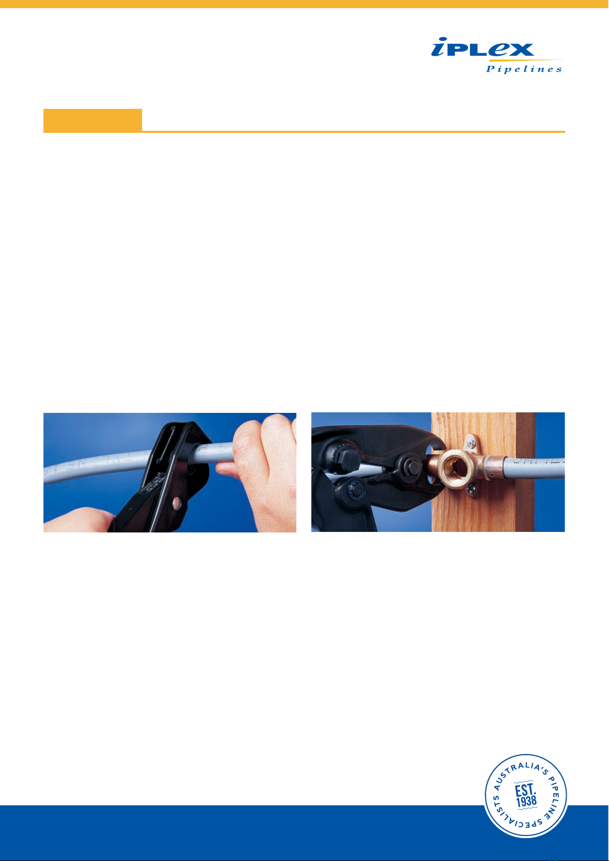
Testing procedures should be as per the requirements of AS/NZS 3500 part 1,4 & 5 and/or any Local Authority or
Regulatory requirements. While the system is under test, all joints and fittings should be inspected for leaks and to
ensure that the pipe has been fitted correctly and crimped in accordance with Iplex Pro-fit®Polybutylene
Plumbing System Installation Guidelines.
FIRE & EXCESSIVE HEAT
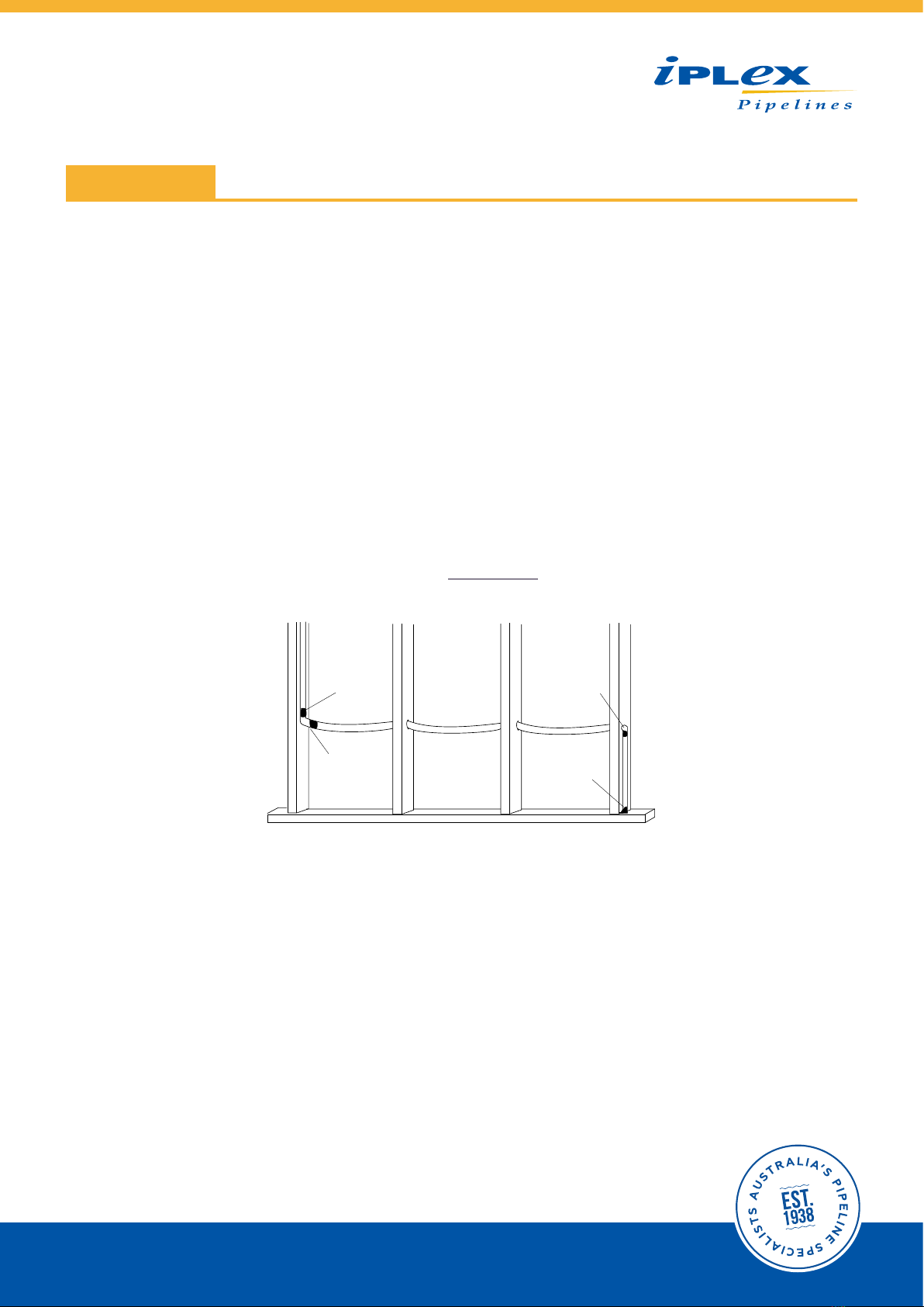
Keep PB pipe a minimum of 500mm from sources of high heat such as heating appliances, flues, vents etc.
Keep PB pipe 1500mm from slow combustion type stoves, vents and flues used to heat domestic hot
water, wet back boilers etc.
PB pipe should not be positioned closer than 150mm to gas or central heating vents, nor located in any confined space
containing appliance vents or flues.
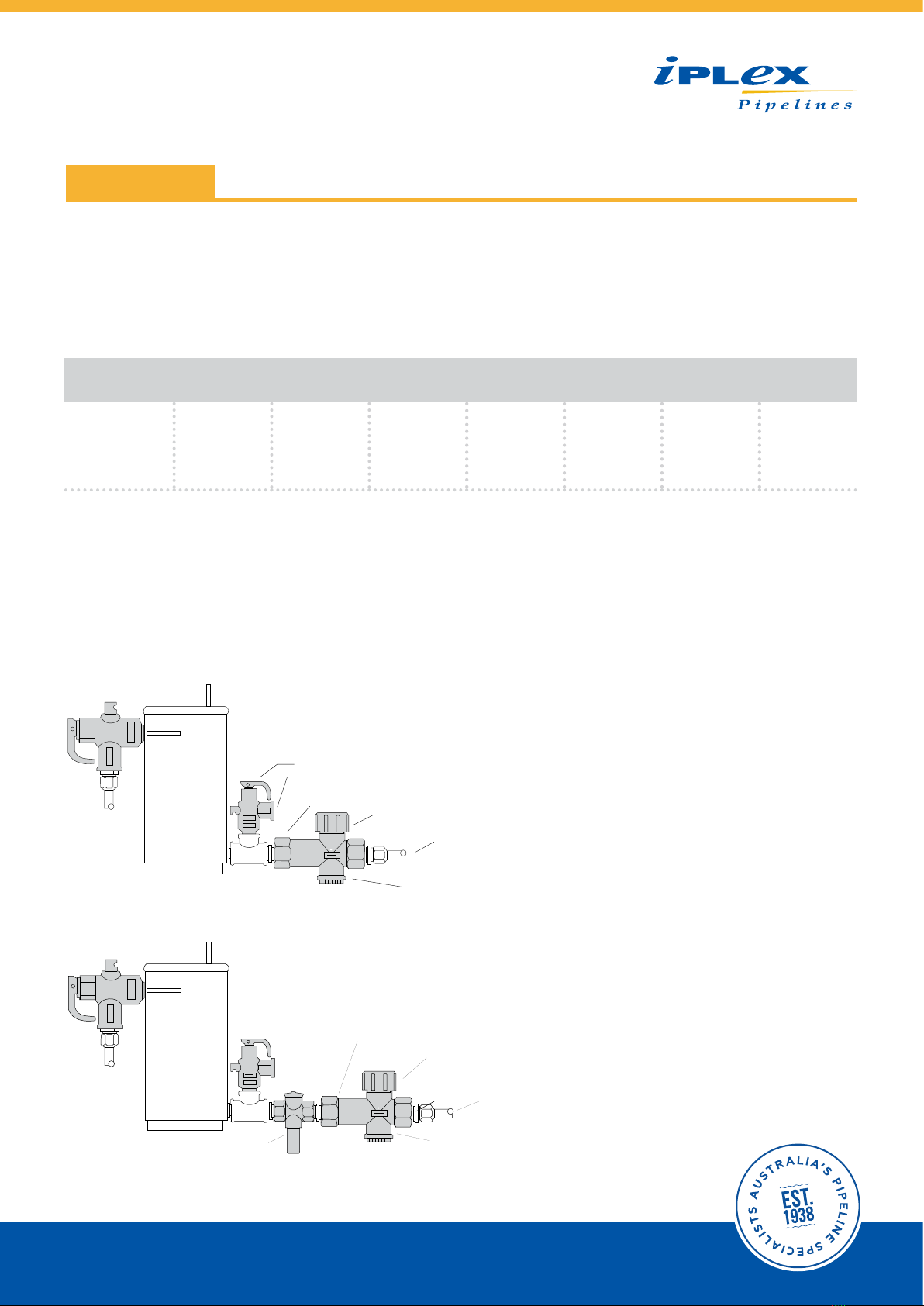
PB pipe and fittings are designed to meet the normal operating temperatures of domestic hot and cold water, however,
in the case of uncontrolled heat input such as slow combustion stoves or room heaters with water heating coils, wet
back boilers or the like, and in the interest of safe water temperature to protect the user, tempering valves must be
considered. The primary flow and returns on these type of appliances should not be installed in PB pipe and fittings.
Where PB pipe is installed and penetrates fire resistant construction, the fire resistant integrity of the construction
must be retained. Refer to the local building code.
PROTECTION
If a system is to be exposed to sunlight beyond normal construction periods, the pipe should be protected from
sunlight (UV) damage. Lineal thermal expansion rate for PB pipe is approximately 13mm/10°C temperature change for
each 10 metres of pipe. Leave 300mm minimum space between PB pipe and recessed electric light fittings, as light
fittings are normally changed on a regular basis.
LIMITATIONS OF PB PIPE
When:
• Used as part of a water meter assembly or vertical riser.
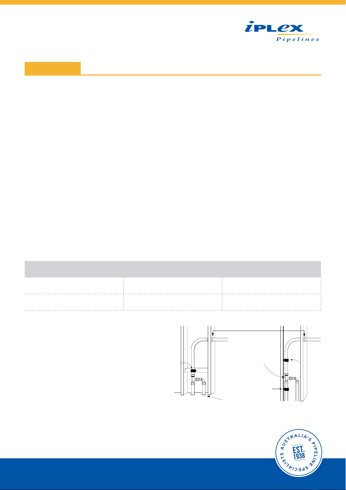
• Used beyond the inlet stop valve to any water heater.
• Used where subject to direct sunlight.
• Used in areas subject to contamination by petroleum products.
• Used within one metre of the outlet of, or between isolation valve and inlet of any water heater.
• Water temperature / pressure combinations should not exceed the limitations as given in Table 1.2.
• Used on continuously circulating hot water loops operating above 60°C.
• Buried underground and subject to flooding with a termite treatment.
INSTALLATION
Table of contents
Popular Plumbing Product manuals by other brands

Invacare
Invacare IH6300ADH Owner's operator and maintenance manual

The Splash Lab
The Splash Lab TSL.960 Series Installation & maintenance

Globo
Globo FO001 Assembly instructions

KWC
KWC Interlaken S.10.D8.02 Specification sheet

BELLOSTA
BELLOSTA revivre 8031/3/A/LB quick start guide

DURAVIT
DURAVIT C14210 0110 10 Instructions for mounting and use

Kohler
Kohler K-10282 Installation and care guide

Haws
Haws H1011.8HPSHO-1920HPSHO quick start guide

Sloan
Sloan Optima EBF-425 Troubleshooting instructions

Hans Grohe
Hans Grohe Axor Starck Organic 12010000 Instructions for use/assembly instructions

Moen
Moen Brushed Bronze 103470BB Replacement parts

Hans Grohe
Hans Grohe AXOR Uno2 38815000 Instructions for use/assembly instructions