TABLE OF CONTENTS
489287.DOC Page 2
SECTION 1: OVERVIEW............................................................................................................................. 3
Product Description....................................................................................................................... 3
Product Functionality .................................................................................................................... 3
External Features ........................................................................................................................... 4
SECTION 2: INSTALLATION INSTRUCTIONS ......................................................................................... 6
Base Station Setup ........................................................................................................................ 6
Rack Mounting Unit............................................................................................................. 6
Installation Overview ..................................................................................................................... 7
Installation Instructions................................................................................................................. 8
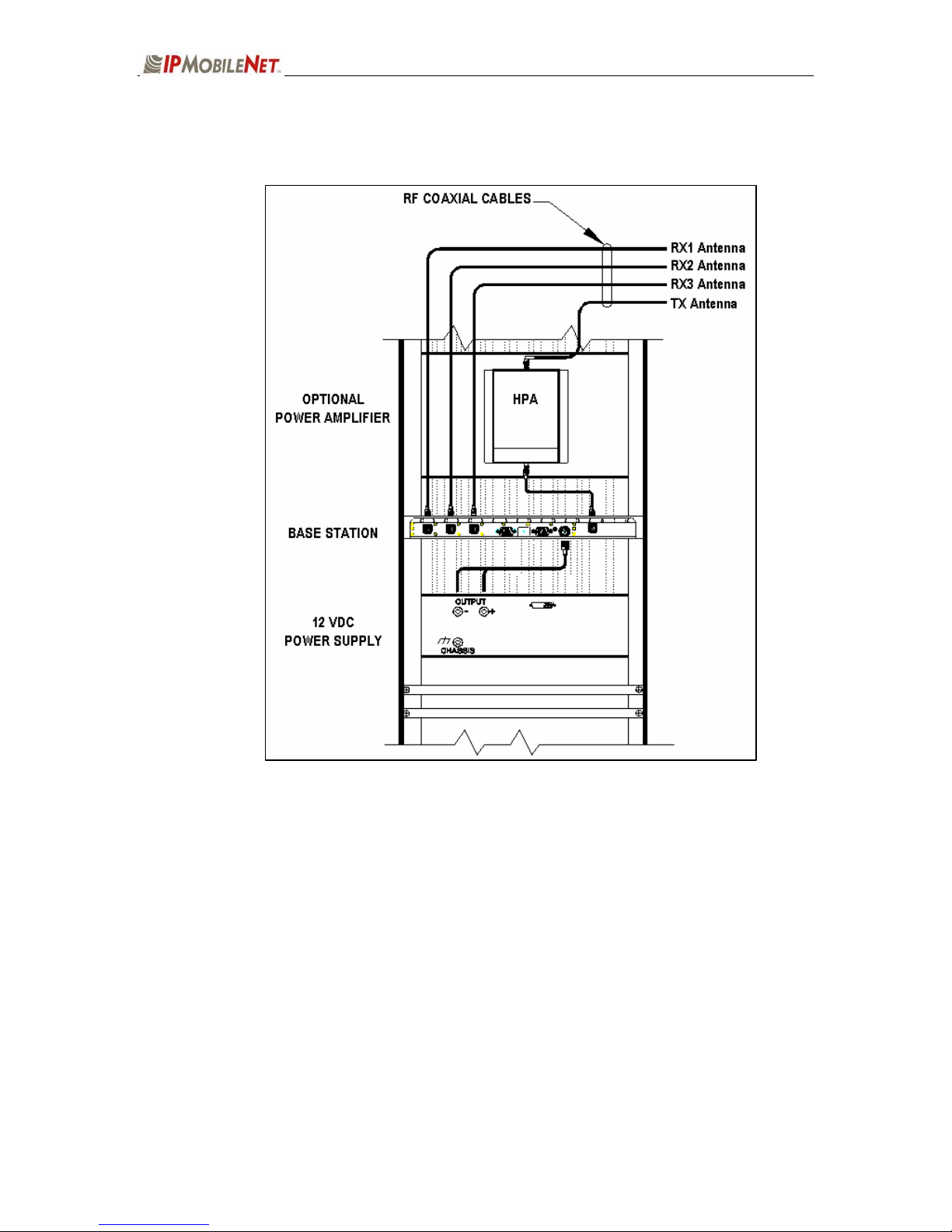
Interconnection Diagram..................................................................................................... 8
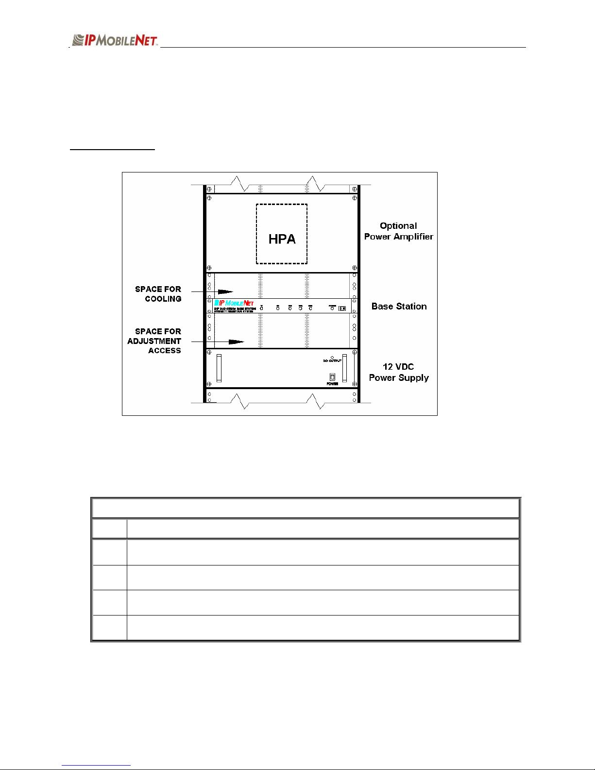
Base Station Installation into Rack Unit.............................................................................. 8
Single Base Station Configuration .................................................................................... 10
Multiple Base Station Configurations................................................................................ 10
Typical Antenna Configuration.......................................................................................... 11
Near-Field Exclusion Zone................................................................................... 12
Power Connection............................................................................................................. 13
Post Installation Checklist ................................................................................................. 14
SECTION 3: PROGRAMMING INSTRUCTIONS...................................................................................... 15
Overview ....................................................................................................................................... 15
HyperTerminal Setup................................................................................................................... 15
Additional Programming Needs ................................................................................................. 17
SECTION 4: FACTORY TEST PROCEDURE .......................................................................................... 18
Equipment List ............................................................................................................................. 18
Programming and Configuring the Base Station ..................................................................... 19
Adjustment / Alignment Procedure............................................................................................ 20
Startup
............................................................................................................................. 20
Receiver Injection.............................................................................................................. 20
Receiver............................................................................................................................ 20
Diversity Reception ........................................................................................................... 21
ReceiveData
..................................................................................................................... 22
Exciter............................................................................................................................. 23
Power Amplifier ................................................................................................................. 23
SECTION 5: FCC LABEL.......................................................................................................................... 24
700 MHZ Base Station FCC Label Placement ........................................................................... 24
700 MHZ Base Station FCC Label............................................................................................... 24
SECTION 6: 700 MHZ TEST DATA SHEET.............................................................................................. 25