iPort CONNECT PRO 72350 User manual

CONNECT
PRO
WALLSTATION
1
72350 - CONNECT PRO WallStation Black
72351 - CONNECT PRO WallStation White

CONNECT
PRO
WALLSTATION
2
IPORT CONNECT Pro WallStation Install
Manual
Whats in box:
1 - IPORT CONNECT WallStation
1 - IPORT Security tool - 1.5mm hex key
1 - Info Card
4- Drwyall Anchors
4 -#6 HighLow thread Screws
1 - RJ45 - DC Connector
1 - RJ45 - TE Connector
1 - Phoenix - DC Connector
1 - Phoenix - TE Connector
Glossary of Terms:
• WallStation - The fully assembled CONNECT PRO
Station holding and charging the IPORT CONNECT
Case.
• Cover Plate - The removeable plastic cover that
attaches to the WallStation, covering the label and
Screws.
• IPORT Security Tool - The orange handled 1.5mm hex
tool used for locking and unlocking IPORT
Products.
Product Info Page - www.iportproducts.com/cpwallsta-
tion
Thank you for purchasing the all new IPORT
CONNECT Platform. We hope you enjoy this revo-
lutionary new system and if at any time you need
more assistance please Contact IPORT Tech Sup-
port via Online chart or through our help desk.
- IPORT Team

CONNECT
PRO
WALLSTATION
3
Before starting, detimine the install scenario
that best describes your desired install. Then
click on the title to be directed to the
appropriate install steps.
New Construction using Cat 6 Cable | pg. 4
Existing Construction using Cat 6 Cable | pg. 15
Upgrading a LAUNCH WallStation | pg. 25
New Construction using 14-2 Wire | pg. 32
Existing Construction using 14-2 Wire | pg. 45
WALLSTATION INSTALL OPTIONS

CONNECT
PRO
WALLSTATION
4
1. Determine the desired location of the
IPORT Connect Pro WallStation will
live when the construction is
completed.
IPORT CONNECT Pro WallStation Install
New Construction - Cat6
Before Construction is complete
CONNECT
PRO
WALLSTATION
5
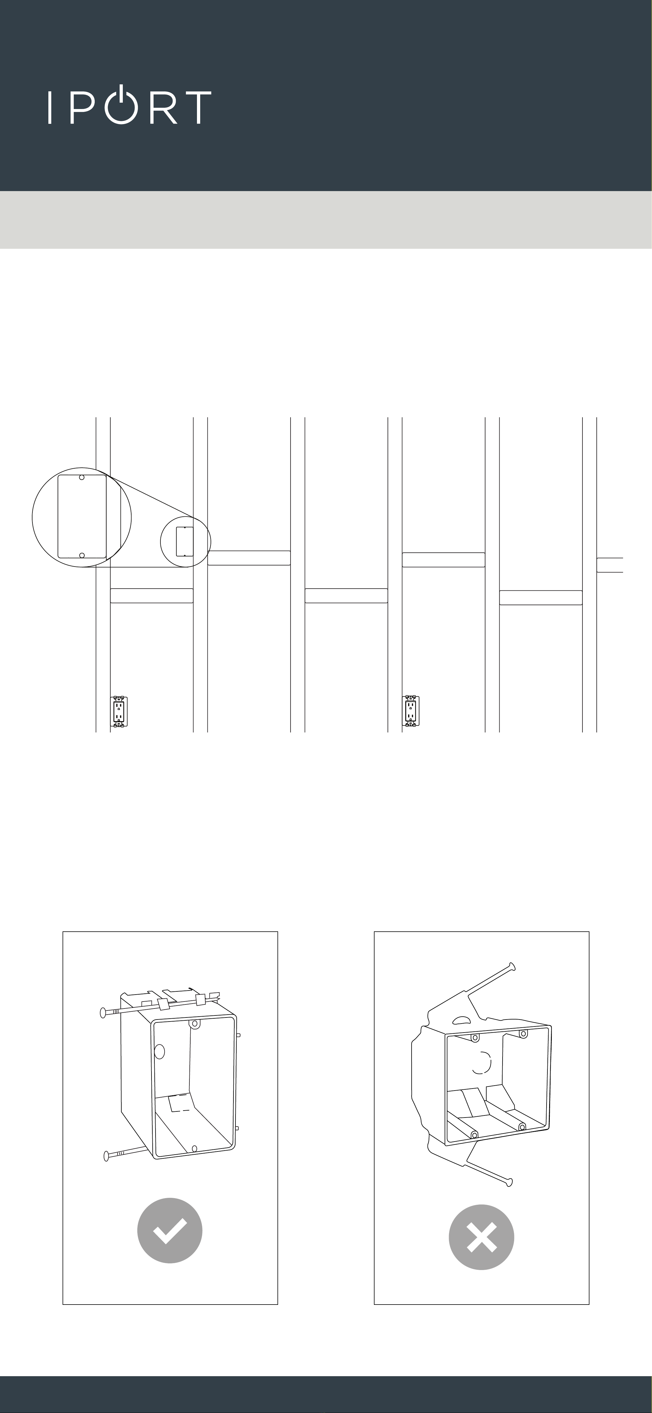
2. Install a 1 Gang electrical box or low
voltage ring in the desired location
of the WallStation.
NOTE: The CONNECT PRO WallStation will cover
a 1G electrical box only. A 2 Gang electrical box will
interfere with the mounting hardware.
1G
Electrical
Box
New Constructions Cat6

CONNECT
PRO
WALLSTATION
6
3. Run a Cat6 cable terminated with an
RJ45 Connectors (T568A or T568B)
from the WallStation location to a
nearbyAC outlet, closet, or network
rack location and terminate the
other endof the cable the same as
before.
NOTE: Make sure to secure the Cat6 cable
appropriately onto the Electrical box or Low
Voltage ring to retrieve at a later time.
New Constructions Cat6

CONNECT
PRO
WALLSTATION
7
Installing the WallStation After
Construction
1. Terminate the Cat6 with an RJ45
Connector if not done so previously
using T568A or T568B standards.
2. Remove the WallSation, Drywall
anchors and Screws from the box
and place on a table.
x4
x4
New Constructions Cat6
CONNECT
PRO
WALLSTATION
8
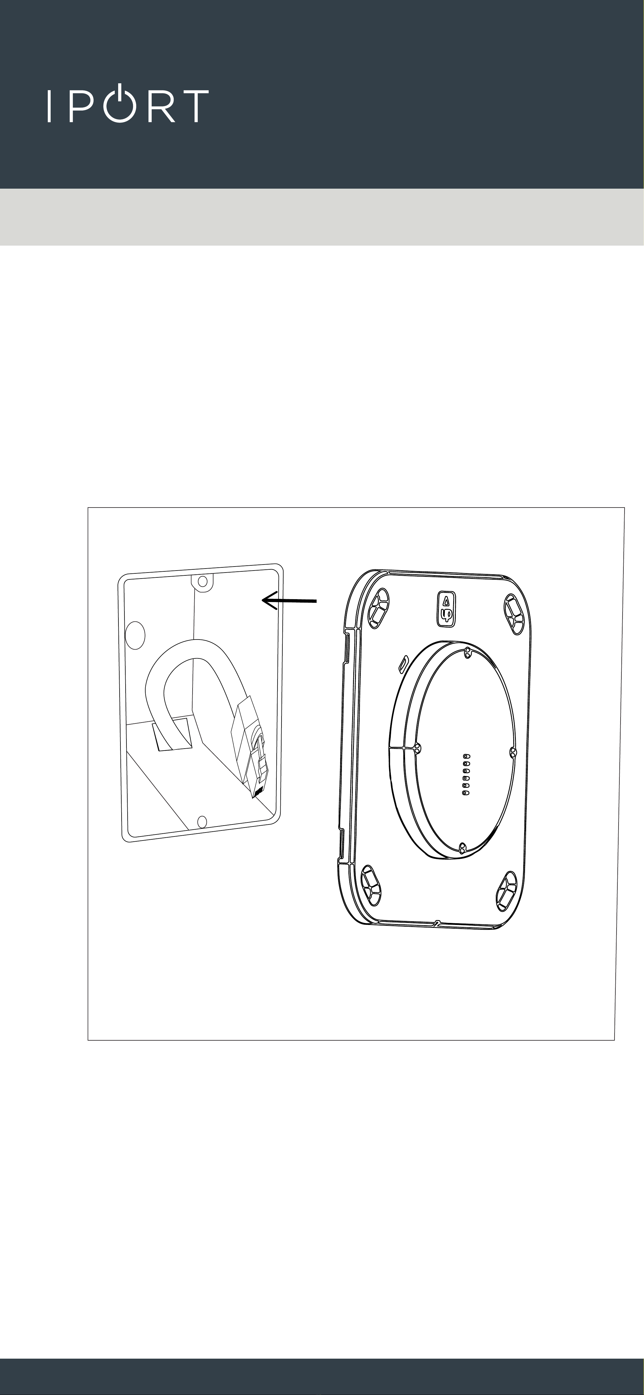
3. Insert the WallStation into the 1G
box.
New Constructions Cat6

CONNECT
PRO
WALLSTATION
9
4. Use a leveling tool to level the
WallStation and mark the 4 locations
for the provided Anchors. Remove the
WallStation from the 1G Box.
5. Screw the 4 provided anchors into
the wall where marked.
New Constructions Cat6
CONNECT
PRO
WALLSTATION
10
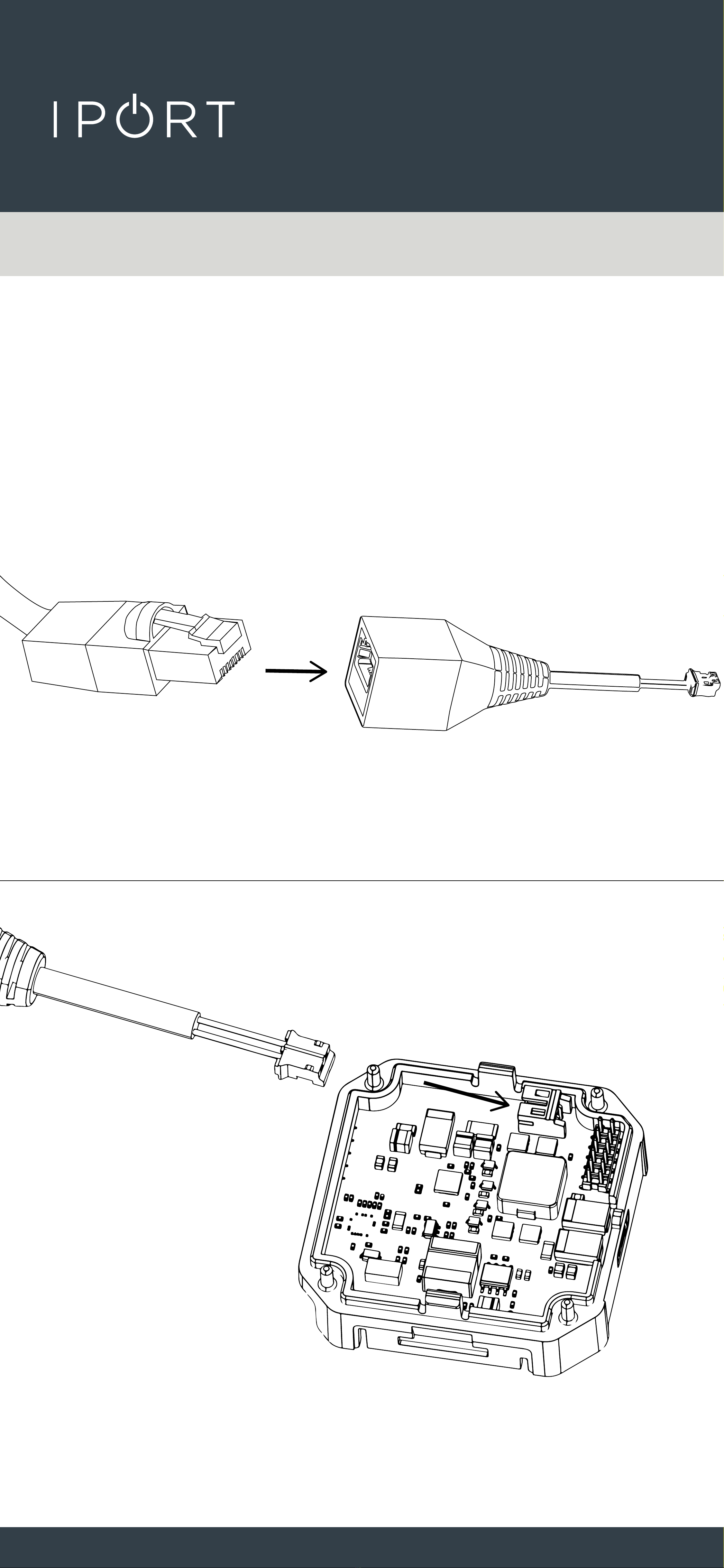
6. Connect the RJ-45 to TE Connector
provided to the Cat6 cable and onto
the white TE connector WallStation
DC Adapter.
New Constructions Cat6
Zip tie the Connector to the DC board for
added cable retnetion.
Label wire WARNING: Only for DC Low
Voltage - Not for PoE
This manual suits for next models
1
Popular Network Hardware manuals by other brands

Matrix Switch Corporation
Matrix Switch Corporation MSC-HD161DEL product manual

B&B Electronics
B&B Electronics ZXT9-IO-222R2 product manual

Yudor
Yudor YDS-16 user manual

D-Link
D-Link ShareCenter DNS-320L datasheet

Samsung
Samsung ES1642dc Hardware user manual

Honeywell Home
Honeywell Home LTEM-PV Installation and setup guide


