IPOX MC201GE User manual

It is gigabit Ethernet fiber optic transmission equipment which can converter between two different network
cables and optical fiber transmission medium. Supporting 10/100/1000 Mbps network bandwidth, this
product can be used in pairs and also can be used with other equipments. It is widely used in surveillance,
home network fiber, etc.
Feature
Provide 1000Mbps 1 fiber optic port and 1 Ethernet port which can converter between
10 /100 /1000BASE-TX and 1000BASE-FX;
Use SFP optical module, support hot plug and SFP optical module with different performances ;
Compatibility with IEEE 802.3, IEEE 802.3u, IEEE802.3ab/z, and Ethernet standard of
10/100/1000BASE-TX and 1000BASE-FX;
Support 10/100/1000Mbps full/half duplex automatic adaptation and automatic MDI/MDIX.
Gigabit Ethernet Converter
12
Gigabit Ethernet Converter
Caution
1) Please attention that 2 optical fibers need to be across connected with Fiber Port of two Gigabit
Ethernet Converters;
2) SFP module need to purchase additionally.
3) The equipment requires lightening protection, otherwise its protection level will be greatly reduced.
please use 20th or over wire to connect ground port to the ground ,
Application
Ethernet Switch
Gigabit Ethernet
Converter
Ethernet Switch
Gigabit Ethernet
Converter
Optical Fiber
Optical Fiber
Power Input
Grounding
Terminal
Pow er
SD
FED
Lin k
SD
FED
Lin k
Fibe r
Ethernet Port Power&Fiber LED
Indicator
Fiber Port
Board Diagram
Rightside Leftside
LED
Function
Status
Instruction
Power
Power LED Indicator
On
Power On
Off
Power Off
FED
SFP Detection Indicator
On
SFP Insert
Off
Without SFP Insert
SD
Remote Device Failure
Detection Indicator
On
Remote Device Failed
Off
Remote Device Communication Normal
Link
Optical Fiber port Connection
Status
On
Connection Normal
Flicker
Connection Normal And With Data Switch
Off
Connection Falied
RJ 45
Indicator
(Link/Act)
Ethernet Port Connection
On
Ethernet Port Connection Normal
Flicker
Connection Normal and With Data Switch
Off
No Connection
LED Indicator Instruction:
Please check the following items before installation. If any missing, please contact the dealer.
Power Adapter
Gigabit Ethernet Converter 1pc
1pc
Hanger 2 pcs
1pc
User Manual
Installation
Installation Steps
1) Please turn off the signal source and device power before installation; Installation with power on may
damage the device;
2) Please check if the network cables being taken up by other devices;
3) Use network cable to connect RJ45 Port of the Converter with NVR or network devices like
computer;
4) Use two single mode optical fibers tor connect two fiber ports of two Fast Ethernet
Converters. Pay attention to that the optical fibers connecting RX and TX line should be CROSS
connected. That is: if one end of optical fiber line connected to the module TX interface, the other end
should be connected to the RX interface;
5) Please check if the installation is correct and power the system;
6) Please check if the network is working.

连接接口
Specification
Item
Description
Power
Power Supply
Power Adapter
Voltage range
DC12V~24V
Consumption
<3W
Ethernet Port
parameter
Ethernet Port
Ethernet port:10/100/1000Mbps
Transmission Distance
:0~150mEthernet port
Fiber Port
parameter
Fiber Port
LC Port, SFP Optical Module, Single Fiber or Dual
Bandwidth
1.25Gbps
Transmission Distance
Depend on SFP module performance
network
exchange
specifiction
Ethernet standard
IEEE802.3、IEEE802.3u、IEEE802.3ab/z、
10/100/1000BASE-TX and 1000BASE-FX、
IEEE802.3 X.
Status
indicator
Power indicator light
1 Red
Network indicator light
1 Green on RJ45 Socket
Fiber indicator light
3 Green (Link,SD,FED)
Protection
level
ESD
3 level,Standard:IEC61000-4-2
Protection level
3 level,Standard: IEC61000-4-5
Operation
environment
Working Temperature
0 ~55℃℃
Storage Temperature
-40 ~85℃℃
Humidity (non-condensing)
0~95%
Mechanical
Dimension (L×W×H)
26mm×71mm×94mm
Material
Aluminum Alloy
Color
Black
Weight
160g
Product are subject to change without prior notice
Gigabit Ethernet Converter
34
Gigabit Ethernet Converter
连接接口
连接接口
Trouble Shooting
Please find the following solution when the device doesn't work
Please confirm if the installation is correct;
Please confirm if the RJ45 cable order is in accordance with the EIA/TIA568A or 568B industry
standards;
The maximum transmission distance depends on the signal source and cable quality, please do not
exceed the maximum transmission distance;
Please replace a failure device with a normally working device to check if the device is broken;
If the problem still exists, please contact the factory.
Instruments to be used: wire crimper, network tester.
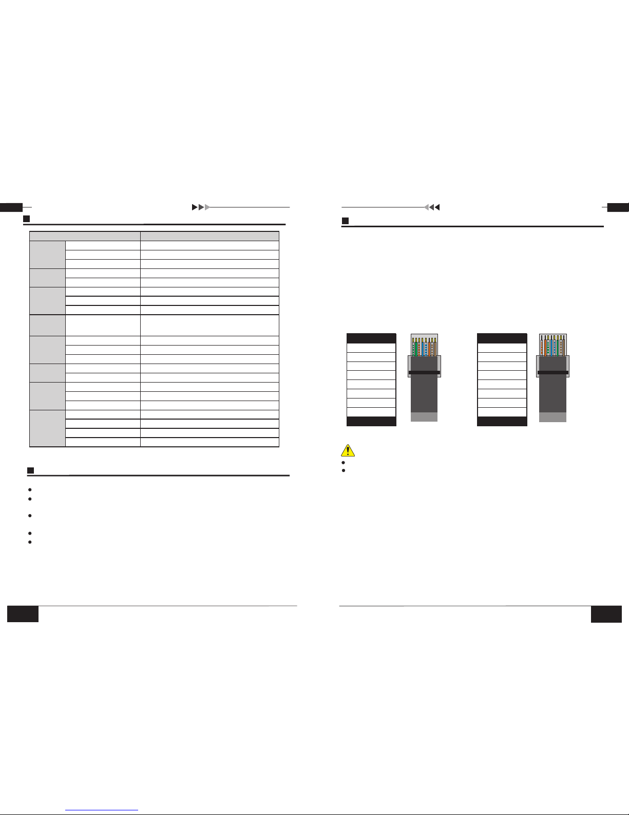
Wire sequence of RJ45 plug should conforms with EIA/TIA568A or 568B standards.
1) Shuck off about 2cm long of the insulating layer to expose the 4 pairs UTP cables;
2) Seperate the 4 pairs UTP cables and straighten them up;
3) Line up the 8 pieces of cables per EIA/TIA 568A or 568B standards;
4) Brunt cut the cables to leave 1.5cm wire exposed and make sure the wire ends are leveled off;
5) Plug 8 cables into RJ45 plug, make sure each cable is in each pin;
6)Then use wire crimper to crimp it;
7) Repeat above 5 steps to make the another end;
8) Using network tester to test the cable .
RJ 45 Making Method
Make sure if one end is EIA/TIA568B,the other end should also be EIA/TIA568B.
Make sure if one end is EIA/TIA568A,the other end should also be EIA/TIA568A.
pin color
white/green
green
blue
white/orange
white/blue
white/brown
orange
brown
1
2
3
4
5
6
7
8
pin color
1
2
3
4
5
6
7
8
white/green
green
blue
white/orange
white/blue
white/brown
orange
brown
EIA/TIA 568A EIA/TIA 568B
Notice
Table of contents
Popular Media Converter manuals by other brands

NEXIS
NEXIS VW8208 user manual

TR-Electronic
TR-Electronic CEV582M-4096/4096 PB 36ZB12FL Assembly instructions

Transition Networks
Transition Networks CBFTF1011-110 user guide

Snell & Wilcox
Snell & Wilcox Premier HD HD2200 Installation & operator's manual

LY International
LY International HS6813 user manual

Bosch
Bosch AMC MUX installation manual