IQ CV810 User manual

IQConference Cam
CV810
User Manual

Warning
Improper operations may damage the product structure and result in mechanical
failure. Please note the following tips.
Do not move the camera by
grabbing the head.
Move the camera by holding
the bottom with one or both hands.
Please do not rotate the lens and
holder manually no matter the camera is
power on or off; otherwise it may
damage the camera structure and result
in failure of camera self-check and
unable to start the camera.

1
Attentions
This manual introduces functions, installations and operations for this PTZ camera in details. Please read
this manual carefully before installation and use.
1. Cautions
1.1 Avoid damage to product caused by heavy pressure, strong vibration or immersion during transportation,
storage and installation.
1.2 Housing of this product is made of organic materials. Do not expose it to any liquid, gas or solids which may
corrode the shell.
1.3 Do not expose the product to rain or moisture.
1.4 To prevent the risk of electric shock, do not open the case. Installation and maintenance should only be carried
out by qualified technicians.
1.5 Do not use the product beyond the specified temperature, humidity or power supply specifications.
1.6 Wipe it with a soft, dry cloth when cleaning the camera lens. Wipe it gently with a mild detergent if needed. Do
not use strong or corrosive detergents to avoid scratching the lens and affecting the image.
1.7 This product contains no parts which can be maintained by users themselves. Any damage caused by
dismantling the product by user without permission is not covered by warranty.
2. Electrical Safety
Installation and use of this product must strictly comply with local electrical safety standards.
The power supply of the product is ±12V, the max electrical current is 2A .
3. Install
3.1 Do not rotate the camera head violently, otherwise it may cause mechanical failure.
3.2 This product should be placed on a stable desktop or other horizontal surface. Do not install the product
obliquely, otherwise it may display inclined image.
3.3 Ensure there are no obstacles within rotation range of the holder.
3.4 Do not power on before completely installation.
4. Magnetic Interference
Electromagnetic fields at specific frequencies may affect the video image. This product is Class A. It may cause
radio interference in household application. Appropriate measure is required.

2
Content
1. Camera Installation....................................................................................................................................................3
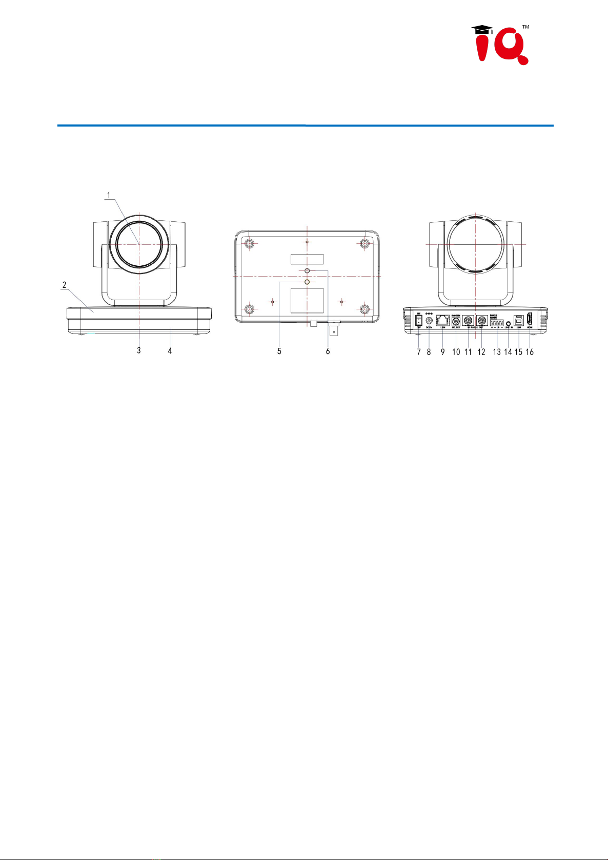
1.1 Camera Introduction............................................................................................................................................ 3
1.2 Interfaces and Connection................................................................................................................................. ..4
1.3 Mounting Brackets...............................................................................................................................................4
2. Product Overview...................................................................................................................................................... 8
2.1 Dimension............................................................................................................................................................8
2.2 Accessory............................................................................................................................................................. 8
2.3 RS-232 Interface..................................................................................................................................................9
2.4 Rotary DIP Switch............................................................................................................................................10
2.5 Main Features...................................................................................................................................................11
2.6 Technical Parameter...........................................................................................................................................11
3. Remote Control........................................................................................................................................................14
3.1 Match Code for Wireless Remote Control........................................................................................................ 14
3.2 Keys Introduction for IR Remote Control.........................................................................................................14
3.3 Menu Introduction............................................................................................................................................. 17
4. Network Configuration............................................................................................................................................19
4.1 Network Connection..........................................................................................................................................19
4.2 IE Login............................................................................................................................................................. 20
4.3 Streaming...........................................................................................................................................................21
4.4 Software Upgrading...........................................................................................................................................22
5. Serial Port Communication and Control................................................................................................................. 24
5.1 VISCA Protocol Return Command................................................................................................................... 24
5.2 VISCA Protocol Control Command..................................................................................................................24
5.3 VISCA Protocol Inquiry Command.................................................................................................................. 27
5.4 Pelco-D Protocol Command List...................................................................................................................... 29
5.5 Pelco-P Protocol Command List....................................................................................................................... 30
6. Maintenance and Troubleshooting.......................................................................................................................... 31
6.1 Camera Maintenance......................................................................................................................................... 31
6.2 Troubleshooting................................................................................................................................................32

3
1.Camera Installation
1.1Camera Introduction
Figure 1.1 Product Interface
1.Camera Lens
7.Power Switch
13.RS422/RS485 Interface
2.Camera Base
8.DC12V Input Power Supply Socket
14.Audio Input Interface(LINE-IN)
3.Indicator Light
9.LAN Port
15.USB3.0 Interface
4.Infrared Receiver
10.Rotary DIP Switch
16.HDMI Output Interface
5.Tripod Screw Hole
11.RS232 Control Interface(input)
6.Tripod Screw Hole
12.RS232 Control Interface(output)
The default address selected by the remote control camera is 1#. When the remote control is controlled, the
status indicator light flashes green;
The remote control camera address selection is wrong, the indicator light does not flash, the remote control
control is invalid.

4
1.2 Interfaces and Connection
1.3 Mounting Brackets
Notes:
Ceiling or wall mounting brackets can only be mounted on template and concrete wall.
For safety reason, plasterboard is not recommended.
1)Wall Mounting
Figure 1.3 Wiring Diagram
1) After power on and self-warming, the camera will automatically return to the preset 0 position if it’s pre-set.
2) The default address for the IR remote control is 1#. If the menu restored to factory defaults, the remote control
default address will restore to 1#.

5

6
2)Ceiling Mounting

7

8
2. Product Overview
2.1 Dimension
2.2 Accessory
Please check below standard and optional accessories when unpacking the box.
Standard Accessory
Optional Accessory
Power Adapter
Infrared Remote Control
RS232 Cable
Wireless Remote Control
User Manual
Ceiling Mount
USB3.0 Cable
Wall Mount

9
2.3 RS-232 Interface
1)RS-232 Interface Definition
Connection to PC or Camera Controller
Camera
WindowsDB-9
1.DTR
1.DCD
2.DSR
2.RXD
3.TXD
3.TXD
4.GND
4.DTR
5.RXD
5.GND
6.GND
6.DSR
7.IR OUT
7.RTS
8.NC
8.CTS
9.RI
2)Mini-DIN8-pin Port Definition
3)RS232(DB9) Port Definition
NO.
Port
Definition
1
DTR
Data Terminal Ready
2
DSR
Data Set Ready
3
TXD
Transmit Data
4
GND
Signal Ground
5
RXD
Receive Data
6
GND
Signal Ground
7
IR OUT
IR Commander Signal
8
NC
No Connection
NO.
Port
Definition
1
DCD
Data Carrier Detect
2
RXD
Receive Data
3
TXD
Transmit Data
4
DTR
Data Terminal Ready
5
GND
System Ground
6
DSR
Data Set Ready
7
RTS
Request to Send
8
CTS
Clear to Send

10
4)VISCA networking as shown below
Camera cascade connection
Camera 1
Camera 2
1.DTR
1.DTR
2.DSR
2.DSR
3.TXD
3.TXD
4.GND
4.GND
5.RXD
5.RXD
6.GND
6.GND
7.IR OUT
7.OPEN
8. NC
8.OPEN
Note: Camera has RS232 input and output interfaces, which can be cascaded according to the above methods
2.4 Rotary DIP Switch
Note: after the video format is modified by rotating dial code, it can take effect after power off
and restart. Turn the dial to C, D, E, F, power off and restart, the menu can display the video
format.
9
RI
Ring Indicator
Dial-up
video format
Dial-up
video format
0
4KP60
8
1080P30
1
4KP50
9
1080P25
2
4KP30
A
720P60
3
4K25
B
720P50
4
1080P60
C
video format to be set
on the menu
5
1080P50
D
video format to be set
on the menu
6
1080I60
E
video format to be set
on the menu
7
1080I50
F
video format to be set
on the menu

11
2.5 Main Features
This camera has perfect functions, superior performance and rich video output interfaces; Featuring with advanced
ISP processing algorithms, offering vivid and high resolution video with a strong sense of depth and fantastic color
rendition. It supports H.264/H.265 encoding which makes motion video more fluent and clear under low
bandwidth conditions.
4K UHD Resolution: 8.51M megapixel high quality SONY CMOS sensor. Resolution is up to 4K with frame rate
up to 60fps.
Optical Zoom Lens: 12X optical zoom lens and 70° wide angle lens.
Leading Auto Focus Technology: Fast, accurate and stable auto focusing technology.
Low Noise and High SNR: Super high SNR image is achieved with low noise CMOS. Advanced 2D/3D noise
reduction technology further reduces the noise while ensuring high image clarity.
Multiple video output interfaces: HDMI, USB3.0, LAN.
Multiple Audio/Video Compression Standards: USB3.0 interface supports MJPEG, H264, YUY2, NV12, H265;
support AAC, MP3 and G.711A audio compression, 8000, 16000, 32000, 44100, 48000 sampling frequency.
Multiple Network Protocol: Support ONVIF, GB/T28181, RTSP, RTMP protocols; Support RTMP push mode,
easy to be connected to streaming server (Wowza, FMS); Support RTP multicast mode; Support network full
command VISCA control protocol.
Control Interface: RS422 input(compatible with RS485), RS232 input/output, RS232 (cascade connection)
Multiple Control Protocol: Support VISCA, PELCO-D, PELCO-P protocols; Support automatic identification
protocols.
Built-in gravity sensor: Built-in gravity sensor, Support PTZ automatic flip function, convenient for installation.
Quiet Pan / Tilt Movement: With high accuracy step driving motor, camera can pan / tilt extremely quiet and
smooth.
Multiple presets: Up to 255 presets (10 presets via remote control).
IR / Wireless Remote Control: Users can choose IR remote control or wireless remote control according to
different conditions. 2.4G wireless remote control is not affected by the angle, distance or infrared interference.
Far-end-control is also available.
Multiple Application: Online-education, Lecture Capture, Webcasting, Video conferencing, Tele-medicine,
Unified Communication, Emergency command and control systems, etc.
2.7 Technical Parameter
Model
CV810
Camera Parameter
Optical Zoom
12X
View Angle
Parallel:6.55°(N)~69.4°(W)
Vertical:3.66°(N)~42.8°(W)
AV
F1.6 ~F2.8±5%
Sensor
1/2.8 inch SONY CMOS sensor
Effective Pixels
8.51M megapixel 16:9

12
Video Format
HDMI video format
4KP60,4KP50,4KP30,4KP25,1080P60,1080P50,1080I60,1080I50,
1080P30,1080P25,720P60,720P50
USB3.0 interface video format
YUY2/NV12: 1920×1080P30,1280×720P30,960×540P30,640×360P30,
640×480P30,320×176P30
MJPEG/H.264/H.265: 3840×2160P30,1920×1080P30,1280×720P30,
1024×576P30,960×540P30,800×448P30,640×360P30,640×480P30,320×176P30
USB3.0 is compatible with USB2.0 video format
YUY2/NV12: 640×360P30,640×480P30,320×176P30
MJPEG/H.264/H.265: 3840×2160P30,1920×1080P30,1280×720P30,
1024×576P30,960×540P30,800×448P30,640×360P30,640×480P30,320×176P30
Minimum
Illumination
0.05Lux(F1.8, AGC ON)
DNR
2D﹠3D DNR
White Balance
Auto / Manual/ One Push/ Specify color temperature
Focus
Auto/Manual/One Push Focus
Exposure Mode
Auto/Manual/Shutter priority/Aperture priority/brightness priority
Aperture
F1.8 ~F11 CLOSE
Shutter Speed
1/25~1/10000
BLC
ON/OFF
WDR
OFF/ Dynamic level adjustment
Video
Adjustment
Brightness, Color, Saturation, Contrast, Sharpness, B/W mode, Gamma curve
SNR
≥50dB
Input/Output Interface
Video Interfaces
HDMI,USB3.0(Type B compatible with USB2.0),LAN(POE),A-IN,RS232-IN,
RS232-OUT,RS422(compatible with RS485), Rotary DIP switch, DC12V Power Supply,
Power Switch
Video
Compression
Format
LAN Interface: H.265,H.264
USB 3.0 Interface: YUY2,MJPEG,H.264,H265,NV12
Audio Input
Interface
Double track 3.5mm linear input
Audio Output
Interface
HDMI,LAN,USB3.0
Audio
Compression
Format
AAC,MP3,G.711A
Network
Interface
10M/100M/1000M Adaptive Ethernet port, support POE power supply, support audio and
video output
Network
Protocols
RTSP,RTMP,ONVIF,GB/T28181; Network VISCA control protocol;
Support remote upgrade, reboot and reset
Control Interface
RS232-IN,RS232-OUT,RS422 compatible with RS485
Serial
Communication
protocol
VISCA/Pelco-D/Pelco-P
Baud Rate: 115200/38400/9600/4800/2400
USB
Communication
UVC(Video),UAC(Audio)

13
Protocol
Power Interface
HEC3800 outlet (DC12V)
Supply Adapter
AC110V-AC220V to DC12V/2.5A
Input Voltage
DC12V±10%
Input Current
<1A
Power
Consumption
<12W
PTZ Parameter
Pan Rotation
-170°~+170°
Tilt Rotation
-30°~+90°
Pan Control
Speed
0.1°/s~100°/s
Tilt Control
Speed
0.1°/s~45°/s
Preset Speed
Pan: 100°/s, Tilt: 45°/s
Preset Number
255 presets (10 presets via remote control)
Other Parameter
Stored
Temperature
-10℃~+60℃
Stored Humidity
20%~95%
Working
Temperature
-10℃~+50℃
Working
Humidity
20%~80%
Dimension
181mm(L)×115mm(W)×149mm(H)
Weight
1.15kg
Application
Indoor
Accessory
Package
Power Supply, RS232 Control Cable, USB3.0 Cable, IR Remote Control, User Manual
Optional
Accessories
Ceiling / Wall Mount (Extra Cost)

14
3. Remote Control
Remote control instructions: remote control is divided into two types: infrared remote control and wireless remote
control. Please read the following contents according to the actual remote control type.
3.1 Match Code for Wireless Remote Control
One to One Code Matching:
Press the "set" and "*" keys combined for 3 seconds, LED indicator starts flashing. Camera
receive the signal and power on, LED indicator will go off if code matching successfully.
The camera can be controlled by this wireless remote control only after one to one code
pairing. Otherwise please clear the code matching of this remote control, or use other remote
control to pair with the camera again.
If one to one code matching failed, the red LED light flashes for 20 seconds and then goes
off, camera will stop code match and turn on sleep mode; Press any key to wake up the
camera and re-match code.
Note: After code matching successfully, please select the camera address to control it.
Clear Code:
Press the "set" and "#" keys combined for 3 seconds, LED indicator starts flashing. Camera
will power off and on, the LED indicator will go off if clear code successfully.
Sleep Mode and Wake Up:
Press any key to wake up the camera from sleep mode.
3.2 Keys Introduction for IR Remote Control
1) In this manual, “press the key” means a click rather than a long-press, and a special note will be given if a
long-press for more than one second is required.
2) When a key-combination is required, do it in sequence. For example,“ 【*】+【#】+【F1】”means press“【*】”first
and then press“【#】” and last press“【F1】”.

15
1. Standby Key
The camera enters standby mode if long press 3s on standby key;
Long press 3s again on the standby key, the camera will self-check again and return to HOME position (If preset 0
position is set, the camera will return to preset 0 position).
2.Camera Selection
Select the camera address to control.
3. Focus Control
Auto: auto focus mode
Manual: manual focus mode
Focus + (near):Press【FOCUS +】key (Valid only in
manual focus mode)
Focus - (far): Press【FOCUS -】key (Valid only in
manual focus mode)
Press and hold the keys, the action of focus will keep
continue and stop as soon as the key is released.
4. Zoom Control
ZOOM +: press【ZOOM +】key to zoom in
ZOOM - : press 【ZOOM -】key to zoom out
Press and hold the keys, the action of focus will keep
continue and stop as soon as the key is released.
5. Set and Clear Presets

16
Set Preset: press 【SET PRESET】button, and then
press the number key 0-9 to set preset positions.
Note: 10 presets via remote control.
Call Preset: Press a number key 0-9 directly to call a
preset position.
Clear Preset: press 【CLEAR PRESET】button, and
then press the number key 0-9 to clear preset positions.
Note : press the【#】key three times continually to
clear all presets.
6. Pan/Tilt Control
Up: press Down: press
Left: press Right: press
Back to middle position: press“【HOME】”
Press and hold the up/down/left/right key, the pan/tilt
movements will keep running, from slow to fast, until it
runs to the endpoint; stop as soon as the key is released.
7. Menu Setting
【MENU】: Open / close the OSD menu
【HOME】:Camera lens back to the middle position;
Confirm button; Enter next menu
【↑】【↓】:Choose item
【←】【→】:Modify values
【BLC ON/OFF】:Turn on or off the back light
compensation
8. Camera Remote Control Address Setting
【*】+【#】+【F1】:Camera Address No.1
【*】+【#】+【F2】:Camera Address No. 2
【*】+【#】+【F3】:Camera Address No. 3
【*】+【#】+【F4】:Camera Address No. 4

17
9. Key Combination
1) 【#】+【#】+【#】: Clear all presets
2) 【*】+【#】+【6】: Restore factory defaults
3) 【*】+【#】+【3】: Menu set to Chinese
4) 【*】+【#】+【4】: Menu set to English
5) 【*】+【#】+【9】: Flip switch
6) 【*】+【#】+Auto: Enter aging mode
7) 【#】+【*】+Auto: Exit aging mode
8) 【*】+【#】+Manual: Restore the default user name,
password, and IP address
9) 【#】+【#】+【0】: Switch the video format to 4KP60
10)【#】+【#】+【1】: Switch the video format to 4KP50
11)【#】+【#】+【2】: Switch the video format to 4KP30
12)【#】+【#】+【3】:Switch the video format to 4KP25
13)【#】+【#】+【4】: Switch the video format to 1080P60
14)【#】+【#】+【5】:Switch the video format to 1080P50
15)【#】+【#】+【6】: Switch the video format to 1080I60
16)【#】+【#】+【7】: Switch the video format to 1080I50
17)【#】+【#】+【8】: Switch the video format to 1080P30
18)【#】+【#】+【9】:Switch the video format to 1080P25
Note: If the address of former remote control is not address 1 but another one from 2, 3,
4, the corresponding camera address will restore to address 1 when all parameters are
restored to factory default. User should change the remote control address to address 1.
3.3 Menu Introduction
Note: The modification valid only if exit the menu before save and power off.
1) Menu Control
【MENU】: Enter / exit the OSD menu or return to the previous menu
【HOME】:Enter next menu
【↑】【↓】:Choose item
【←】【→】:Modify values
2) English Menu

18
Table of contents
Other IQ IP Camera manuals