IQ IQVideo LCS610 User manual

IQVideo
Lecture Capture System
LCS610
——User Manual——

2/31

3/31
Contents
Chapter 1 System Components...................................................................5
1.1 Video Station Interface Description...................................................5
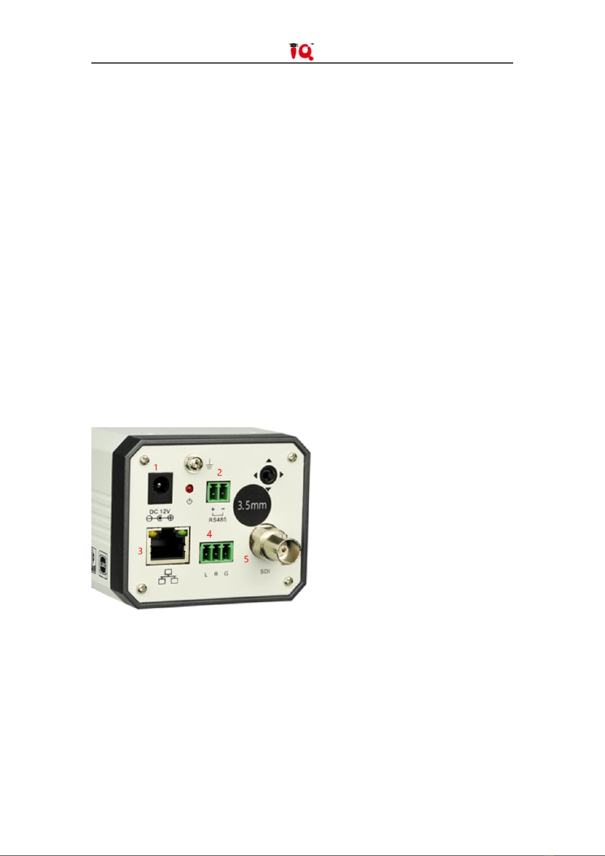
1.2 Teacher Camera/Student Camera Interface Description..................6
1.3 Microphone Audio Processor Interface Description......................... 7
1.3.1 Front Interface.................................................................................... 7
1.3.2 Back Interface..................................................................................... 7
Chapter 2 Installation Preparation..............................................................8
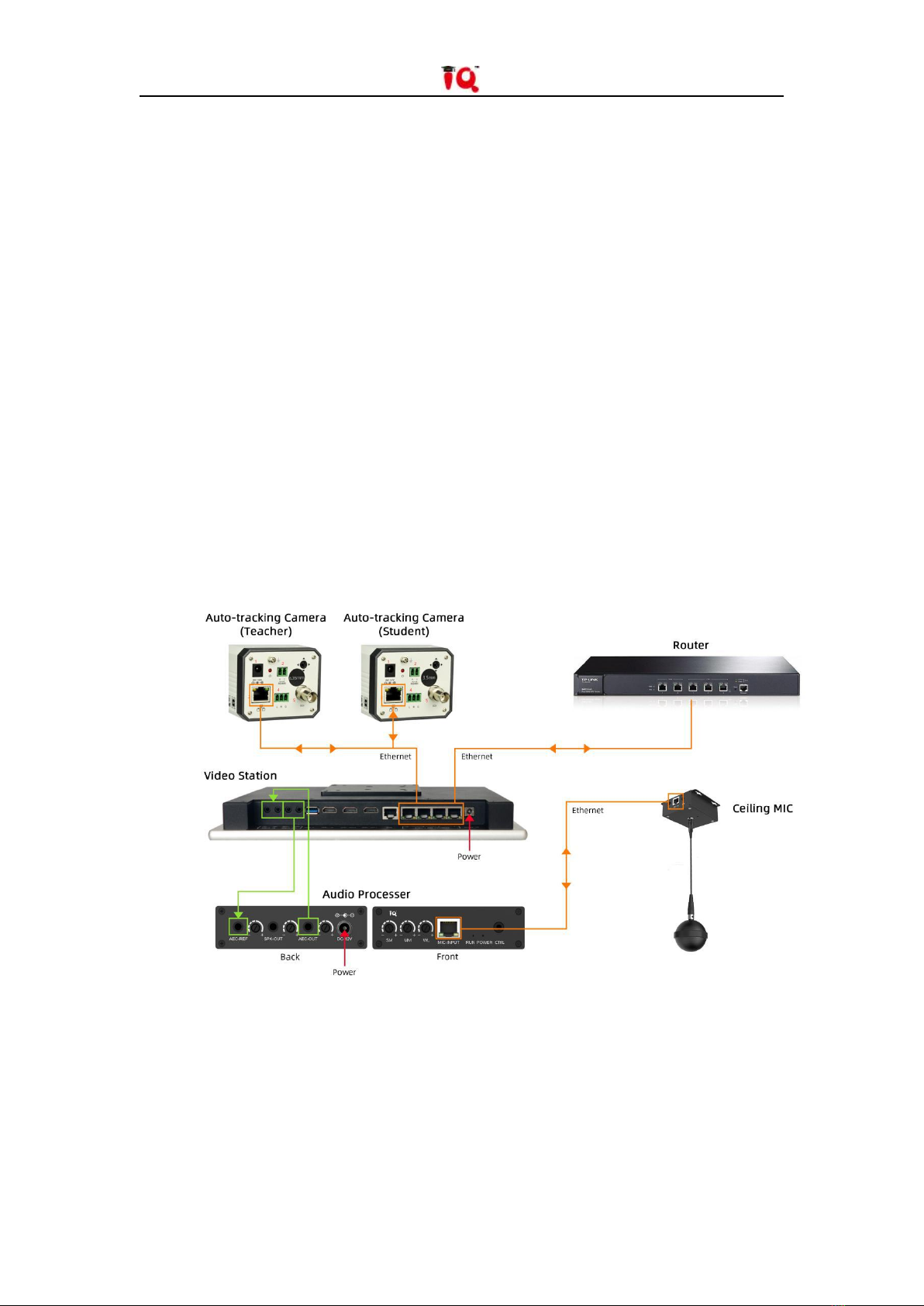
Chapter 3 Device Connection...................................................................... 8
Chapter 4 Video Station IP Settings............................................................ 8
Chapter 5 Camera IP Settings....................................................................10
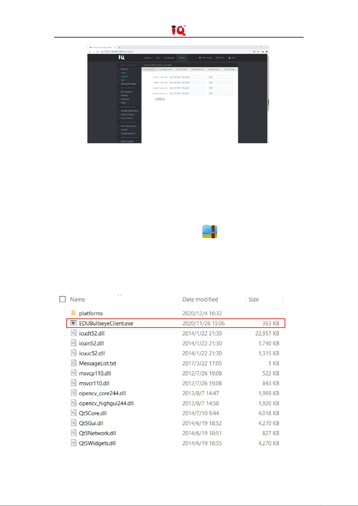
5.1 Configuration Software Installation.................................................10
5.2 Network Parameters Setting............................................................11
Chapter 6 Video Station Operation Instructions................................... 12
6.1 Local Recording.................................................................................12
6.1.1 Network Settings.............................................................................. 12
6.1.2 Director Settings............................................................................... 13
6.1.3 Local Recording.................................................................................14
6.1.4 Video Review and Export..................................................................15
6.2 Remote Recording............................................................................ 15
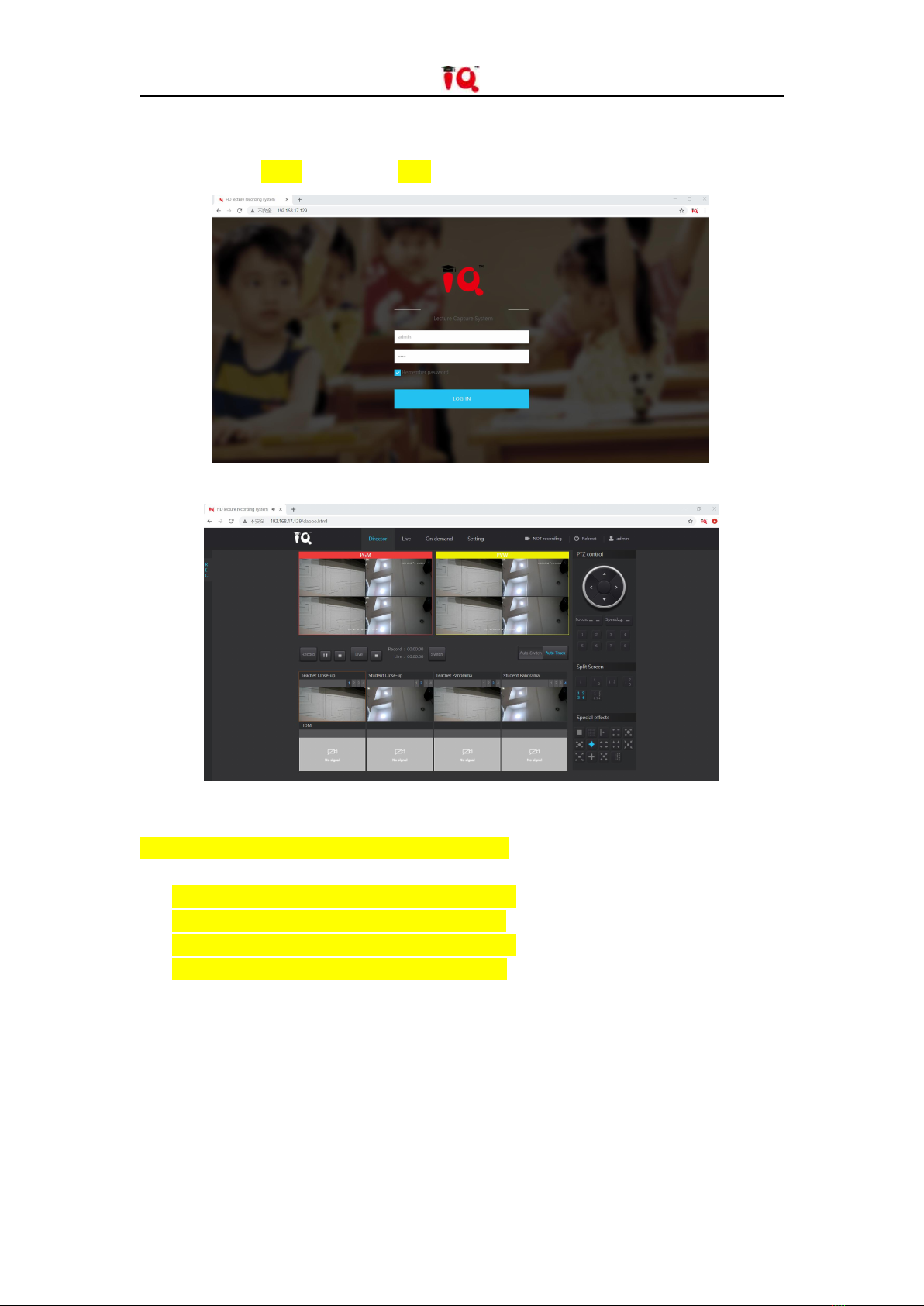
6.2.1 Log in to the Remote Director System............................................. 15
6.2.2 Remote Director Settings................................................................. 15

4/31
6.2.3 Watch Videos and Downloads Remotely......................................... 16
6.3 Live streaming over Internet............................................................17
Chapter 7 Recording System Parameter Settings.....................................17
7.1 Video Station Configuration.............................................................17
7.2 External interface............................................................................. 23
7.3 Intelligent Control.............................................................................24
7.4 User Management............................................................................25
7.5 System Management........................................................................27
Chapter 8 Abnormal problems and solutions...........................................29

5/31
Chapter 1 System Components
Video Station
Auto-tracking Camera (Teacher)
Auto-tracking Camera (Student)
Ceiling MIC
Microphone Audio Processor
1.1 Video Station Interface Description

6/31
1. DC-48 IN
Video Station Power In
2. 4-port POE 1000Mbps
4 Gigabit Ethernet POE Power Supply and Access to Webcam
3. COM
RJ45 Control Port, Support RS-232 Communication Protocol
4. HDMI-OUT2
Local Director Screen Output
5. HDMI-OUT1
Recorded Video Screen Output
6. HDMI-IN
Support Access to the Teacher’s Computer or Visual Presenter and Other HDMI Video
Signals
7. USB
Local Recording Video Export
8. AUDIO-OUT
Audio Recording Output to Audio Processor
9. AUDIO-IN
Audio Signal Input Such as Microphone
1.2 Teacher Camera/Student Camera Interface Description
1. DC 12V, Camera Power Interface
2. RS485 Device Control Port
3. RJ45, Gigabit Network Interface, POE Supported
4. 3-Pin Phoenix Contact Audio Line in
5. SDI Video Signal Transmission Interface

7/31
1.3 Microphone Audio Processor Interface Description
1.3.1 Front Interface
1. SM Input volume adjustment knob of wired vice microphone.
2. MM Input volume adjustment knob of wired main microphone.
3. WL Input volume adjustment knob of wireless main microphone.
4. MIC-INPUT Input interface of network port microphone.
5. RUN Device running indicator, flashing slowly indicates normal operation.
6. POWER Power indicator, keep it on after power on.
7. CTRL Debugging port.
1.3.2 Back Interface
8. AEC-REF Acoustic echo cancellation audio signal input interface, 3.5mm audio interface.
9. AEC-REF Rotate the AEC-REF volume adjustment.
10. SPK-OUT Stereo output to external amplifier or speakers, 3.5mm audio interface.
11. SPK-OUT Rotate the SPK-OUT volume adjustment .
12. AEC-OUT Stereo acoustic echo cancellation processed signal output interface, 3.5mm audio
interface.
13. AEC-OUT Rotate the AEC-OUT volume adjustment knob.
14. DC-12V Power port.

8/31
Chapter 2 Installation Preparation
Before setting, please prepare a computer (installed with tracking debugging software),
video station, tracking camera, and ceiling microphone.
There are two tracking cameras: teacher camera and student camera. The tail plate marked
7.35mm is the teacher tracking camera (teacher camera default IP: 192.168.2.88), and 3.5mm is
the student tracking camera (student camera default IP: 192.168.2.89). The installation height is
preferably between 2.2 meters and 2.5 meters.
Connect all devices and network cables, make sure all devices are in the same LAN, and
ready for setting.
Chapter 3 Device Connection
Chapter 4 Video Station IP Settings
Connect the computer to the video station with a network cable. Check if the default IP
address of the video station is 192.168.1.212. Change the computer’s IPv4 address to the same

9/31
network segment with the video station (e.g. 192.168.1.112). Access the video station's default IP
address through a computer browser (Google browser is recommended).
Enter username:admin password:8888
Pic:Access video station IP address
Pic:Home page after login
Enter the settings page to modify the network address of the Video Station to:
192.168.XXX.XXX (depending on the local area network), re-enter the modified IP address on the
web page, and enter the settings page to add the camera network address:
rtsp://192.168.XX.88/video1(Teacher Panorama)
rtsp://192.168.XX.88/video2(Teacher Close-up)
rtsp://192.168.XX.89/video1(Student Panorama)
rtsp://192.168.XX.89/video2(Student Close-up)
The camera IP address setting ensures that the network segment is consistent with the
video station. Restart the video station after saving the parameters.

10 /31
Pic:Connect the camera in the settings
Chapter 5 Camera IP Settings
5.1 Configuration Software Installation
Unzip the Camera Configuration Software
EDUTrackerClie
nt1.4.4.zip
to the specified location,
double-click to open the software as shown in the figure below;

11 /31
Pay attention to select the corresponding Network Connection, click search to display all devices
in the current network.
5.2 Network Parameters Setting
Click to select the camera in the device list on the left, the network parameters and software
version information of the current device are displayed on the right, and click to modify the IP
address to make it consistent with the video station settings. After the modification is completed,
saving the settings without restarting, as shown below:

12 /31
Chapter 6 Video Station Operation
Instructions
6.1 Local Recording
Pic:Video station power on state
The login interface will be displayed after power-on, and the system default login password
8888.
6.1.1 Network Settings
Pic:Network setting interface

13 /31
Click the logo icon in the upper left corner to pop up the network settings page. Support
manual input of IP information and automatic acquisition of router DHCP settings. Click “Save” to
take effect.
6.1.2 Director Settings
Click "Setting" to enter the director settings
Pic:Director page
Split-screen: Before class, teachers can choose a suitable split-screen mode according to
class needs .
Pic:Split screen selection
1. Select the split screen mode you want
2. Enter "split screen settings", select the camera image to be displayed on each split screen
For example: in the case of four-split screen, there are four numbers 1/2/3/4 in the
split-screen setting, corresponding to the four split-screen pictures. If you want to display camera
3 on screen 4, select 4 in this row.

14 /31
Others: The application module mainly sets the information added in the video.
Pic:One-click apply button
Including adding subtitles, time, course information, recorded opening and ending , logo, etc. to
the video.
Tracking: Select "Switch" — — the recording system will automatically switch the screen, at this
time the manual split screen cannot be changed.
Select "Tracking"——the camera automatically tracks the movement of the teacher, it is
recommended to keep the selected state.
6.1.3 Local Recording
Click "Record" to start recording video, click "Stop" to stop recording, click "Lock" to freeze
the HDMI input source screen when there is HDMI video source input

15 /31
6.1.4 Video Review and Export
Export: Insert a U disk, and export the video in "Download"
6.2 Remote Recording
6.2.1 Log in to the Remote Director System
Pic:Remote director login interface
Make sure that the computer and the video station are in the same LAN. Open the browser
and enter the IP address of the video station in the browser.
(default IP: http://192.168.1.212, you can view the existing IP on the Video Station)
Enter the login interface of the Remote Director System, as shown in the figure above.
Enter the username: admin Password: 8888 (same as the password of the local director),
and then Login to enter.
6.2.2 Remote Director Settings

16 /31
Through the preview window, you can view the teacher panorama, teacher close-up,
student panorama, student close-up, HDMI input screen.
Select the split-screen mode you want, and view the effect of split-screen in the "Preview
Screen".
The position of each lens in the split screen can be modified by setting the number of each
lens.
Click "Switch" to switch the preview screen to the PGM screen. At this time, the screen of
the video station will change synchronously.
The actual recording screen is subject to the PGM screen.
The "smart switch" button is a toggle switch. When the button is turned off, the tracking will
not be switched, and when the button is turned on, the camera will switch automatically.
The "Smart Tracking" button is a tracking switch. When this button is turned off, smart
tracking is not performed. When this button is turned on, automatic lens tracking is performed.
6.2.3 Watch Videos and Downloads Remotely
Pic:Video on demand page
The recorded video is automatically maintained to the “On demand” page.
A single video automatically displays video screenshots, the number of simultaneous
recording channels, time recording duration, and recording time information.
Search toolbar that supports searching videos by date.

17 /31
6.3 Live streaming over Internet
Pic:Streaming address setting
In the Remote Director System -> External interface -> Live streaming -> RTMP fills in the
third-party live broadcast address and saves it.
Click “Live” on the main interface of the video station, or click “Live” on the Remote Director
System to start streaming to the live broadcast platform. In this time enter the Remote Director
System -> Live, when you can view the live preview on the live page, it means the streaming is
successful.
Chapter 7 Recording System Parameter
Settings
7.1 Video Station Configuration
Network
Display the network card information and IP information of the current video station, support
manual setting of the video station address; support automatic acquisition of the IP address.

18 /31
Pic:Network settings page
Codec
Local Stream Parameters
Mainly used to set the code rate of the recorded video, and generally do not modify it;
Pic:Local live broadcast and recording parameter settings
Local Remote Live Broadcast Parameters
If you use public network live broadcast, you can freely adjust the code rate according to the
school's bandwidth, and generally do not modify it;

19 /31
Pic:Remote live broadcast main stream parameter setting
Pic:Remote live broadcast AUX stream parameter setting
Audio Codec Parameters
Display the current audio acquisition format;

20 /31
Pic:Audio codec parameter settings
Channel
Channel parameters
The channel parameters are used to dock the video information of the camera, and each
modification needs to be restarted to take effect;
Pic:Channel parameter setting
Recording Parameters
Channel selection—set multi-channel recording, the default recording director channel, the
director channel is not selectable, support up to 5 channels to record at the same time.
File format —choose to record files in FLV/MP4 format, and use MP4 format to record by
default
Duration limit —in the case of long-term recording, the video will be automatically cut,
which can be set to 1/2/3 hours
Pop-up settings—after clicking the record button, whether to pop up a confirmation dialog
box
Countdown recording —after clicking the “Record” button, whether to prompt to start
recording countdown, 0 means no timing, can be set to 3/5/8/10 seconds
Table of contents
Popular Network Hardware manuals by other brands

deZem
deZem HarvyLR-36 User manual and technical data

8e6 Technologies
8e6 Technologies Enterprise Filter Authentication R3000 user guide

Ruijie
Ruijie Reyee RG-EST Series Configuration guide

LUX LUMEN
LUX LUMEN ArtNet node manual

Fortinet
Fortinet FortiAP 431G quick start guide

DPT
DPT SmartRAID V user manual