Iris Innovations IRIS740 Original operating instructions

IRIS740
(c)2018 Iris Innovations Limited. All Rights Reserved. v01.00 16/03/18. E&OE
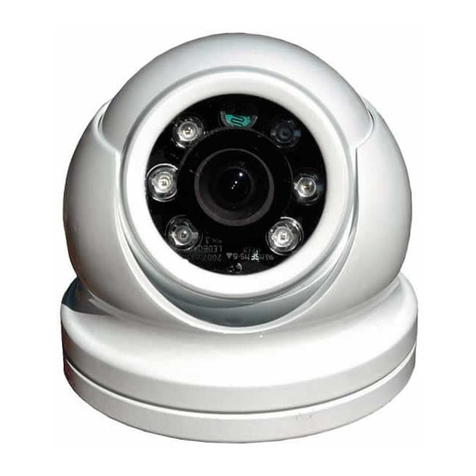
Through Hull Network IP Camera - 2MP
INSTALLATION &
OPERATION GUIDE
740-460-2MP

Important Notices. Read before Use:
This instruction manual is intended for administrators and users of the IRIS460 and 740 IP Cameras, including
instructions for using and managing the camera on your network. The use of video surveillance devices can be
prohibited by laws that vary from country to country. It is the user’s responsibility to ensure that the operation of
such devices is legal before installing this unit for surveillance purposes.
Before installing the IP Camera, please read and follow all the safety and operating instructions to avoid any
damages caused by faulty assembly and installation. The user must adhere to all the warnings on the product
and in this manual.
Liability
Every reasonable care has been taken in the preparation of this instruction manual. Iris can not be held
responsible for any technical or typographical errors and reserves the right to make alterations to the product
and manuals without prior notice. Iris makes no warranty of any kind with regard to the material contained within
this manual, including, but not limited to, the implied warranties of merchantability and fitness for a particular
purpose. The user should verify the relevant information is current and complete before placing orders. All
products are sold subject to Iris’ terms and conditions of sale at the time of order acknowledgement.
Iris shall not be liable nor responsible for the applications and resale of its products or bundled software with
statements different from or beyond the specification/parameters stated by Iris. Iris is under no obligation to
provide any further technical support service or product/software alteration beyond Iris’ representation.
Regulatory Information
Disposal of Waste Equipment by Users in Private Household in the European Union.
This symbol on the product or its packaging indicates that it must not be disposed of with
your other household waste. Instead, it is your responsibility to dispose of your waste
equipment
by handing it over to a designated collection point for the recycling of waste electrical and
electronic equipment. The separate collection and recycling of your waste equipment at the
time of disposal will help to conserve natural resources and ensure that it is recycled in a
manner that protects human health and the environment. For more information about where
you can drop off your waste equipment for recycling please contact your local city office,
your
household waste disposal service or the shop where you purchased the product.
This device has been tested and found to comply with the limits for a Class B digital device,
pursuant to Part 15 of the FCC rules. These limits are designed to provide reasonable
protection against harmful interference in a residential installation. This equipment generates,
uses and can radiate radio frequency energy and, if not installed and used in accordance
with the instructions, may cause harmful interference to radio or television reception.
However, there is no guarantee that interference will not occur in a particular installation.
If this equipment does cause interference to radio and television reception, which can be
determined by turning the equipment off and on, the user is encouraged to try to correct
the interference by one or more of the following measures: Reorientate or relocate the
receiving antenna; Increase the separation between the equipment and the receiver,
connect the equipment to an outlet on a different circuit from that to which the receiver is
connected; consult the dealer or an experienced radio / TV technician for help.
We hereby declare that the product is in compliance with the essential requirements and
other relevant provisions of European Directive 2004/108/EC, the RoHS Directive
2011/65/EU.
(c)2018 Iris Innovations Limited. All Rights Reserved. v01.00 16/03/18. E&OE

Warnings & Important Product
Information
WARNING: Installation and Operation
This product must be installed and operated in accordance with
these instructions. Failure to do so may result in poor product
performance, damage to the product or vessel and or personal
injury. Installation should only be carried out be qualified
personnel or by persons competent in electrical systems.
WARNING: Power Supply and Grounding
Ensure the boats power supply is switched off during
installation. Ensure suitably rated circuit breakers / fuses are
used in the installation of the product in accordance with the
electrical values shown in the technical specifications of the
product. Never switch on power until the power connections are
correctly terminated in accordance with the information provided
in this document. Do not connect or disconnect the product with
the power supply switched on. Never disconnect the DC ground
with the power supply on.
WARNING: Wiring terminations
Where the products video, power and data terminations are
extended, ensure that suitable connectors are used and that the
point of termination for each cable is adequately protected
against moisture ingress. Ensure correct polarity is strictly
observed. Do not cut or remove cable connectors without prior
permission from Iris Innovations Limited.
WARNING: Do Not Open the Unit
There are no user serviceable parts within the product so there s
no need to open the device. The product has been certified to
IP66 standards, however, submersion or the product or
exposure to high pressure washing will invalidate the warranty.
WARNING: Disclaimer
This product is intended to be used only as an aid to navigation
and must never be used as an alternative to correct navigational
practices and judgements made on the basis of approved
navigation methods. It is the users responsibility to observe
correct and proper navigational skill when using this product.
Only officially approved charts and notices to mariners contain
the current information required for safe navigation.
Operating the camera or viewing the video input whilst the
vessel is moving could cause a distraction and result in
accidental collision resulting in property damage, injury or death.
Iris Innovations cannot be held liable for any incidental, special,
indirect or consequential damages whether resulting from the
use, misuse or inability to use this product.
CAUTION: Switch Camera Off When Not in Use.
To prolong the operation life of the the cameras sensor we
strongly advise that power to the camera is routed via a
dedicated switch.
CAUTION: Service and Maintenance
This product contains no user serviceable parts. Please refer all
maintenance and repair issues to your authorized Iris
Innovations dealer. Any unauthorized work to the product may
affect the warranty.
CAUTION: Care and Cleaning
This product is a sensitive piece of electronic, imaging
equipment and must be handled and treated accordingly. Do not
drop or shake the unit during installation. Avoid exposure of the
imager to direct sunlight where possible as this may degrade the
cameras performance over time.
When cleaning the device, ensure power is switched off. Clean
the camera housing with a soft cloth. Moisten the cloth and use
a mild detergent if required. The lens window has a protective
coating which may suffer damage as a result of improper
cleaning. To clean the lens window use a soft cotton cloth.
Moisten with clean water if necessary. For further advise on
cleaning the lens window, contact Iris Innovations.
INFORMATION: Product Disposal and Recycling
Dispose of this product in accordance with the WEEE Directive.
The Waste Electrical and Electronic Equipment (WEEE)
Directive requires the recycling of waste electronic and electrical
equipment. Iris Innovations supports the WEEE policy and
politely request you observe correct disposal methods. For
further information on how to correctly dispose of this product
please contact Iris Innovations.
Please recycle unwanted packaging and documentation. The
cardboard carton, all paper manuals and documents and the
protective plastic bag in which the camera is shipped are widely
recyclable. Please check with your local recycling plant for
confirmation.
(c)2018 Iris Innovations Limited. All Rights Reserved. v01.00 16/03/18. E&OE
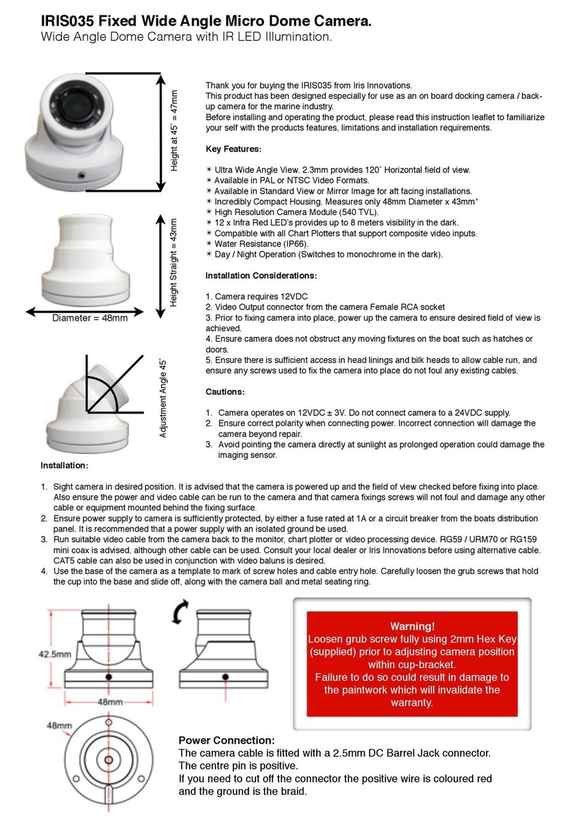
Overview of Key Features
Hereʼs a brief list of some of the IRIS740ʼs key features:
•1280 x 720P Resolution Camera Module
•Mechanical IR Cutout filter for True Day / Night Operation
•Switches to Monchrome in Low Light for improved clarity.
•Low Power 12VDC Operation <100mA
•IP68 Ingress Protection
•Rugged Housing
•PoE Option - With Integrated PoE Filter
•Compatible with ONVIF compliant Chart Plotters such as the
Raymarine Axiom and all other Raymarine network MFDʼs
running Lighthouse II & III software.
Contents of Package
Please unpack your IRIS460 and check to make sure the
following items are included. If there are any items missing
please contact your Iris dealer:
•1 x IRIS740 Through Hull Camera
•1 x Lock-Nut
•2 x Rubber Spacers
•1 x Instruction Manual
•1 x Water Resistant RJ45 connector kit
PoE Versions of the camera feature an integrated PoE filter.
About IP Cameras
An IP camera usually combines a high definition CCTV type
camera sensor with additional encoding circuitry and software to
convert the signal from and communications to the camera into
a digital format that can be accessed via the internet or an
ethernet based network.
The circuitry within the camera literally hosts itʼs own website.
IP cameras are simply CCTV cameras with integrated video web
servers. Therefore when you use your internet browser or
camera software to view your camera, you are merely
downloading a website hosted on the camera with live video.
Because the video signal between the sensor and encoder
remains digital, and doesnʼt have to be converted to an
analogue signal, higher resolutions can be achieved than
standard analogue cameras.
IP cameras can usually be viewed by multiple clients across a
network, which simplifies cabling reducing costs, whilst
maintaining the integrity of the video signal.
Power over Ethernet
Power over Ethernet (PoE) is a method of sending power to a
network device (such as the IRIS740) along the network cable,
this eliminating the need for separate power cables and
connections.
The power is introduced to the network cable via a PoE Injector.
This can be a single or multichannel device that acts like a
network hub whilst also ʻinjectingʼthe power onto the twisted
pair cable.
Traditional PoE devices operate at 48VDC which means on
board, an AC mains transformer is required to power the
injector. This is an issue if the boat only has DC power which is
often the case. AC powered units are unfavourable also
because they do not conform to marine standards for electrical
emissions and interference.
Iris produce a range of marine certified, DC voltage PoE
injectors which operate between 8~36VDC and are EN60945
and EN55022 compliant.
The most common classification for PoE devices is
IEEE802.3af-2003. This provides up to 15.4W of power but the
consumption is limited to 350mA so may not be powerful enough
to drive a PTZ device.
Recently, IEEE802.3at has become the standard. This can
handle up to 25.5W and is sometimes referred to as PoE+.
(c)2018 Iris Innovations Limited. All Rights Reserved. v01.00 16/03/18. E&OE

Installation: IRIS740
WARNING:
Installation of the IRIS740 necessitates a hole being cut into the structure of the vessel. Although guidelines are
provided below, the responsibility to ensure the camera is installed correctly and is sealed sufficiently to prevent
water ingress belongs to the installer, who must be suitably competent. Iris Innovations Limited and Iris
Innovations USA Corporation accept no liability whatsoever for issues that may arise as the result of improper or
sub stand installation that results in damage caused directly or indirectly as a result of leakage.
IMPORTANT:
Always ensure that the vessel’s power source and battery are disconnected prior to installation
Ensure a suitable fuse or circuit breaker are used. Iris recommend a 3A fuse.
Prior to installation, ensure there is sufficient space within the vessel to accommodate the camera,
taking into consideration room to tighten the cameras lock nut and facilitate access to connect and
disconnect the cable.
Although the camera housing and rear connector are waterproof, the PoE injector may not be. Ensure
this is installed well away from any moisture or direct heat sources.
ALWAYS POWER UP PRIOR TO DRILLING ANY HOLES TO ENSURE YO UARE INSTALLING THE
CAMERA IN A POSITION THAT WILL DELIVER THE DESIRED FIELD OF VIEW!
Procedure:
1)!Locate the camera as desired, taking into consideration internal or external obstacles that may affect
!the performance of the camera or inhibit the installation.
2)!The camera should be positioned on a flat surface. Ensure the external surface of the hull (or
!transom) are even and parallel. It may be necessary to sand or grind the surface.
3)"Once the installation area is prepared, drill a 90mm (3.54”) hole using a suitable pilot hole and hole "saw.
4)!Ensure the inner hull surface is sealed to prevent water intrusion into the hull before the camera is
!secured in place.
5)!Ensure that the hull surface is free from dirt, grease and debris. Remove anti-foul from the hull
!surface where the camera bezel will sit.
6)!Use a suitable marine adhesive sealant (3M 4200 for example) to apply a liberal bead of sealant
!around the entire circumference of the back side of the bronze bezel. A channel is machined into the
!back of the bezel - ensure this is completely filled with sealant.
7)"Apply a bead of sealant around the edge of the 90mm (3.54”) hole.
8)"Carefully slide the camera into the hole, ensure the orientation of the camera is as required. The
"camera is shipped with a removable stick-on arrow to indicate the ‘top’ of the cameras field of view.
9)!From inside the vessel, slide the rubber spacer rings over the camera shaft as required to ensure the
!lock nut will provide a suitably tight fixing. Two rings are supplied.
10)!Screw the lock nut in place and hand tighten. Do not lock fully in place at this stage.
11)!Connect the waterproof RJ45 plug into the back of the camera. Details on connecting to the network
!via a PoE injector are listed above.
(c)2018 Iris Innovations Limited. All Rights Reserved. v01.00 16/03/18. E&OE
Procedure (Continued…):
12)!Ensure the camera orientation is as desired. Make any changes to the cameras orientation now
!before the sealant cures and the lock nut is fully tightened.
13)!Disconnect the cable from the camera.
14)!Follow the sealant manufacturers instructions on curing time before fully tightening the camera lock
!nut.
15)!From inside the vessel, apply another bead of sealant fully around the circumference of the camera
!shaft.
16)!Allow the sealant to fully cure before putting the boat back into the water.
17)!Connect the waterproof CAT5 cable to the camera connector, ensuring the connector sits true in the
!receptacle and the connector lock-nut is fully tightened without cross threading.
18)!Now connect the cable to your network and follow the setup instructions below.
DO NOT LAUNCH THE VESSEL UNLESS THE SEALANT IS FULLY CURED IN ACCORDANCE WITH THE
SEALANT MANUFACTURERS INSTRUCTIONS AND YOU ARE SATISFIED THERE ARE NO LEAKS.
Setup
1. Connect the camera to a powered Ethernet source so that the unit is connected directly or indirectly to a
DHCP server.
2. The camera will adopt an I.P. address provided by the DHCP server, and will initially be displayed on the host
as a new attached device with name “-“ (Please refer to Router/DHCP server manual for relevant instructions
on performing this).
3. Once this is connected, new I.P and network details can be set via the Network setup page.
4. In the event of there being problems connecting the camera to your network, please contact your network
administrator or IP specialist quoting the cameras individual MAC address which can be found printed on the
carton label.
By default the camera is set to DHCP. Once connected directly or via your network to a DHCP router or server,
the camera should automatically assume the address it has been assigned.
A software discovery tool is provided with the camera to assist camera discovery and assigning addresses if
necessary. The tool is an executable program which can be copied onto your computer and run directly. Once
opened, the discovery tool can be set to SCAN the network for any connected IRIS404 or 740 cameras. It does
this by broadcasting specific information across the network which only an Iris camera will respond to. In doing
so, the camera will return it’s current IP address. The tool can be used to assign a new address if required.
Details on the SADP Tool are listed below.
(c)2018 Iris Innovations Limited. All Rights Reserved. v01.00 16/03/18. E&OE
Apply Sealant (See Guidelines Above)

How to fit Field Installable
Waterproof RJ45 Jacket
When installing in an external location, or any position that
will be prone to moisture ingress or harsh weather, it is
important the the waterproof RJ45 connector (supplied) is
used to protect the cameras connections.
Part No
Description
1
Cameras Network Interface Socket
2
O Seal
3
RJ45 Network Connector
4
Waterproof Endcap
5
Rubber Gasket
6
Lock Nut
7
Network cable to Router / Switch / Hub / etc..
Method
Step.1:
Feed the plug-less network cable (7) through the lock nut
(6), waterproof rubber gasket (5) (ensuring the rubber
gasket inset ridge faces the end-cap (4).
Step.2:
Crimp an RJ45 Network plug (3) onto the end of the cable
in accordance with the diagram below, taking care to
ensure the wires are terminated in the correct order and
are not crossed.
Step.3:
Place the O Seal (2) onto the end of the cameras network
interface socket (1).
Step.4:
Insert the network plug (3) into the cameras network
interface socket (1).
Step.5:
Insert the waterproof rubber gasket (5) into the waterproof
end-cap (4) and secure lock nut (6) with the waterproof
end cap (4).
Step.6:
Align the snap on waterproof end-cap (4) with the notch on
the cameras network interface socket (1) and then secure
the waterproof end-cap (4) to the cameras network
interface socket (1).
(c)2018 Iris Innovations Limited. All Rights Reserved. v01.00 16/03/18. E&OE
Pin No
Wire Colour
1
White / Orange
2
Orange
3
White / Green
4
Blue
5
White / Blue
6
Green
7
White / Brown
8
Brown
12VDC Models (Non PoE)
Non PoE versions of the camera have a separate DC
Barrel Jack and Socket style connection. A screw
terminal connector is supplied with these cameras. Care
should be taken to observe polarity of the power wires
and to ensure the connection is sufficiently protected
from moisture ingress.

Configuring the Camera over the
LAN
WARNING: Stay Secure!
When connecting any device to a network with access
over the internet brings risks to the security of your
network and your data. Your IRIS740 features built in User
Name and Password authentication but it is also your
responsibility to strengthen your network security where
ever possible. Please contact your IT expert for further
advise. Iris cannot provide support with any aspect of your
network security, other than the cameras built in security
settings.
Basic Setup: Single Camera / Computer
The diagram below shows a very basic setup, with a single
camera being viewed on a PC (or laptop).
Use a standard 568B ethernet CAT5 cable to hook your
computer up to the PoE injector, and then another 568B
cable to hook the camera up to the injector.
With this type of installation, you must ensure the IP
address of the camera is in the same range as the network
adapter in your computer used to communicate with the
camera. Consult documentation for your computer for
information on how to view (and edit) your network adapter
IP address.
The camera is set as default to DHCP, which means it has
no IP address set, and awaits for a router on your network
to assign the address.
To find your camera on the network, use an IP camera
discovery tool, or an ONVIF Device Manager.
A great Onvif Device Manager can be found here:https://
sourceforge.net/projects/onvifdm/
Once you’ve downloaded and installed the Device
Manager software, open the program and then click the
REFRESH button at the bottom of the device list on the left
hand side. If everything is hooked up correctly, the details
of your camera, including its IP address, will be displayed
in the list.
If the cameras IP address falls outside the range of the IP
address of your computers network adapter, you’ll have to
change the address on your adapter so it corresponds
with the address of the camera. Once this is done (and
you’ll usually need to reboot your computer) you should
simply be able to open your web browser, type the IP
address of the camera into the address bar and access the
camera. From here, if required, you can change the IP
address of the camera as desired - back to the original
address range of your computer for example. If you do
this, then you will also have to change the address of your
network adapter back to its previous range.
Basic Setup: Single Camera / Computer via Router
using DHCP (default)
The diagram below shows a simple one camera / one
computer device, but this time a router is used to manage
your network devices and address allocation.
As mentioned previously, the camera as default is set to
obtain its IP address automatically via DHCP. This means
that once connected, your router will detect the device and
assign it an IP address within its designated range (refer to
the documentation for your router for further details). You
must also ensure the network adapter for your computer is
set to obtain its address via DHCP.
(c)2018 Iris Innovations Limited. All Rights Reserved. v01.00 16/03/18. E&OE
Operation
IP Addressing & DHCP (Dynamic Host Control
Protocol).
Devices on your network require their own, unique IP
address. Your camera is factory set as DHCP (Dynamic
Host Control Protocol).
DHCP Addressing
DHCP allows devices on the network to receive their IP
address automatically from a server (or a device on the
network that acts as a server - such as a Raymarine MFD).
Nowadays, pretty much all routers have a DHCP server
feature, which usually just needs enabling and configuring.
Care should be taken on larger networks to ensure there
are no conflicts if multiple routers or devices are configured
as DHCP servers. Please refer to your IT specialist for
further details if you are unsure.
Raymarine MFD’s
For Raymarine MFD’s, including Axiom models, running
Lighthouse 2 or higher, all you need to do is connect the
camera to your Raymarine network and wait! Your
Raymarine device will take a few minutes to assign the
camera address at first, but once assigned, your camera
should appear within a short while after the MFD boots up
and initializes.
NOTE: The first time you hook your camera up to the
Raymarine it may take some time for the MFD to discover
the camera. This is normal.
Static (or Fixed) IP Addressing
If you are not using a DHCP server, you will need to log
onto the camera and assign an address to fit in with your
network address range. This sounds obvious, and like it
should be a basic step, but can actually be a major
challenge, as you can only log into the camera if its
address is in the same range as your network. If you do
not have experience in this field we recommend you
consult your IT specialist, as making undesirable changes
to your settings could result in major network problems.
For further details, please contact your Iris dealer.
Discovering your Camera
To discover your camera on your network you can check
your router for attached devices (if using DHCP) or use a
software discovery tool, or an ONVIF device manager.
A great Onvif Device Manager can be downloaded from
here:https://sourceforge.net/projects/onvifdm/
Remember, you’ll only be able to find a device on your
network if it’s in the same IP address range. If you are
unsure how to do this, consult your IT specialist.
Once you have found, or set your cameras address, you
can log on to set up and view your camera.
Logging Into your Camera
From your browser, type in your cameras IP address. The
login page from the camera will be loaded up (see above).
The default log in details are as follows:
USER NAME: admin
PASSWORD:
No password is set as default.
Once you’ve entered the correct user-name and password
the main window will be displayed. You can change the
default user name and password from the cameras Set Up
window.
(c)2018 Iris Innovations Limited. All Rights Reserved. v01.00 16/03/18. E&OE

Main Window
(c)2018 Iris Innovations Limited. All Rights Reserved. v01.00 16/03/18. E&OE
Local
Settings
Defines path on local PC for storing
snap-shots and video
Live View
Displays the live view from the camera
Remote Settings
Accesses Camera, Network and
System Setting pages.
Logout
Logs out of the cameras interface.
Playback
Used to search for stored snap-shots and
videos as defined in Local Settings.
Aspect Ratio
Aspect Ratio
Camera Title
Can be toggled ON/OFF or re-labelled
in Settings Menu
Time & Date
Can be toggled ON/OFF or adjusted
in Settings Menu
Video Definition
Toggle between Standard Definition (1280x720)
or High Definition (1920 x 1080)
Volume
Not Enabled on IRIS460
Full Screen
Scales Live Video Panel to
Full Screen
Microphone
Not Enabled on IRIS460
Snapshot
Stores snap shot to path
defined in Local Settings
Video
Stores video to path
defined in Local Settings
Zoom
Once enabled, allows user to
draw ‘Region of Interest’
which will fill the screen

Playback Window
Snap-Shots and Videos from the IRIS460 can be stored on
a local network device, such as a PC. To define the
storage path, format and duration, use the LOCAL
SETTINGS panel (see below).
To search for files, set your desired start time (STime) and
end time (ETime) and hit QUERY.
The list of available events will be displayed in the playback
table.
To view and event, double click on the desired entry in the
playback table.
Local Settings Window
Defines paths for storing Snap-Shots and Videos as
detailed above.
(c)2018 Iris Innovations Limited. All Rights Reserved. v01.00 16/03/18. E&OE
Playback Controls Playback Time Line
Playback Window
Playback Table
Search Criteris
Query Button

Remote Setting Window
The Remote Settings window contains the following sub-
menus:
Camera Config
OSD Config:!Sets camera name and Time / Data display
! ! (shown in image below).
Image Ctrl:!Sets image values (Brightness, Colour,
! ! Contrast etc, as well as IR settings (see
! ! below).
Privacy Zone:Configure multiple ‘Privacy Zones’ to black
" " out areas that may either infringe privacy or
" " you don’t want other people with access to
" " the camera to see.
Use mouse (or touch-screen) to ‘draw’ privacy zones.
Network Config
The Network Config tab contains the following sub menus:
Network Config:!Set IP address details, including
! ! ! DHCP/Static (shown above).
Port Config:! ! Define network port settings (shown
! ! ! below).!
PPPoE Config:!Enable / Disable PPPoE (default =
! ! ! disabled).
Email Config:! ! Define email address snap-shots are
! ! ! sent to when an alarm (motion) is
!!!triggered. This requires an email
! ! ! account and the SMTP server details
! ! ! to configure.
FTP Config:! ! Configure FTP server details for
! ! ! remote storage.
DDnS Config:!! Configure settings if you are
!!!using a Dynamic Domain Name
! ! ! Server.
RTSP Config:! ! Configure RTSP port details. RTSP
! ! ! stream details are as follows:
MAIN Stream:!! rtsp://IP:Port/live/0/MAIN
SUB Stream:! ! rtsp://IP:Port/live/0/SUB
(c)2018 Iris Innovations Limited. All Rights Reserved. v01.00 16/03/18. E&OE

Network Config (continued...)
UPnP Config:! ! Configure UPnP protocol settings.
P2P Config:! ! Configures Peer to Peer
!!!connections. Also displays QR
! ! ! Codes to download a generic F.O.C
!!!IP camera viewer App and the
! ! ! uniques configuration to enable the
! ! ! camera to connect to a third party
! ! ! VPN host for remote viewing, which
! ! ! can be accessed from the App (see
! ! ! below).
Code Config
The code config window is where camera resolution,
refresh rate, bit rate control etc are set. Both streams can
be configured independently.
Alarm Config
The IRIS460 supports motion recording and scheduled
recording.
For Motion Detection, you define the areas of the screen
you wish to become ‘alarmed’ by drawing boxes as
desired in the Alarm/Motion window. Subsequently, when
motion is detected within these boxes, the camera enters
alarm state and begins recording to the path defined in
LOCAL SETTINGS.
Use mouse (or touch-screen) to ‘draw’ motion alarm
zones.
Scheduled Recording lets you define at which time and on
which days the camera records, as shown below.
(c)2018 Iris Innovations Limited. All Rights Reserved. v01.00 16/03/18. E&OE

System Config
The System Config window contains the following sub
menus:
Time Settings:!! Configure time zone settings and set
! ! ! Daylight Saving parameters.
User Management:!Set user accounts and privileges.
Device Info:! ! Displays camera serial number /
! ! ! software versions etc.
Log Query:! ! Query cameras error and activity log
! ! ! by time and date.
Auto Reboot:! ! Specify a time you wish the camera
! ! ! to automatically reset.
PTZ Settings:! ! Not Applicable Feature for the
! ! ! IRIS460.!
System Maintenance
The System Maintenance menu has two sub-menus:
Firmware Update:!Define the path new firmware is
!!!located to perform a firmware
! ! ! upgrade.
Restore Default:!Restores the camera to its default
settings.
(c)2018 Iris Innovations Limited. All Rights Reserved. v01.00 16/03/18. E&OE

Appendix:
Connectivity Issues: The IRIS460 camera is usually
viewed via an MFD using the RTSP feed and as the
camera is set to DHCP as default, usually (and depending
on the model of MFD used) connection should be plug and
play.
There will however be certain situations where you may
want to view on a PC (computer based navigation system
for example, during manual configuration or when viewing
the camera remotely).
In this scenario, please ensure you use a compatible
browser. Please check the up to date specifications on our
website (www.boat-cameras.com) to check compatible
browsers.
Please also ensure your PC’s firewalls and Active X settings
are configured correctly.
For Active X settings, navigate to the appropriate point in
your browser security settings and allow all Active X
connections. Failure to do so may result in the camera
video not displaying correctly, even though the interface
may load correctly.
The camera acts as a ‘web server’ and certain files may
need to be automatically installed by your computer from
the camera. Ensure your security settings allow files to be
downloaded and installed from the camera.
(c)2018 Iris Innovations Limited. All Rights Reserved. v01.00 16/03/18. E&OE

(c)2018 Iris Innovations Limited. All Rights Reserved. v01.00 16/03/18. E&OE
Iris Innovations Limited
Unit 15 Fareham Innovations Center, Meteor Way
Lee on Solent. Hampshire PO13 9FU. United Kingdom
Iris Innovations USA Corporation
2821 SW23rd Terrance Unit 5
Fort Lauderdale. Florida 33312. USA
www.boat-cameras.com
This manual suits for next models
1
Table of contents
Other Iris Innovations Security Camera manuals

Iris Innovations
Iris Innovations IRIS065 User manual

Iris Innovations
Iris Innovations IRIS035 User manual

Iris Innovations
Iris Innovations IRIS404 Assembly instructions

Iris Innovations
Iris Innovations IM-DND-80 User manual

Iris Innovations
Iris Innovations IRIS035 User manual

Iris Innovations
Iris Innovations IM-PTZ-16 User manual

Iris Innovations
Iris Innovations IRISx460 User manual

Iris Innovations
Iris Innovations IRIS460 User manual