IRON IRHP-12-2B User manual

1
Owner’s/Installer Manual Rev 20191216 For Warranty Service Call 866-359-7378
GAS HOT PLATE MANUAL
INSTALLATION & OPERATION MANUAL
MODELS: IRHP-12-2B, IRHP-24-4B, IRHP-36-6B
This manual contains important information regarding your IRON RANGE unit.
Please read the manual thoroughly prior to equipment set-up and operation
maintenance. Failure to comply with regular maintenance guidelines outlined in the
manual may void the warranty. Improper installation, adjustment, alteration,
service or maintenance can cause property damage, injury or death. Read this
manual thoroughly before installing or servicing this equipment.
MUST READ!

2
Owner’s/Installer Manual Rev 20191216 For Warranty Service Call 866-359-7378
SAFETY PRECAUTIONS
Before installing and operating this equipment, be sure everyone involved in its operation is fully trained and
aware of precautions. Accidents and problems can be caused by failure to follow fundamental rules and
precautions.
The following symbols, found throughout this manual, alert you to potentially dangerous conditions to the
operator, service personnel, or to the equipment.
This symbol refers to a potential hazard or unsafe practice that could result
in injury or death.
This symbol refers to a potential hazard or unsafe practice that could result
in injury, product damage, or property damage.
NOTICE
This symbol refers to information that needs special attention or must be
fully understood, even though not dangerous.
FOR YOUR SAFETY TO AVOID SERIOUS PERSONAL INJURY AND PROPERTY DAMAGE:
•ALWAYS install equipment in a work area with adequate light and space.
•ONLY operate on a solid, level, nonskid surface that is nonflammable and away from sinks and water
hazards.
•NEVER bypass, alter, or modify this equipment in any way from its original condition. Doing so may
create hazards and will void warranty.
FIRE HAZARD FOR YOUR SAFETY
Do not store or use gasoline or other flammable vapors and liquids in the vicinity of this or any other appliance.
Keep area around appliances free and clear of combustibles.
Purchaser of equipment must post in a prominent location, detailed instructions to be followed in the event
the operator smells gas. Obtain the instructions from the local gas supplier
IRON RANGE Hotplates are intended for commercial use only. Not for household use.
Warranty will be void if service work is performed by other than an authorized technician, or if other than
genuine IRON RANGE replacement parts are installed.
Be sure this Operator’s/Installer’s Manual and important papers are given to the proper authority to retain for
future reference.

3
Owner’s/Installer Manual Rev 20191216 For Warranty Service Call 866-359-7378
For warranty Service on your IRON RANGE Gas Hot Plate call
866-359-7378. Be sure to have your model and serial number when calling.
Congratulations! You have purchased one of the finest pieces of commercial cooking equipment on the
market. You will find that your new equipment, like all IRON RANGE products, has been designed and
manufactured to meet the toughest standards in the industry. Each piece of IRON RANGE equipment is
carefully engineered and designs are verified through laboratory tests and field installations. With proper care
and field maintenance, you will experience years of reliable, trouble-free operation. For best results, read this
manual carefully.
RETAIN THIS MANUAL FOR FUTURE REFERENCE
Table of Contents
Specifications---------------------------------------------------------------------------------------- Page 3
Installation-------------------------------------------------------------------------------------------- Page 5
Operation--------------------------------------------------------------------------------------------- Page 9
Seasoning-------------------------------------------------------------------------------------------- Page 10
Cleaning ---------------------------------------------------------------------------------------------- Page 10
Service/Trouble Shooting------------------------------------------------------------------------- Page 12
Parts--------------------------------------------------------------------------------------------------- Page 13
Warranty---------------------------------------------------------------------------------------------- Page 16
Read these instructions carefully before attempting installation. Installation and initial startup should be
performed by a qualified installer. Unless the installation instructions for this product are followed by a
qualified service technician (a person experienced in and knowledgeable of the installation of commercial gas
and/or electric cooking equipment) then the terms and conditions on the Manufacturer’s Limited Warranty will
be rendered null and void.
SPECIFICATIONS
GAS and GAS PRESSURE
This unit is factory supplied in Natural Gas. This unit can be converted to L.P. gas by a
licensed and certified gas technician. Documentation may be necessary for warranty issues. Failure to comply
with this instruction will void warranty. See the included L.P. conversion kit for gas conversion parts and
instructions.
Unit installation must conform to the National Fuel Gas Code, ANSI Z223.1/NFPA 54, the
National Gas Installation Code, CSA-B149.1, or the Propane Installation Code, CSA-B149.2 as applicable
and in accordance with local codes.
The appliance and it’s individual shutoff valve (to be supplied by user) must be disconnected
from the gas supply piping system during any pressure testing of that system at test pressures in excess of
1/2" P.S.I. (3.45kPa).
These models are designed, built, and sold for commercial use only.
Instructions must be posted in a prominent location. All safety precautions must be taken in the event the user
smells gas. Safety information can be obtained from your local gas supplier.

4
Owner’s/Installer Manual Rev 20191216 For Warranty Service Call 866-359-7378
SPECIFICATIONS (Continued)
Side view all HOT PLATES
1
2” HOT PLATE
24” HOT PLATE
36” HOT PLATE
Model
Description
BTU.hr
Number of
Burners
Gas Type
IRHP-12-2B
GAS HOTPLATE 12”
50,000
2
Natural Gas or Propane*
IRHP-24-4B
GAS HOTPLATE 24”
100,000
4
Natural Gas or Propane*
IRHP-36-6B
GAS HOTPLATE 36”
150,000
6
Natural Gas or Propane*
*Shipped setup for Natural Gas and includes a kit for conversion to Propane Gas

5
Owner’s/Installer Manual Rev 20191216 For Warranty Service Call 866-359-7378
UNPACKING
Unpack the Hot Plate immediately after receipt. Remove the Gas Hot Plate from the crate; remove all
packaging on and surrounding the unit and be certain to remove all protective plastics and residues from all
surfaces. Make sure that all parts provided including the L.P. gas conversion kit are located. Equipment must
have the legs properly installed before use. Before using this equipment it must be cleaned and dried
thoroughly.
INSTALLATION
NOTE: It is vital that the purchaser of this equipment post in a prominent location instructions to be followed in
the event that the user smells gas. This information shall be obtained by consulting the local gas supplier.
1. Read this manual thoroughly before installation and operation. DO NOT proceed with installation and
operation if you have any questions or do not understand anything in this manual. Contact your local
representative or IRON RANGE first.
2. Select a location for the Open Burner that has a level, solid, nonskid surface that is nonflammable
and away from water hazards or sinks, and is in a well-lighted work area away from children and
visitors.
3. This equipment must be installed under proper ventilation as required by local code.
Local codes regarding installation and ventilation vary greatly by area. The National
Fire Protection Association states in its NFPA 96 latest edition (see NFPA page at the
beginning of this manual) that local codes are “authority having jurisdiction” when it comes to
requirements for installation of equipment. Therefore, installation should comply with all local
codes.
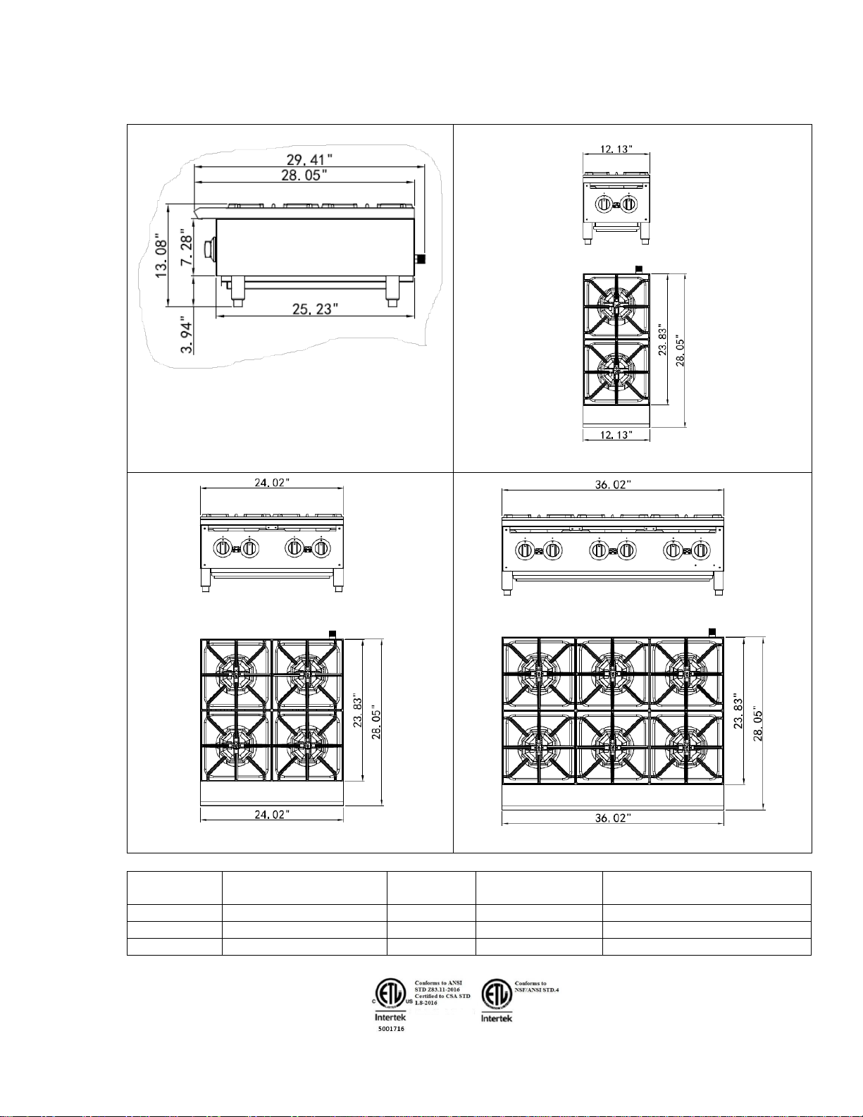
4. Screw legs into (A) the permanently fastened nuts on the four corners of the unit and tighten by hand.
Legs must be installed to adequately provide proper ventilation to the unit. (See Figure 1)
5. Level unit by adjusting the four feet and tighten securely. The adjustable feet have an adjustment of
one inch. Do not slide unit with legs mounted, lift if necessary to move unit.
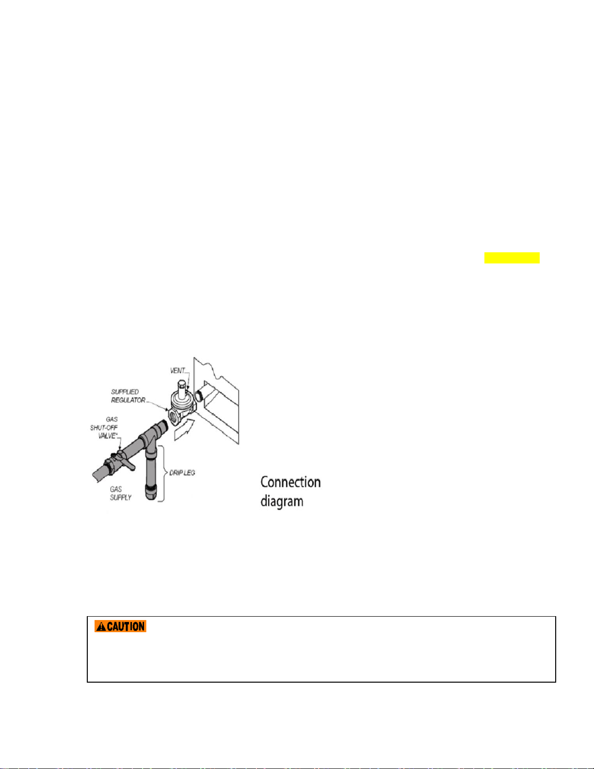
6. The supplied gas pressure regulator is factory set at 4” Natural Gas W.C. or 10” Propane Gas
7. THESE UNITS ARE SUITABLE FOR INSTALLATION ON NON-COMBUSTIBLE SURFACE ONLY.
Noncombustible clearances: 6” sides (152 mm), 6” rear (152 mm), 4” floor (102 mm).
8. Do not obstruct the flow of combustion and ventilation air under the unit by the legs or behind the unit
by the flue. Do not place objects between the bottom of the unit and the counter top.
9. There must be adequate clearance for removal of the front panel. All major parts except the burners
are removable through the front if the gas is disconnected.
10. It may be necessary to adjust the balance of gas volume and air supply to each burner. This must be
done by an authorized service technician.
11. Pipe threading compound must be resistant to the action of liquefied petroleum gas. DO NOT USE
TEFLON TAPE.
The installation of this appliance must conform to local codes, or in the absence of local codes, the
National Fuel Gas Code, ANSI Z223.1/NFPA 54, or the Natural Gas and Propane Installation Code, CSA
B149.1, as applicable.
•The appliance and its individual shut off valve must be disconnected from the gas supply piping
system during any pressure testing of that system at test pressures in excess of ½ PSI (3.5kPa)
DO NOT use an open flame to check for leaks. Check all gas piping for leaks with a soap
and water solution before operating the unit.

6
Owner’s/Installer Manual Rev 20191216 For Warranty Service Call 866-359-7378
•The appliance must be isolated from the gas supply piping system by closing its individual manual
shut off valve during any pressure testing of the gas supply piping system at test pressures equal to
less than ½ PSI (3.5kPa).
Clearance and positioning around the appliance: This appliance must be installed adjacent to non-
combustible surfaces only with a minimum spacing of six (6”) inches from all sides. This appliance must be a
minimum distance of six (6”) inches from another appliance. The appliance must have the supplied four (4”)
inch legs installed and be placed on a non-combustible surface.
Air supply and ventilation: The area in front and around the appliances must be kept clear to avoid any
obstruction of the flow of combustion and ventilation air. Adequate clearance must be maintained at all times
in front and at the sides of the appliance for servicing and proper ventilation.
Pressure Regulator: All commercial cooking equipment must have a pressure regulator on the incoming
service line for safe and efficient operation. The regulator provided for this appliance is adaptable for both
Natural Gas and Liquefied Propane (LP) Gas. A conversion kit with separate instructions is included
explaining this procedure in detail.
Regulator information: ¾” NPT (National Pipe Thread) inlet and outlet; factory adjusted for four (4”) inch
Water Column (WC) Natural Gas standard and may be converted by qualified personnel to be used for
Propane at ten (10”) Water Column pressure.
Prior to connecting the regulator, check the incoming line pressure. The regulator can only withstand a
maximum pressure of ½ PSI (14” WC). If the line pressure is beyond this limit, a step down regulator before
the regulator provided will be required. The arrow forged into the bottom of the regulator body shows gas flow
direction, and should point downstream to the appliance.
Gas Conversion: Conversion from Natural Gas to
Liquefied Propane (LP) or vice versa may only be
performed by the factory or its authorized service
agent. In the case of troubleshooting, ensure that
the correct orifice sizes of the spuds have been
provided.
Natural Gas Orifice #42 dms
Liquefied Propane (LP) Orifice #53 dms
NOTE: The orifice size is marked on the spud.
Gas Connection: The appliance comes fitted with
a ¾” NPT (National Pipe Thread) male adapter for
connection to the pressure regulator.
Maintenance: A qualified service company should check the unit for safe and efficient operation on an annual
basis. Contact the factory representative or local service company to perform maintenance and repairs.
Gas Piping: Gas piping shall be of such size and so installed as to provide a supply of gas sufficient to meet
the full gas input of the appliance. If the appliance is to be connected to existing piping, it shall be checked to
determine if it has adequate capacity. Joint compound (pipe dope) shall be used sparingly and only on the
Any loose dirt or metal particles, which are allowed to enter the gas lines on this appliance,
will damage the valve and affect its operation. When installing this appliance, all pipe and fittings must be
free from any internal contaminates. It is recommended that a “drip leg” be installed in-line before the
regulator.

7
Owner’s/Installer Manual Rev 20191216 For Warranty Service Call 866-359-7378
male threads of the pipe joints. Such compounds must be resistant to the action of Liquefied Propane (LP)
gases.
Manual Shut Off Valve: A manual shut off valve should be installed upstream from the manifold, within four
(4) feet, (1.2M) of the appliance and in a position where it can be reached in the event of an emergency.
Checking For Gas Leaks: Using a gas leak detector or a soapy water solution is recommended for locating
gas leaks. Matches, candle flame, or other sources of ignition shall not be used for this purpose. Check entire
piping system for leaks.
Exhaust Canopy: Cooking appliances inherently create a good deal of heat and smoke and should be
installed under an efficient exhaust hood with flame proof filters. A vertical distance of not less than four (4)
feet shall be provided between the top of the appliance and filters or any other combustible material.
Lighting the Pilot: The manifold units are equipped with standing pilots and each should be lit immediately
after the gas is supplied to the appliance.
1. Before attempting to light pilots, turn off the main gas valve to the appliance and wait five (5) minutes
to clear the gas.
2. Turn off all gas control knobs (E). See figure 1.
3. Turn on main gas valve and light all pilots.
4. The pilot burner must be lit at the end of the tube. Hold an ignition source through the pilot light hole
(D) in the front panel at the pilot tube. When the flame is established remove ignition source.
5. To shut down the appliance, turn off the main gas valve to the appliance.
NOTE: Smoke appearing on initial use of the appliance is normal. This is a result of the rust preventative
coating burning off. This will occur for at least fifteen (15) minutes during the first use or seasoning process.
Pilot Flame Regulation: The pilot flame on the appliance has been factory adjusted. When adjustment is
necessary, adjust the pilot flames as small as possible, but high enough to light the burner immediately when
burner valve is turned to the “HIGH” setting. Access to the pilot flame adjustment screw is obtained by
removing the front panel.
Burner Adjustment: Remove the front panel to gain access. Turn burner valve knob to “HIGH” position.
Slowly decrease mixing ring aperture to give a soft blue flame having luminous tips, then slowly increase
opening to a point where the yellow tips disappear and a hard blue flame is obtained.
COMMISSIONING: Commission of your new Hot Plate is of the utmost importance. Commissioning is the
thorough and methodical testing of the equipment, subsystems, and systems to ensure that the final product
functions properly and safely at the work site. By identifying any potential problems (i.e.: equipment location,
ventilation, local fire/electrical codes, installation, operator training and certification.) prior to equipment being
placed into service, costly outages and potential damages may be avoided.
SAFETY ALWAYS FIRST!
Improper installation, adjustment, alteration, service or maintenance can cause property damage, injury or
death. Read the installation, operating and maintenance instruction thoroughly before installing or
servicing this equipment.
FIRE HAZARD
Do not install or use without 4” legs. Use of this equipment without legs can cause the appliance to
overheat and cause a fire.
FIRE DEATH HAZARD If you smell gas follow the instruction provided by the gas supplier. Do not touch
any electrical switch; do not try to light the burner; do not use a telephone within close proximity.

8
Owner’s/Installer Manual Rev 20191216 For Warranty Service Call 866-359-7378
IMPORTANT SAFEGUARDS & SAFETY INSTRUCTIONS
When using gas cooking equipment, basic safety precautions should always be followed,
including the following:
The Hot Plate outside surfaces may become HOT after use. Use caution when touching the unit.
•Never directly touch the cooking surface while the Hot Plate is on.
•Always turn off the unit when not in use, servicing or adjusting any parts or attachments, and before
cleaning.
•Never leave the Open Burners on overnight.
•Do not operate any equipment with a damaged or leaking gas line, ignitor or valve, or if the unit is
dropped or damaged in any manner. Call for Service.
•The use of attachments not recommended or sold by the manufacture may cause fire, injury or even
death.
•DO NOT USE OUTDOORS. This product is for indoor use only.
•Do not use this equipment for any use other that the use intended by the manufacturer.
•Never use the Open Burners as a heating source.
•The Hot Plate does not contain any user-serviceable parts. Dealer or recommended qualified
technicians should carry out repairs. Do not remove any components or service panels on this
product.
•Never bypass, alter, modify, or attach any unauthorized parts to this equipment. Doing so may create
a hazard and will void warranty.
•We take every care to ensure that all products are safe. Steel cutting procedures used to
manufacture these items result in sharp edges. These sharp edges are removed to the best of our
ability; however, we insist the operator take care when in contact with this piece of equipment.
•Always keep hands, hair, and clothing away from heating source.
•Allow the Hot Plate to cool down after use and before dismantling for cleaning; the unit will be too hot
to handle immediately after use.
•DO NOT USE ICE TO COOL DOWN THE HOT PLATE GRATE. This will cause the grate to warp or
crack and render it unusable.
FIRE, INJURY or DEATH HAZARD
This equipment must be installed by a qualified installer in accordance with all federal, state and local
codes. Failure to install this equipment properly can result in injury or death.
FIRE, INJURY or DEATH HAZARD This appliance is for use in non-combustible location only
FIRE and INJURY or DEATH HAZARD
Injuries or death can occur if this equipment is not used properly. To reduce risk of injury or death:
•Keep the appliance area free and clear from combustibles
•Do not obstruct the flow of combustion and ventilation air
•Do not spray controls or the outside of the appliance with liquids or cleaning agents
•Let hot appliance cool before cleaning or moving
•The appliance should only be used in a flat, level position
•Do not operate unattended

9
Owner’s/Installer Manual Rev 20191216 For Warranty Service Call 866-359-7378
OPERATING INSTRUCTIONS
Operating the Hot Plate –Pilot Lighting Instructions for MANUALLY CONTROLLED OPEN BURNERS
Before operating the Hot Plate, it should be checked to see that it is sitting level. Adjust the feet to level the
Hot Plate. Be sure the catch tray has been properly placed.
The pilot light on the appliance has been set at the factory. Each burner has a pilot light.
1. Make sure all knobs are in the “OFF” position.
2. The main gas valve should be “CLOSED/OFF” for five (5) minutes prior to lighting pilots to clear any
existing gas. (Main gas valve is supplied by others.)
3. Turn on or open the main gas valve to the unit.
4. Light and hold an ignition source (match) at the pilots. When the flame is established, remove the
ignition source. Repeat this step for each burner as each burner has its own individual pilot. The pilot
can be reached through the holes in the front of the unit.
5. Turn each burner knob “ON”. If the burners do not ignite promptly, turn the knobs “OFF”. From the
opening in the front panel, use a screwdriver and turn the pilot valve screw counterclockwise, which
will increase the flame height and repeat step 4.
If the pilot flame appears larger than necessary, turn it down and retest the burner ignition. The pilot
flame should be as small as possible but large enough to guarantee reliable ignition of the burners
when the knobs are turned to “ON”. In the holes located in the front panel are pilot valve adjustments.
Use a screwdriver to turn the valve to adjust the flame height to your desired level.
All burners are lit from constantly burning pilots. Turning the valve to the desired flame height is
all that is required to put the unit into service.
OPERATING INSTRUCTIONS
Igniting the Burner
To ignite the burner, turn knob to the “ON” position, then back off to the desired flame level. The range of
adjustment is virtually infinite between “ON” and “OFF”. The space between the legs at the bottom admits
combustion air. DO NOT BLOCK THIS SPACE.
All burners are lit from constantly burning pilots. Turning the valve to the desired flame height is all that is
required to put the unit into service.
Do not permit fans to blow directly at the unit. Whenever possible, avoid open windows next to the unit’s sides
or back. Avoid wall type fans because they will create air cross-currents within a room.
It is also necessary that sufficient air should be allowed to enter the room to compensate for the amount of air
removed by any ventilation system. Otherwise, a subnormal atmospheric pressure will occur, affecting
operation and causing undesirable working conditions.
A properly designed and installed hood will act as the heart of the ventilation system for the room or area in
which the unit is installed, and will leave the unit independent of changing draft conditions.
NOTE: It may be necessary to adjust the balance of gas, volume, and air supply to each burner. This must be
done by an authorized service technician.

10
Owner’s/Installer Manual Rev 20191216 For Warranty Service Call 866-359-7378
SEASONING THE HOT PLATE TOP GRATE
Be sure to start with a clean cast iron grate. (F) See Fig. 1 Clean off all the packing grease (used to prevent
rust) with a mild soap and warm water. Dry thoroughly. Pour small amount of high quality cooking oil on a
clean cloth (about one ounce (30 cc) per 12” section). Spread the oil (thin coat) over the entire Hot Plate
grate. NOTE: Do not use excessive oil, just a small amount. Allow approximately 20 minutes to soak into the
cast iron grate. The cooking grids are now ready for use.
Note: Each time the Hot Plate is cleaned with soap and WATER, the seasoning is removed, and this process
must be repeated.
OPERATING THE HOT PLATE
Turn the burners on about 15-20 minutes before cooking for preheating. Set the knobs to the desired flame
height or temperature.
Each valve controls the gas flow to the burner to bring that area of the Hot Plate up to the desired
temperature.
Figure 1.
A. LEG. Supports the Equipment
B. ADJUSTABLE FEET. Used to adjust
the level of the equipment.
C. DRIP TRAY. A tray that collects grease
and oil. This tray can be removed for
cleaning
D. PILOT LIGHT ACCESS HOLE. Allows
access to the pilot light.
E. GAS CONTROL KNOB. Used to set or
adjust the temperature of the grilling
surface.
F. CAST IRON GRATE. Cooking Surface
CLEANING INSTRUCTIONS
•DO NOT use any abrasive or flammable cleaning fluids.
•DO NOT hose down, immerse, or pressure wash any part of the Hot Plate, excluding the catch tray.
•NEVER use a scrubber pad (on all exterior surfaces, except the cast iron grates), steel wool or
abrasive material, or cleaners containing chlorine, iodine and ammonia or bromine chemicals as
these will deteriorate the stainless steel and shorten the life of the unit.
IF CLEANING ALL THE HOT PLATE’S SURFACES, THE MAIN GAS VALVE MUST BE
SWITCHED TO THE CLOSED POSITION. AFTER CLEANING, THE GAS LINE CAN BE SWITCHED BACK
TO THE OPEN POSITION. PLEASE FOLLOW THE LIGHTING INSTRUCTION IN THE MANUAL TO
RELIGHT THE HOT PLATE PILOTS AS NEEDED.
F
A
B
D
E
C

11
Owner’s/Installer Manual Rev 20191216 For Warranty Service Call 866-359-7378
Recommended Cleaning
It takes very little time and effort to keep the Hot Plate attractive and performing at top efficiency. Wait until
the Hot Plate is cool after the unit had been turned off. Please follow the cleaning steps below:
PART
REQUIRED ACTION
FREQUENCY
Body
Use a clean cloth and a non-abrasive cleaner to clean the stainless steel
body of the Hot Plate.
Wipe the polished areas with a soft cloth.
Daily
Back and
Side
Splashes
Thoroughly clean. Wipe with clean, with warm soapy water then re-wipe
splashes with a damp cloth.
Daily
Controls
Unit should be turned off when not in use.
It is recommended that the unit be disconnected from the gas supply by
closing the main gas valve. Use a clean cloth to wipe any grease or debris
from the control knobs.
Daily
Hot Plate
Grates
Clean surface with a grill brush or metal scraper.
•Remove cooking grates from the Hot Plate. Place in a sink or
cleaning tub.
•Clean the grate surface thoroughly. If necessary, use a stiff brush.
•Wash with mild soap and warm water.
•Remove all soap and debris thoroughly; wipe with a clean, damp
cloth.
•The cooking grates should then be covered with a thin film of oil to
prevent rusting.
•Clean stainless surfaces with a damp cloth and polish with a soft
dry cloth. To remove discoloration, use a nonabrasive cleaner.
•After each “weekly” cleaning, the Hot Plate must be seasoned
again. If the Hot Plate usage is very high, the “weekly” cleaning
procedures may be done more often than once a week. The use of
ice on the cast iron grates to cool may damage the grates.
Daily
&
Weekly
Catch Tray
Once the unit has cooled, remove the catch tray and discard the waste,
grease, debris, and crumbs. CAUTION: If the catch tray is permitted to fill
too high, grease/debris is likely to accumulate under the unit. This catch
tray/drawer is removed by pulling forward.
USE CAUTION WHEN REMOVING
As Needed

12
Owner’s/Installer Manual Rev 20191216 For Warranty Service Call 866-359-7378
TROUBLESHOOTING
Problem
Possible Cause
Solution
Hot Plate not lighting
Main gas line is closed.
Quick disconnect not inserted all
the way.
Pilot light is not lit.
Cause unknown
Open Valve
Check quick disconnect and
make sure it is fully inserted into
female coupling.
Ignite pilot light.
Call for service.
Flame is too high or too low
Adjustment knob is turned up or
down
Adjust flame with control knob.
Pilot light not staying lit.
Flame is too low
Pilot tube clogged.
Adjust pilot light flame height.
Replace pilot tube. Call for
service.
Strong smell of gas in cooking
area.
Main gas line leak
One or more of the pilot may be
out and burner knob turned on.
Turn off main gas valve. DO NOT
LIGHT FLAME, ignite anything, or
turn/switch on anything electrical.
Call Fire department if needed
and call for service.
Check to see if burners are lit and
pilot is lit. If not, turn off all burner
valves and main gas valve and
wait for excess gas to dissipate.
Reattempt to light pilots after
allowing excess gas to clear.
Cooking surface is heating up
slowly.
Carbon buildup on cast iron
grates.
Cause unknown
Clean cast iron grates.
Call for service.
Gas type of unit needs to be
converted.
Unit ships from the factory
Natural gas. Conversion from
Natural Gas to L.P. is possible for
this unit.
Call for service. This is not
considered a warranty issue. Do
not attempt conversion on your
own.
If problems persist and the assigned solution does not remedy the issue, please call for service.

13
Owner’s/Installer Manual Rev 20191216 For Warranty Service Call 866-359-7378
PARTS
NOTICE
INSTALLATION OF OTHER THAN GENUINE IRON RANGE PARTS WILL VOID THE
WARRANTY ON
THISEQUIPMENT.
The serial plate is located on the right side panel toward the rear. Replacement parts may be ordered either
through an IRON RANGEAuthorized Parts Distributor or an IRON RANGE Authorized Service Agency
When ordering parts, please supply the Model Number, Serial Number, Part Number, and Description.
Ref #
Part #
Description
Ref #
Part #
Description
1
GC10026
Front Panel
9
GC10015
Pressure Regulator
2
GC10027
Burner Knob
10
GC10033
Orifice Connector

14
Owner’s/Installer Manual Rev 20191216 For Warranty Service Call 866-359-7378
3
GC10028
Drip Pan
11
GC10034
Burner Grate 12”
4
GC10008
Adjustable 4” Leg
12
GC10035
Burner (Front & Back)
5
GC10029
Rear Gas Pipe
13
GC10036
Rear Pilot Assembly
6
GC10030
Compression Nut
14
GC10037
Front Pilot Assembly
7
GC10031
Compression Ferrule
15
GC10038
Valve Adapter
8
GC10032
Orifice Hood
THIS PAGE LEFT BLANK INTENTIONALLY

15
Owner’s/Installer Manual Rev 20191216 For Warranty Service Call 866-359-7378
THIS PAGE LEFT BLANK INTENTIONALLY

16
Owner’s/Installer Manual Rev 20191216 For Warranty Service Call 866-359-7378
Commercial Cooking Equipment
GAS HOT PLATE MANUAL
INSTALLATION & OPERATION MANUAL
IRON RANGE COMPANY
360 MELVIN DRIVE
NORTHBROOK IL 60062
800-228-7253
FOR WARRANTY SERVICE CALL:
866-359-7378
A product with the IRON RANGE name incorporates the best in durability and low maintenance.
We all
recognize, however, that replacement parts and occasional professional service may be
necessary
to extend the useful life of this unit. When service is needed, contact an IRON RANGE
Authorized Service
Agency, or your dealer. To avoid confusion, always refer to the Model Number,
Serial Number, and Gas Type of your unit.
This manual suits for next models
2
Table of contents
Popular Stove manuals by other brands

Napoleon
Napoleon GDS60-1N Installation and operation manual

Dimplex
Dimplex EOSM-2007 owner's manual

Cadel
Cadel PRINCE 11 user manual

Hamlet
Hamlet Solution Operating & installation manual

Pevex
Pevex BRIGHTWELL 400 P Installation & operating instructions

US Stove Company
US Stove Company Vogelzang VG5790 Owner's operation and instruction manual