IronStrike WINSLOW PS40 User manual

INSTALLATION AND OPERATION MANUAL
Save These Instructions
For Future Reference
Pellet Stoves
Model Winslow™ (PS40)
Free-Standing
Pellet Stove
P/N 900141-00, Rev. A, 05/2015
A French manual is available upon request. Order P/N 900142-00.
Ce manuel d’installation est disponible en francais, simplement en faire la demande. Numéro de la pièce
900142-00.
This appliance must be properly installed and operated in order to prevent the possibility
of a house fire. Please read this entire manual before installation and use of this pel-
let fuel-burning room heater. Failure to follow these instructions could result in
property damage, bodily injury or even death. Contact your local building or
fire officials to obtain a permit and information on any installation require-
ments and inspection requirements in your area.
WARNING
•
Hot! Do not touch! The glass and surfaces of this appliance will be
hot during operation and will retain heat for a while after shutting off
the appliance. Severe burns may result.
•
Carefully supervise children in the same room as appliance.
•
IHP pellet-burning appliances are designed for use as a supplemental
heater. They are not intended for continuous use as a primary heat
source.
P900141-00
Report No. 14-187
CU
S

2
IMPORTANT SAFETY AND WARNING
INFORMATION
READ THIS MANUAL IN ITS ENTIRETY AND UNDER-
STAND THESE RULES TO FOLLOW FOR SAFETY.
WARNING
Do not attempt to alter or modify the construction of
the appliance or its components. Any modification
or alteration may void the warranty, certification
and listings of this unit.
WARNING
Improper installation, adjustment, alteration, ser-
vice or maintenance can cause injury or property
damage. Refer to this manual. For assistance or
additional information consult a qualified installer,
service agency or the gas supplier.
1. DO NOT CONNECT THIS UNIT TO A CHIMNEY FLUE SERVING
ANOTHER APPLIANCE.
2. Do not connect this appliance to air ducts or any air distribu-
tion system.
3. DO NOT INSTALL A FLUE DAMPER IN THE EXHAUST VENTING
SYSTEM OF THIS UNIT.
4. Do not use class B venting intended for gas appliances as a
chimney or connector pipe on a pellet-fired appliance.
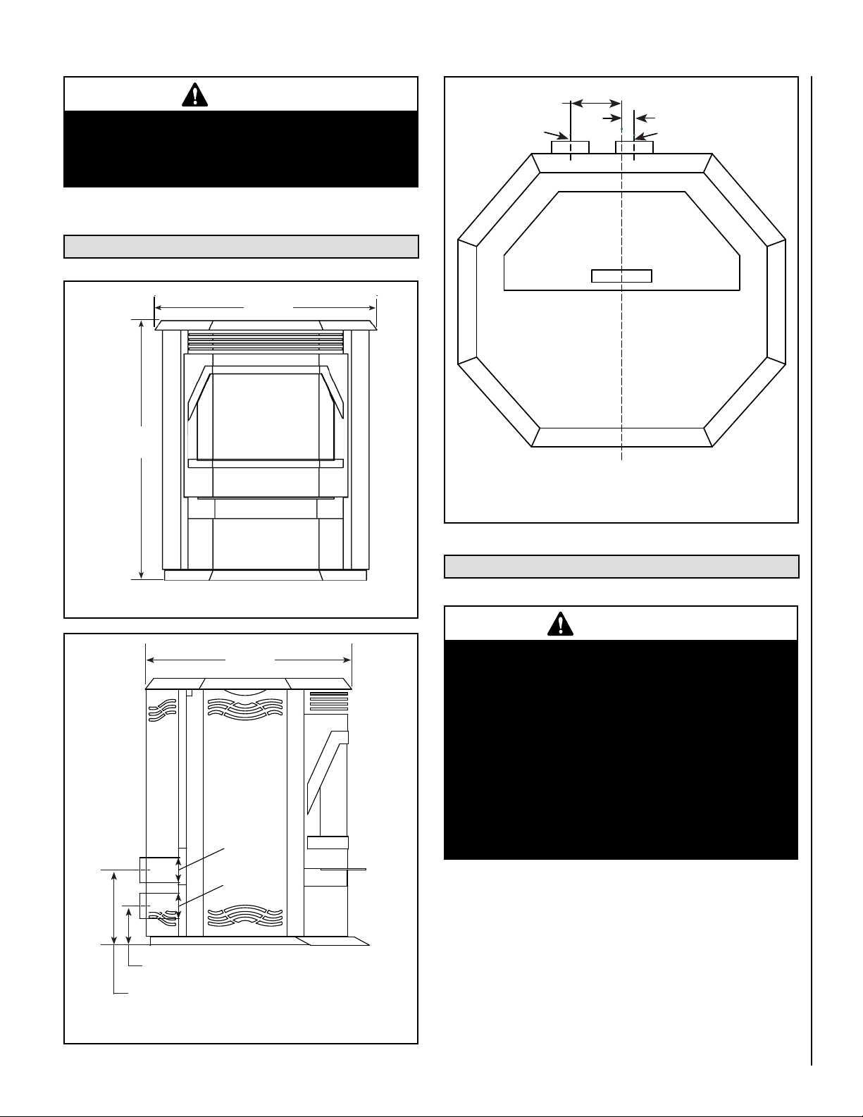
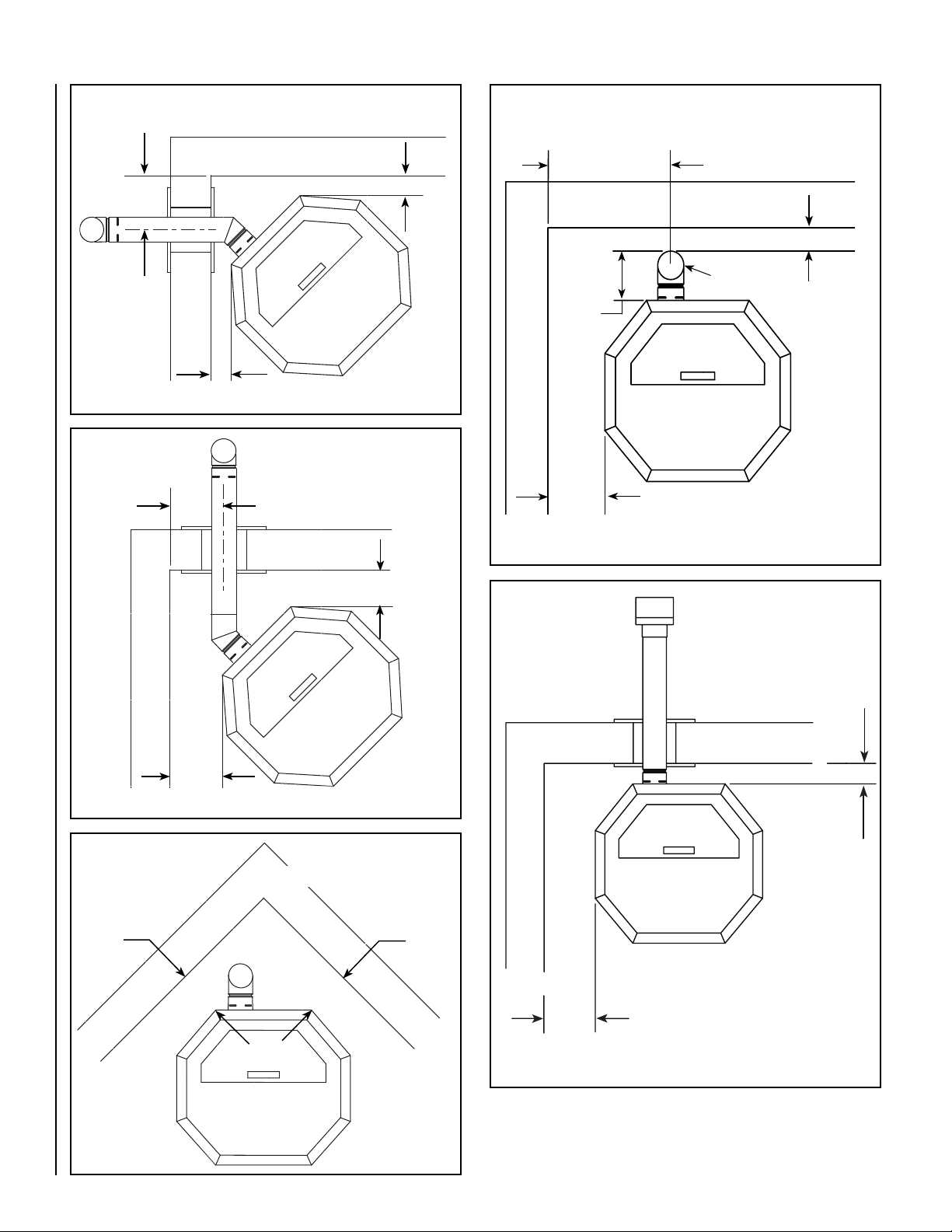
5. The minimum clearances must be maintained for all combus-
tible surfacesand materialsincluding; furniture,carpet, drapes,
clothing, wood, papers, etc. Do not store combustibles within
this clearance space (see Clearances on Pages 8 and 9).
6. INSTALLATION DISCLAIMER - It is imperative that the exhaust
venting system be installed correctly and sealed gas-tight
(not allowing exhaust to leak). Follow the vent manufacturer's
instructions for proper installation. Since IHP has no control
over the installation of your stove, IHP grants no warranty,
implied or stated for the installation or maintenance of your
stove and assumes no responsibility for any consequential
damage(s).
7. Burning any kind of fuel consumes oxygen. If outside air is
not ducted to the appliance, ensure that there is an adequate
source of fresh air available to the room where the appliance
is installed.
8. The appliance will not operate using natural draft, nor without
a power source for the blower and fuel feeding systems.
9. Never use gasoline, gasoline-type lantern fuel, kerosene,
charcoal lighter fluid, or similar liquids to start or “freshen
up” a fire in this heater. Keep all such liquids well away from
the heater while it is in use.
10.The authority having jurisdiction such as municipal build-
ing department, fire department, fire prevention bureau, etc
should be consulted before installation to determine the need
to obtain a permit.
11.APPROVED FUEL: This appliance is designed specifically
for use only with pelletized wood pellets or a mixture of up
to 50% corn mixed with a minimum of 50% pelletized wood
pellets. This mixture of wood pellets and corn should be
evenly pre-mixed before being placed in the units hopper.
This appliance is designed and approved for the burning of
wood residue pellets with up to 2% ash content. This appli-
ance is NOT approved to burn cardboard, nut hulls, cherry
pits, etc. regardless if it is in pellet form. Failure to comply
with this restriction will void all warranties and the safety
listing of the stove. Consult with your IHP dealer for more
information on approved pellet fuels.
12.These appliances are designed as supplemental heaters.
Therefore, it is advisable to have an alternate heat source
when installed in a dwelling.
13.CONTINUOUS OPERATION: When operated correctly, this
appliance cannot be overfired. Continuous operation at a
maximum burn can, however, shorten the life of the electri-
cal components (blowers, motors and electronic controls)
and is not recommended. Typical approved operation would
include running at the low tomid range setting with occasional
running on the maximum setting during the coldest periods
of the winter. DO NOT OVER-FIRE THIS STOVE. Follow all
instructions regarding the proper use of this stove.
14.CAUTION: NEVER PUT FINGERSNEAR AUGER. This appliance
is equipped with a hopper lid switch, which is designed to stop
the auger when the hopper lid is opened. NEVER DISCONNECT
OR BYPASS THIS SWITCH FOR ANY REASON. Pellet fuel is fed
to the Burn-Pot by a screw auger. This auger is driven by a
high torque motor. The auger is capable of causing serious
harm to fingers. Keep pellets in the hopper at all times and
keep fingers away from auger. The auger can start and stop
automatically at any time while the stove is running.
15.CAUTION:HOTWHILE INOPERATION. Anappliance hotenough
to warm your home can severely burn anyone touching it.
Keep children, pets, clothing and furniture away. Contact may
cause skin burns. Do not let children touch the appliance.
Train them to stay a safe distance from the appliance.
16.FLY ASH BUILD-UP: For all wood pellet fuel-burning heaters,
the combustion gases will contain small particles of fly-ash.
This will vary due to the ash content of the fuel being burned.
Over time, the fly-ash will collect in the exhaust venting
system and restrict the flow of the flue gases. The exhaust
venting system should be inspected regularly and cleaned
as necessary.
17.SOOT FORMATION: Incomplete combustion, such as occurs
during startup, shutdown, or incorrect operation of the room
heater will lead to some soot formation which will collect in
the exhaust venting system. A precautionary inspection on
a regular basis is advisable to determine the necessity of
cleaning. The exhaust venting system should be inspected
regularly and cleaned as necessary.
18.DISPOSAL OF ASHES: Ashes should be placed in a steel
container with a tight fitting lid and moved outdoors imme-
diately. The closed container of ashes should be placed on
a noncombustible floor or on the ground, well away from
all combustible materials, pending final disposal. If the
ashes are disposed of by burial in soil or otherwise locally
dispersed, they should be retained in the closed container
until all cinders have been thoroughly cooled.
19.The instructions must be strictly adhered to. Do not use
makeshift methods or compromise in the installation.
20.Do not abuse the door glass by striking, slamming or similar
trauma. Do not operate the stove with the glass removed,
cracked or broken.
21.SAVE THESE INSTRUCTIONS.
22.See the listing label on the appliance.

3
CONGRATULATIONS!
When you purchased your new pellet stove, you joined the ranks of
thousands of individuals whose answer to their home heating needs
reflects their concern for aesthetics, efficiency and our environment.
We extend our continued support to help you achieve the maximum
benefit and enjoyment available from your new pellet stove.
It is our goal at IHP to provide you, our valued customer, with an appli-
ance that will ensure you years of trouble-free warmth and pleasure.
Thank you for selecting a IHP stove as the answer to your home heat-
ing needs.
TABLE OF CONTENTS
Important Safety Warnings ................................................... Page 2
Using This Manual ............................................................... Page 3
Planning Your Installation .................................................... Page 4
Smoke Detector Recommended............................................ Page 4
Carbon Monoxide Monitor Recommended ........................... Page 4
Selecting Your Location ....................................................... Page 5
Negative Pressure Warning................................................... Page 5
Features And Specifications ................................................. Page 6
Stove Dimensions................................................................. Page 7
Clearances To Combustibles ................................................ Page 7
Hearth Protection ................................................................ Page 9
Vent Termination Requirements ........................................... Page 9
Vent Termination Locations ............................................... Page 10
Installation ..................................................................... Page 11-19
Venting .................................................................. Page 11
Fireplace Chimney Installations .............................. Page 12
Vertical Vent ............................................................ Page 13
Mobile Home Installation ....................................... Page 13
Outside Air ............................................................. Page 13
Thermostat ............................................................. Page 13
Door Trim Installation Instructions ......................... Page 14
Door Grill Installation Instruction ........................... Page 16
Brick Panel Installation Instructions ....................... Page 17
Log Set Installation Instructions ............................ Page 19
Operation ....................................................................... Page 20-21
Control Board ......................................................... Page 20
Filling The Hopper .................................................. Page 20
Lighting Your Pellet Stove ...................................... Page 20
Manual Operation ................................................... Page 20
Thermostat Operation ............................................ Page 20
Shut Down ............................................................. Page 21
Paint Curing ........................................................... Page 21
Convection Blower Operation ................................. Page 21
Operating Sounds .................................................. Page 21
Pellet Fuel ...............................................................Page 21
Corn Fuel ................................................................Page 21
Cautions .................................................................Page 21
Cleaning and Maintenance .............................................Page 22-26
Burn-Pot Cleaning ..................................................Page 22
Cleaning Glass ....................................................... Page 22
Ash Drawer Removal And Cleaning .......................Page 22
Inspect Gaskets ..................................................... Page 23
Cleaning Heat Exchanger .......................................Page 23
Cleaning Flue Gas Passageways ............................. Page 23
Cleaning Combustion Blower ................................. Page 24
Cleaning Convection Blower ...................................Page 24
Cleaning Vent Pipe ................................................. Page 24
Cleaning “Proof of Fire” Switch ..............................Page 25
Front Door Removal .............................................. Page 25
Side Door Removal ...............................................Page 25
Back Removal And Lower Cover Plate ................... Page 25
Component Location and Functions...............................Page 26-27
Igniter ................................................................... Page 26
Vacuum Switch ....................................................Page 26
Auger And Auger Motor .......................................Page 26
Over Temperature Snap Switch
(Manual Reset) ................................................Page 26
Proof Of Fire Snap Switch ......................................Page 26
Convection Blower Snap Switch ...........................Page 26
Hopper Lid Switch ................................................Page 26
Draft Adjuster ........................................................Page 27
Wiring Diagram ..................................................... Page 27
Diagnostic Codes .............................................................. Page 28
Troubleshooting ................................................................ Page 28
Replacement Parts List ..................................................... Page 30
Accessories.........................................................................Page 31
Warranty .............................................................................Page 33
Product Reference Information...........................................Page 34
USING THIS MANUAL
Please read and carefully follow all of the instructions found in this
manual. Please pay special attention to the safety instructions provided
in this manual.
PRODUCT IS SUBJECT TO CHANGE WITHOUT NOTICE

4
NOTE: DIAGRAMS & ILLUSTRATIONS ARE NOT TO SCALE.
PLANNING YOUR INSTALLATION
WARNING
Check all local building and safety codes before
installation. The installation instructions and appro-
priate code requirements must be followed exactly
and withoutcompromise. Alterations tothe stoveare
not allowed. Do not connect the stove to a chimney
system serving another stove, appliance, or any air
distribution duct. Failure to follow these instructions
will void the manufacturers warranty.
The installation of this appliance must conform to local codes and appli-
cable state and federal requirements. Familiarity with these requirements
before installation is essential. Important considerations to discuss with
local building officials include:
1. Applicable codes (i.e. Uniform Mechanical Code, State or Regional
Codes).
Electrical codes:
In USA, NEC, ANSI/NFPA 70 – Latest Edition
In Canada, CSA C22.1 – Latest Edition
2. Local amendments
3. Is a permit required - cost. You may wish to contact your insurance
company to ask if they require this.
4. If outside combustion air is required
5. Rooms where the installation is not allowed
Power Supply Requirements
The power cord must be plugged into a standard, 120 volt, 60 Hz grounded
electrical outlet. The power supply cord must be routed to avoid contact
with any of the hot or sharp exterior surface areas of the stove. When
installed in a manufactured home, the appliance must be electrically
grounded to the steel chassis of the manufactured home (see Page 13,
Manufactured Home Requirements for additional requirements). These
requirements must be met unless otherwise specified by state or local
authorities.
Electrical
• Thestoverequires120voltsACforoperation.
• Maximumwattageis700.
• Igniterwattageis400.
• Normaloperatingwattageis300.
Electrical Generator Operation
Your Winslow™ PS40 stove can be powered with a gas driven electrical
generator. However,the generator’selectrical regulator maynot becompat-
ible with the stove’s electronics. The higher the quality of the generator,
the greater the chance that it is compatible with the stove.
Questions To Ask Local Building Official
A correct installation is critical and imperative for reducing fire hazards and
perilous conditions that can arise when wood pellet burning appliances
are improperly installed. The installer must follow all of the manufactur-
ers’ instructions.
WARNING
Electrical grounding instructions: This appliance is
equipped with a three-prong (grounding) plug for
your protection against shock hazard and should
be plugged directly into a properly grounded three-
prong receptacle. Do not cut or remove the ground-
ing prong from this plug. Do not route power cord
under or in front of appliance.
Smoke Detector Recommended
Since there are always several potential sources of fire in any home, we
recommend installing smoke detectors. If possible, install the smoke
detector in a hallway adjacent to the room (to reduce the possibility of
occasional false activation from the heat produced by these appliances).
If your local code requires a smoke detector be installed within the same
room, you must follow the requirements of your local code. Check with
your local building department for requirements in your area.
Carbon Monoxide Monitor Recommended
Carbon Monoxide Poisoning: Early signs of carbon monoxide poison-
ing are similar to the flu with headaches, dizziness and/or nausea. If you
have these signs, obtain fresh air immediately. Some people are more
affected by carbon monoxide than others, including pregnant women,
people with heart or lung disease or anemia, those under the influence
of alcohol, and those at high altitudes.
It is against federal regulations to operate wood heaters in a man-
ner inconsistent with operating instructions in the manual.
Surge Protectors
A surge protector is recommended to ensure the stove’s electrical com-
ponents are not damaged due to a surge in the electrical supply. Only
high quality protectors listed to UL1449 should be used - low quality
protectors do not provide the protection needed.
Installation / Maintenance Standards
National Fire Protection Association – The primary NFPA standard that
refers to installation and maintenance of pellet stoves and venting is
NFPA 211 – Latest Edition: Chimneys, Fireplaces, Vents, and Solid Fuel
appliances.

5
The design of your home and where you place your stove will determine
its value as a source of heat. This type of appliance depends primarily on
air circulation (convection) to disperse its heat, and therefore, a central
location is often best. There are other practical considerations, which
must be considered before a final selection of locations is made. Some
of which includes:
• ExistingChimneys
• PelletFuelStorage
• AestheticConsiderations
• RoofDesign(rafterlocations&roofpitch)
• RoomTrafc
• ProximitytoCombustibles
• ElectricalWiring
SELECTING A LOCATION
CAUTION
The body of these appliances are very heavy. The
use of a heavy duty escalara (stair step hand truck)
is recommended for lifting the appliance body.
NEGATIVE PRESSURE WARNING
This appliance is not designed to be operated in a negative pressure envi-
ronment. In very airtight homes with large kitchen exhaust fans, furnace
cold air returns, fresh air exchange systems and any other air system in
close proximity to the heating appliance may create a negative pressure
in the same room as the heating appliance. This can create dangerous
condition, drawing combustion by-products into the home. Be sure your
home has adequate makeup air to eliminate negative pressures caused
by the above-mentioned sources. Outside air connected to the appliance
probably will not resolve such a problem as the stove is not the source
of negative pressure. IHP accepts no liability for damages resulting from
negative pressures described here.
Ventilation Requirements -
Provide adequate air for combustion. The
fresh air requirements of this appliancemust be met within the space where
it will be installed. Ventilation is essential when using a solid-fuel-burning
heater. In well insulated and weather tight homes, it may inhibit the rate
the exhaust flows through the venting system (caused by a shortage of
air in the home). The lack of air is caused by many common household
appliances which exhaust air from the home (such as a furnace, heat
pump, air conditioner, clothes dryer, exhaust fans, fireplaces, and other
fuel burning appliances). Also, the combustion process of this heater
uses oxygen from inside the dwelling. If the available fresh air delivery
in the dwelling is insufficient to support the demands of these appli-
ances, problems can result (i.e. excessive negative pressure will result
in performance problems. To correct this problem it may help to open
a window (preferably on the windward side of the house) or install an
outside combustion air duct to the appliance.

6
FEATURES AND SPECIFICATIONS
Installation Options
• ResidentialandCommercial
• Ventedverticalandhorizontal(seeventinginstructions)
• Manufacturedhomeandmobilehome
• Thermostatormanualoperation
• Bedrooms
Heating
•Max.feedrateis4.7pounds/houror39,500BTU/hour
•Min.feedrateis1.8pounds/houror15,120BTU/hour
Venting
This stove is approved for venting with Type L and Type PL pellet vent
pipe listed to UL 641 and ULC S609. The flue collar on the stove accepts
3” diameter pipe.
The combustion air for this stove is drawn through a pipe at the lower
rear of the stove. For mobile home installations a 3” ID flex line or pipe
must be attached to the stove’s air intake to draw air from outside the
house. The vent pipe can be installed vertically or horizontally (see Venting
section for recommended installations).
NOTE: When installing this stove at altitudes of 4000 feet and above, we
suggest the use of 4” pellet vent.
Thermostat
This stove can be operated manually or with a thermostat.
Lighting
This stove is equipped with an electric self igniter for ease of ignition.
Weight - 305 pounds
Hopper Capacity - 60 pounds
Listing information
The Winslow™ PS40 stove is safety tested and listed with the following
agencies;
• PFSCorporationtoASTME1509
• USEPAListofApprovedWoodHeatingAppliances
• ListofColoradoApprovedPelletStoves
Appearance Choices
The Winslow PS40 stove can be ordered with the following door trims
and grills, log set and brick panel options:
Door Trim Kits Grill Kits
Black .......................79038 Black............................ 79000
Gold .......................79034 Gold............................. 79001
Nickel .....................79037 Nickel .......................... 79002
Brushed Nickel........79035 Brushed Nickel ............ 79022
Black Nickel ............79036 Black Nickel................. 79039
Log Set .............................. H5142
Brick Panel Kit ..................... 79030
Wood Pellet Specifications
This appliance has been designed to burn wood residue pellets with up
to 2% ash content. Dirty fuel will adversely affect the performance of the
stove. Any questions regarding pellet fuel can be answered at the Pellet
Fuels Institute (PFI), pelletheat.org.
Pellet fuel is made from sawdust and scrap wood from many different
species of wood. Pellets are either 1/4” or 5/16” in diameter and vary in
length. The PS40 stove will burn either diameter pellets. Pellets made
from hardwoods contain more ash than those made from softwoods.
Minerals from ash and sand in the pellets form clinkers under the extreme
temperatures in the Burn-Pot. Try burning various brands of pellets until
you find one that burns with minimum ash and clinkers. Once you find
a pellet brand that burns well, continue using this brand. High ash fuel
increases the frequency of stove cleaning. Fuel with an excessive moisture
content may jam the auger assembly.
Clinkering - Silica (or sand) in the fuel, along with other impurities, can
cause clinkering. A clinker is a hard mass of silica formed in the burning
process. Clinkering is a function of the fuel, (not the stove), but adversely
affects the performance of the stove by blocking off the air passages in
the Burn-Pot. Even P.F.I. approved pellet fuel may tend to clinker. See
Maintenance for more information on cleaning.
Pellet Fuel Storage -
• Store your wood pellets in a dry place to prevent them from absorb-
ing excess moisture.
• Do Not store your wood pellets within the clearance zone of the
stove.
• Do Not store your wood pellets in a place that would block access
to refueling the hopper.
Wood pellets manufactured to the pellet fuels institute (P.F.I.) certification
standard are available in two grades, Standard and Premium. The primary
difference between the two is the ash content of the pellets.
The P.F.I. specification for standard grade and premium grade residential
and commercial pellet fuel is as follows:
• CHLORIDES (Salt): Less than 300 p.p.m. to avoid stove and vent
rusting.
• BULKDENSITY:38to40lb./Cu.Ft.minimum
• MOISTURECONTENT:8%to10%maximum
• ASHCONTENT:<2%maximum(standardgrade)<1%maximum
(premium grade)
• FINES:0.5%to1%maximumthrougha1/8”screen
• BTUCONTENT:Thereareanumberofvariationsinpelletfuelsthatare
not included in PFI standards. For example, BTU (heat value) content
may range from just under 8,000 to almost 9,000 Btu, depending upon
species and region of the country and other variables.
Corn Fuel Specifications
Use only clean-shelled corn with a moisture content less than 15% and
approximate fuel value of 7000 BTU/lb (16,200 kJ/kg). Do not attempt
to burn corn with higher moisture content or burn lesser grade fuels.
Do not burn other types of agricultural pellets or by-products (alfalfa,
cherry pits, olive pits, nut shells, etc.) as they are not permitted to be
burned in these appliances.
Shelled corn can be burned in the PS40 pellet stove when it is mixed with
wood pellet fuel. The mixture can contain a maximum of 50 percent corn.
Burning corn may create more ash than wood pellets and may necessitate
the need to clean the Burn-Pot and glass more frequently.
Store corn in a tight container and use methods to ensure the corn does
not become rain soaked or absorb moisture from damp or wet sources.
This will also prevent rodents from becoming a problem. Do not store
corn within stove installation clearances.
NOTES:
• Cornwithexcessivegraindustmustbescreened,bysiftingwith
3/16"meshscreening.Largepiecesofcobmayplugtheauger.
• Whenchanging fromburningall woodpelletsto burningacorn
andwoodpelletmix,thedraftadjustermayneedtobeadjustedto
achievepropercombustion.
FUEL
CAUTION
The use of unapproved, dirty, wet and / or high salt
content fuel will void the warranty!
This stove is designed to burn wood pellet fuel. In addition, a corn/wood
pellet mixture, with a maximum of 50 percent corn can be burned. Burning
any other fuel that is not approved for use with this appliance will void
the appliance warranty. IMPORTANT: The corn/wood mix needs to be
mixed evenly before being put in the pellet stove hopper.

7
NOTE: DIAGRAMS & ILLUSTRATIONS ARE NOT TO SCALE.
STOVE DIMENSIONS
CLEARANCES TO COMBUSTIBLES
8
Side ViewFront View
26-1/4”
(667mm)
Front View
31”
(787mm)
The center of the flue is 8-
7/8” above the surface upon
which the stove rests.
Figure1
Figure2A
INSTALL VENT AT CLEARANCES SPECIFIED BY THE VENT
MANUFACTURER.
IMPORTANT
• Minimum clearances specied may not allow
foreaseofoperationandmaintenance(please
takethisintoaccountwhenplanningtheinstal-
lation).Ifinstalledtotheminimumclearances,
removaloftheappliancemaybenecessaryfor
servicing.
• Recommended clearance zone from the front
oftheappliancetocombustiblesis4feetmini-
mum.
• Clearances to combustibles for the appliance
canonlybereducedbymeansapprovedbythe
regulatoryauthority.
4-5/8” (118mm)
C/L
C/L
23-1/4”
(591mm)
8-7/8” (225mm)
Exhaust
3” (76mm)
O.D.
Air Intake
3” (76mm)
O.D.
Exhaust Air Intake
4-1/8” (105mm)
C/L
Figure2B
1” (25mm)
Side View
Top View
WARNING
Do not burn treated seed corn! Seed corn is treated
with chemical pesticides that are harmful or fatal
if swallowed. Burning treated corn will void your
warranty!

8
NOTE: DIAGRAMS & ILLUSTRATIONS ARE NOT TO SCALE.
Figure4
Figure3
Parallel Installations - Clearance to Combustibles
Vertical Venting
Horizontal Venting
Clearance to Combustibles
5-7/8”
(149mm) 5-7/8”
(149mm)
17-1/4”
(423mm)
6”
(152mm)
8”
(203mm)
8”
(203mm)
3” (76mm)
Top Vent
Figure5
Figure6
Figure7
Corner Installations - Clearance to Combustibles
Left Wall Horizontal Venting
* Refer to pipe Manufacturer's installation instructions for minimum
pipe clearances.
3" (76mm)*
8”
(203mm)
3” (76mm)
3”
(76mm)
6-3/4”
(172mm)
7”
(178mm)
Corner Installations
Clearance to Combustibles
Right Wall Horizontal Venting
7”
(178mm)
Corner Installations
Clearance to Combustibles
Vertical Venting

9
NOTE: DIAGRAMS & ILLUSTRATIONS ARE NOT TO SCALE.
HEARTH PROTECTION
VENT TERMINATION REQUIREMENTS
This appliance requires noncombustible floor protection (the hearth pad
or alternate floor protection material does not require a thermal rating).
A noncombustible floor protector must fully cover the area beneath the
appliance as illustrated in Figure9.
If the floor protection is to be stone, tile, brick, etc., it must be mortared
or grouted to form a continuous noncombustible surface. In Canada, if a
chimney connector / venting extends horizontally over the floor, protec-
tion must also cover the floor under the connector / venting and at least
2” (51 mm) to either side (recommended but not required in the US).
Minimum Size Hearth Protection
1. Do not terminate the vent in any enclosed or semi-enclosed areas
such as a carport, garage, attic, crawlspace, narrow walkway, closely
fenced area, under a sundeck or porch, or any location that can build
up a concentration of fumes such as stairwells, covered breezeway,
etc.
2. Vent surfaces can become hot enough to cause burns if touched.
Non-combustible shielding or guards may be required.
3. Termination must exhaust above the inlet elevation. It is recommended
that at least five feet of vertical pipe be installed outside when the
stove is vented directly through a wall. This will create a natural draft
to prevent the possibility of smoke or odor during appliance shut
down or power failure and avoid exposing people or shrubs to high
temperatures.
4. The vent should terminate no less than four feet below, no less than
four feet horizontally from and no less than one foot above doors and
windows, or gravity/ventilation air inlets into the building.
5. The distance from the bottom of termination to grade is 12” (305 mm)
minimum unless otherwise specified by the vent manufacturer. The
distance between the bottom of the termination and a public walkway
should be a minimum of seven feet.
6. Locate the vent termination at least two feet away from combustible
materials such as shrubs, plants, grass, fences, roof overhangs and
adjacent buildings.
Stove Base
Firebox Front Edge
Hearth Protection
Outline of Stove Base
3-7/8”
(98mm)
6”
(152mm)
6”
(152mm)
6”
(152mm)
3-7/8”
(98mm)
9-5/8”
(245mm)
14-1/4”
(362mm)
9-5/8”
(245mm)
10-3/4”
(273mm)
8-7/8”
(225mm)
8-7/8”
(213mm)
7-9/16”
(192mm)
18-3/8”
(467mm)
7-9/16”
(192mm)
33-1/2”
(851mm)
28”
(711mm)
Figure9
Figure10
Alcove Installations
Minimum alcove height is 41” (1041 mm), minimum width is 42-1/4”
(1073 mm) and maximum depth is 48” (1219 mm). Note, it is quite dif-
ficult to load pellets into the hopper when installed in an alcove only 41”
(1041 mm) high. For alcove wall clearances see parallel clearances below.
48”
(1219mm)
Figure8
41”
(1041mm)
42-1/4”
(1073mm)

10
NOTE: DIAGRAMS & ILLUSTRATIONS ARE NOT TO SCALE.
VENT TERMINATION LOCATIONS
A = Refer to vent manufacturer's installation instructions for the re-
quired clearance above grade, veranda, porch, deck, or balcony.
B = Clearance to window or door that may be opened (min. 12”/30cm
above - 48”/1.2m below and to the side)
C = Clearance to permanently closed window *(min. 12”/30cm)
D = Vertical clearance to ventilated soffit located above the terminal
within a horizontal distance of *(min. 24”/60cm) from the centerline
of the terminal (min. 22”/55cm) check with local code.
E = Clearance to unventilated soffit *(min. 12”/30cm)
F = Clearance to outside corner *(min. 12”/30cm)
G = Clearance to inside corner *(min. 12”/30cm)
H = Not to be installed above a meter/regulator assembly within *(min.
36”/90cm) horizontally from the centerline of the regulator.
J = Clearance to service regulator vent outlet *(min. 72”/1.8m)
K= Clearancetonon-mechanical air supplyinlet to buildingor the
combustion air inlet to any other appliance *(min. 48”/1.2m)
L = Clearance to a mechanical air supply inlet *(min. 120”/3.1m)
M = **Clearance above paved sidewalk or a paved driveway located on
public property *(min. 84”/2.1m)
N = ***Clearance under veranda, porch, deck, or balcony (min.
12”/30cm)
NOTES:
* Local codes or regulations may require different clearances.
** A vent shall not terminate directly above a sidewalk or paved
driveway which is located between two single family dwellings
and serves both dwellings.
*** Only permitted if veranda, porch, deck, or balcony is fully open on
a minimum of two sides beneath the floor.
Vent Terminal
Area Where Terminal Is Not Permitted
(From Eave)
Vertical Terminal
Vertical Terminal
Fixed Closed
Able To Open
A
A
B
B
B
B
C
D
E
F
G
H
J
K
L
M
N
24”
(610mm)
B
Air Supply Inlet
24”
(610mm)
Figure11
USA - 1' Min.
CANADA - 3' Min.
USA - 1' Min.
CANADA - 3' Min.
NOTE: Vent requirements are in
accordance with NFPA 211 and CAN/
CSA-B365-Mstandards

11
NOTE: DIAGRAMS & ILLUSTRATIONS ARE NOT TO SCALE.
Venting
This stove is approved for venting with Type L and Type PL pellet vent
pipe listed to UL 641 and ULC S609. Single wall pipe cannot be used with
this pellet stove. The stove’s flue collar is 3” in diameter. An approved
wall thimble or approved ceiling firestop must be used when the pellet
pipe passes through a combustible wall or ceiling. The stove’s combus-
tion blower pressurizes and pushes flue gases out the pellet pipe. As a
result, all pipe joints should be locked together or screwed with three
screws if the pipe does not have a locking system and sealed with high
temperature silicone. The pipe should be siliconed and fastened with
three screws to the stove’s flue collar.
In Canada, where the venting may pass through a wall, or partition of
combustible materials, the installation shall conform to CAN/CSA-B365.
When installing the wall thimble and other venting components, follow
the vent manufacturers instructions. Maintain an effective vapor barrier
at the location where the chimney or other component penetrates to the
exterior of the structure.
The longer the run of pipe and the more elbows used, the greater the
resistance to the flow of flue gases. Four inch diameter pellet pipe is
recommended for pipe runs greater than 15 feet or when a number of
elbows are used.
To aid in cleaning, whenever possible, the venting system should include
a tee with clean out attached to the flue collar on the stove. Do not install
back to back elbows right off the back of the stove in any installation.
DO NOT INSTALL A FLUE DAMPER IN THE EXHAUST VENTING
SYSTEM OF THIS UNIT. DO NOT CONNECT THIS UNIT TO A
CHIMNEY FLUE SERVING ANOTHER APPLIANCE.
Horizontal installations that terminate without any vertical sections
of pipe are approved; however, wind may direct flue gases toward the
house causing discoloring problems. For this reason, horizontal and up
5 feet or horizontal and through the eave installations are recommended.
Wood Stove
Pipe Retrofit
The Winslow™ PS40
stove stove can be
vented into existing
6” or 8” diameter
wood stove pipe.
45° 90°
Horizontal and UP 5’
Horizontal and Up
Through the Eave
1 foot
minimum
Horizontal
Figure12
Figure15
Figure14
Figure 13
INSTALLATION

12
NOTE: DIAGRAMS & ILLUSTRATIONS ARE NOT TO SCALE.
Masonry Chimney
When venting into a masonry chimney, the pellet pipe can terminate just
inside the chimney. However, it is recommended to run the pellet pipe
to the top of the chimney.
Fireplace
When venting into a fireplace chimney, the pellet pipe can terminate just
above the damper. However, it is recommended to run the pellet pipe to
the top of the chimney.
Figure18
Figure16
Figure17 Figure19
Optional
Clean-Out
Access Door

13
NOTE: DIAGRAMS & ILLUSTRATIONS ARE NOT TO SCALE.
Mobile Home Installations
In addition to the standard installation instructions, the following instruc-
tions may be required by local, state or federal building codes.
• InstallationshouldbeinaccordancewiththeManufacturedHomeand
Safety Standard (HUD), CFR 3280, Part 24.
• Thestove mustbe permanentlyboltedtothefloor using 1/4" diameter lag
screws. The screws can be inserted through the holes in the pedestal
located behind the side doors. The lag screws must be an adequate
length to extend through the hearth pad and into the floor. A minimum
of two lag screws must be used.
• Connecting the Winslow™ PS40 stove to outside combustion air is
required in manufactured home installations and when required by
local building codes. An outside air inlet must be provided for com-
bustion and be unrestricted while unit is in use. Use a galvanized or
stainless steel pipe for the duct (the outside air inlet on the stove is 3”
diameter). The air intake on the exterior of the home should always be
located a minimum of 18” below the flue termination. The Inlet shall
remain free of obstruction while unit is in operation and constructed
in a manner so as to prevent material from dropping into the inlet or
into the area beneath the dwelling. The inlet shall also have a screen
with openings not larger than 1/4" to prevent rodents from entering.
• The stove must be permanently electrically grounded to the steel
chassis of the manufactured home using a 8 GA copper wire and a
serrated or star washer (to penetrate paint or protective coating to
ensure grounding). The location selected for ground attachment to the
stove must be dedicated for this purpose. Grounding must comply
with NFPA-70-latest edition standards, CSA C22.1-latest edition in
Canada, as well as any local codes.
Vertical
If the length of pipe exceeds 15 feet, 4 inch pipe rather than 3 inch vent
pipe should be used.
WARNING: DO NOT INSTALL THIS STOVE IN A SLEEPING ROOM
IN A MANUFACTURED HOME.
CAUTION: THE STRUCTURAL INTEGRITY OF THE MANUFAC-
TURED HOME FLOOR, WALL AND CEILING/ROOF MUST BE
MAINTAINED.
Outside Air Installations
Connecting the Winslow PS40 stove to outside combustion air is required
in manufactured home installations and when required by local building
codes. The stove’s air intake will accept 3” ID pipe to accommodate outside
air installations. The air intake on the exterior of the home should always
be located a minimum of 18” below the flue termination and must remain
free of obstruction. The inlet must also have a screen with openings not
larger than 1/4” to prevent rodents from entering.
Thermostat installation
The Winslow PS40 stove can be operated manually or by thermostat. The
stove comes from the factory wired to operate manually - see control
board operation on Page20. A low voltage thermostat can be installed
on the stove. To install the thermostat:
1) Unplug the stove from the electrical outlet. Open the right side door
and lift out the control board from its retaining brackets. Locate the
light green wiring block at the bottom back of the board (see Figure
21), loosen the two screws B at the back of the block and remove the
U shaped jumper wire A protruding from the block.
2) Insert a wire from the thermostat into one of the slots from which
the jumper wire was removed. Repeat this process for the other
thermostat wire.
Retain the jumper wire for future reinstallation. See Page20 for thermostat
operation instructions.
IMPORTANTNOTE:Installthethermostatperthemanufacturers
instructions,providedwiththethermostat.Failuretofollow
manufacturersinstructionscouldresultinamalfunction.Pay
specialattentiontothethermostatlocationrequirements.Ifthe
locationrequirementsarenotadheredtotheappliance,erratic
operationorfailuremayoccur.
Do not mount the thermostat where it may be affected by:
• Radiant heat from the stove, replaces, sun or other heat
sources.
• Drafts or dead spots behind doors or in corners.
• Hot or cold air from ducts.
Listed Pellet Pipe
Ceiling Firestop
Storm Collar
Roof Flashing
Rain Cap
Outside Air Pipe
Figure20
Figure21
WiringBlock
B
A
Rear View of Control Board
A = Jumper Wire
B = Screws
A B
Rear View of Control Board
Wiring Block

14
NOTE: DIAGRAMS & ILLUSTRATIONS ARE NOT TO SCALE.
Door Trim Installation Instructions
(ref.form#775274M)
Parts List (A):
Qty
(2) Trim Pieces (Gold, Nickel, Brushed Nickel or
Black Nickel)
(6) #10 nuts
(6) #10 washers
Tools Needed:
Qty
(1) 3/8” nut driver or socket wrench
CAUTION: Always ensure that plated surfaces are clean and
free of fingerprints before lighting stove. Fingerprints will leave
permanent blemishes if left on plated surface when lit. When
installation is complete, the trim should be gently cleaned
with soft cloth and either alcohol or glass cleaner. Do not
overtighten nuts, overtightening can create visible dimples on
the plated surface.
To install Door Trim:
1. Remove the trim pieces and hardware from its packaging and ensure
that all pieces are present before beginning installation. Take care not
to scratch finished surfaces.
2. Open right and left side door. The side doors swivel open towards the
back of the stove. See Figure24.
3. Open front door. Put trim in place by inserting trim studs into the cor-
responding holes in the door (Figures22and25). The top piece of
trim will only fit in one direction, but the bottom piece can be installed
incorrectly. When placing the bottom piece of trim, make sure there
is a 9/16” gap between the top of the trim piece and the glass in the
door (see Figure26).
Trim stud
Door Handle
Holes for trim studs
Trim Screws
#10 washers
Trim Pieces
Top of Trim
(A)
Pellet Stove Door
Trim Pieces
Figure23
Figure24
Figure25
Figure26
Figure22
Pellet Stove Door
Trim Pieces

15
NOTE: DIAGRAMS & ILLUSTRATIONS ARE NOT TO SCALE.
4. Place one washer on each stud. Using a 3/8” nut driver, snug up the
nuts on each piece of trim. Do not finish tightening the nuts yet. See
Figure27.
5. There should be approximately a 7/8” (22 mm) gap between the top edge
of the upper trim and the top edge of the door and a 1-1/2” (38 mm) gap
between the bottom trim to the bottom of the door. Visually inspect the
alignment of the trim and adjust if necessary. See Figure28.
6. Finish tightening nuts. CAUTION - DO NOT OVER-TIGHTEN NUTS,
DIMPLING OF THE TRIM WILL OCCUR!!!
Figure28
Figure27

16
NOTE: DIAGRAMS & ILLUSTRATIONS ARE NOT TO SCALE.
Door Grill Installation Instructions
(ref.form#775273M)
Parts Needed:
Qty
(4) Button Head Screws (already in place in stove)
Tools Required:
Qty
(1) 1/8” allen wrench
To install the Grill:
1. Remove the four button head screws from body of the stove with a
1/8” allen wrench. See Figure29.
2. Pull the scraper rod out, rotate the grill vertically, (with the notch to
the left) and slide the grill over the scraper rod (slide the rod between
the third and fourth bar). See Figure30.
3. Rotate the grill back to the horizontal position and re-install the four
button head screws through the two holes at each end of the grill and
into the stove body. See Figure31.
Figure30
Figure31
Figure32
Figure29
Rotate Grill Back To Horizontal Position
Slider Rod
Between 3rd and 4th Bar
Notch
Re-install Button Head Screws
Button Head Screw

17
NOTE: DIAGRAMS & ILLUSTRATIONS ARE NOT TO SCALE.
NOTE:Thebrickpanelcomespre-paintedwithMetallicBlackpaint.
Thebrickpanelmaybepaintedwithanycolorofhigh-temppaint(paint
maydiscolorwithuse).
1. Remove the front door of the pellet stove. To remove the front door,
open the two side panels, swing open the front door and lift it up
and off of its hinges. Remove the optional log set, if present and the
Burn-Pot.
Brick Panel Installation
Option: Part #79030
Kit Contents:
- Brick Panel (A)
- 4 Tap Tights (B)
Tools Required:
- Drill (90° drill recommended)
- #18 drill bit
- 5/32 allen wrench
Figure34
2. Remove all pellets and ash from the firebox to ensure a proper fit for
the brick panel.
3. Insert the brick panel, top first, as shown in Figure35. The two cut
out corners should be at the bottom.
4. Make sure that the brick panel is centered, with equal space on either
side of the auger tube. While holding the panel in place, use the drill
with a #18 drill bit to drill out the four holes in the back of the firebox,
as shown in Figure36.
Figure35
Figure36
A
B
A
B
Figure33

18
NOTE: DIAGRAMS & ILLUSTRATIONS ARE NOT TO SCALE.
5. Screw in the four tap tights, included with this kit, using a 5/32 allen
wrench.
6. Replace the Burn-Pot and check that it is firmly in place (if you can
rotate the Burn-Pot it is not installed correctly). If present, install
the optional log set according to the log set installation instructions
(included with your log set).
7. Re-hang the door by reversing the instructions in step 1.
Figure37

19
NOTE: DIAGRAMS & ILLUSTRATIONS ARE NOT TO SCALE.
Log Set Installation Instructions
(ref.form#775275M)
Kit Contents
(refer to Figure38)
1 ea. Left Log (A)
1 ea. Right Log (B)
1 ea. Front Log (C)
2 ea. Log Support Brackets (D)
1 ea. Instruction Sheet
Tools Required
None
CAUTION: The logs can be damaged if they are not handled
with care!
To Install the log set:
1. Remove the two log support brackets (D) from the box and bend the
ends of the brackets 90 degrees at the bend lines. See Figures39and
40.
2. One bracket goes into the left corner and the other into the right corner
of the firebox. Rotate the brackets (D) so they are placed as shown
in Figure40. The bracket fits between the back of the firebox and the
air wash at the front of the insert.
3. Remove the ceramic logs from the box and carefully unwrap them.
Position each back log (A and B in Figure41)in their proper place,
one on each side against the back of the firebox.
4. The front log should face the front of the firebox with the wood grain
showing. It should rest on the other two back logs. See Figure41
for assembled log set.
Cat. No. Model Description
H 5142 P40LOG Winslow Log Set
bend lines
Figure39-LogSupportBrackets
D
Bracket correctly placed
D
Figure40-LogSupportBracket
Figure41-CompletedInstallation
AB
C
Figure38-Kitcontents
AB
C
D

20
NOTE: DIAGRAMS & ILLUSTRATIONS ARE NOT TO SCALE.
OPERATION
Control Board
The control board regulates all functions of the stove. The following is a
list of the board’s components:
• Feeding light - lights up when the auger is feeding pellets into the
Burn-Pot.
• Ready Light - lights up when stove is ready to operate.
Igniting Light - lights up when the stove is in the ignition sequence.
• Start Button - is pushed to start the ignition sequence after the heat
selector knob is turned from off.
HeatSelectorKnob-isturnedtoofftoshutthestoveofforturnedto
a setting from 1 to high to regulate the burn rate.
• Igniter Fuse - six amp fuse to protect igniter heating element.
• Control Fuse - three amp fuse to protect the control board.
Lighting
1. Turn the heat selector knob (see Figure42)to the heat level desired - 1
through high - and the ready light will turn green.
2. Push the start button and the ignite and feeding lights will come on
and the lighting sequence will begin. For about the next 15 minutes
the stove will feed pellets cyclically into the Burn-Pot, the combustion
blower will come on and the igniter will heat up. During this sequence,
some smoke in the firebox is to be expected. After the igniting sequence
is complete, the stove will begin burning at the level indicated by the
heat selector knob.
NOTE: Upon the stove’s initial light up, or if the stove has previously run
out of pellets, the auger feed tube may not contain a sufficient number of
pellets to allow the stove to continue burning after the ignition sequence.
It may be necessary to push the start button a second time to run the start
sequence again. It is important to always empty (when cool) the Burn-Pot
of pellets before pushing the start button a second time.
Filling the Hopper
The hopper can be accessed by lifting the lid at the rear of the top of the
stove. The hopper will hold 60 pounds of pellets. Remove any contents
from the hopper and fill with pellets as follows:
To fill the hopper when stove is off:
1. Lift the hopper lid to its full opened position.
2. Fill the hopper with pellets.
3. Check to make sure there are no remaining pellets on top of the
hopper that may prevent the hopper lid from fully closing.
4. Close Hopper lid.
To fill the hopper when stove is in operation:
1. Repeat steps 1 thru 4 above.
2. When finished, check the burn pot to assure there is substantial
combustion taking place to light the pellets once the pellets start
feeding after refueling.
3. If combustion is not present in the burn pot then the unit will need
to be restarted. This can be done by turning the heat setting dial to
off and back to the desired heat setting 1 thru 5. You will then have
to press the start button to initiate ignition.
CAUTION: Failure to confirm pellets in the Burn Pot remain
burning after re-fueling may result in smoke escaping from the
unit. Smoke escaping the unit can also be a result of ignition
of the unit with excessive pellets located inside the burn pot.
Figure42
Manual Operation
After the stove is burning (see lighting above), the heat selector knob
controls the pellet burn rate and the stove’s heat output. Turning the
knob to setting 1 allows the stove to burn about 1.8 pounds of pellets
per hour - about 8,500 BTUs per hour. Turning the knob to high allows
the stove to burn 4.7 pounds of pellets per hour - about 39,000 BTUs per
hour. Once set, the stove will continue to burn at this rate until shut off.
Thermostat Operation
This stove will operate with a low voltage thermostat. See Page 13 for
instructions on installing the thermostat. Once installed, the thermostat
will control the operation of the stove. Important: When connected to a
thermostat, it is necessary to push the ignite button for the initial burn,
when the electrical flow to the stove is interrupted, if the selector knob
is turned to off (and then back on), or if the stove runs out of pellets and
therefore shuts off. After the initial ignition sequence, when the thermostat
calls for heat (the room temperature is less than the temperature set on
the thermostat) and the heat selector knob is not in the off position, the
stove will burn at the heat selector knob setting. The higher the setting,
the quicker the room will heat up. Once the thermostat no longer calls for
heat (the room is up to the desired temperature), the stove will continue
to burn for one additional hour at the lowest setting. If the thermostat
does not call for heat again during that hour, the stove will shut off. Dur-
ing that hour, if the thermostat calls for heat again, the stove will again
burn at the heat selector knob setting until the thermostat no longer
calls for heat. If the stove shuts off after that hour it will relight when the
thermostat calls for heat.
WARNING
• Never empty pellets from the Burn-Pot into the hopper.
Pellets that may appear to be cool may retain enough
heat to ignite other pellets resulting in smoke or fire
damage.
• DO NOT OVERFIRE THIS STOVE. This may cause
serious damage to your stove and void your warranty.
It also may create a fire hazard in your home. IF ANY
EXTERNAL PART OF THE UNIT BEGINS TO GLOW, YOU
ARE OVERFIRING. Immediately slide the knob to the
"OFF" position on the control board.
Heat Selector
Knob
Igniting Ready Feeding
Start
Control Fuse Igniter Fuse
OffHigh
1
234
Other manuals for WINSLOW PS40
1
Table of contents
Other IronStrike Pellet Stove manuals
Popular Pellet Stove manuals by other brands

Enviro
Enviro Mini A Technical manual

Vogelzang International
Vogelzang International VG5790 owner's manual

Enviro
Enviro EF2 Service manual

Piazzetta
Piazzetta P963 C Instructions for installation, use and maintenance

MCZ
MCZ EGO 2.0 AIR OYSTER installation guide

Palazzetti
Palazzetti EcoFire IDRO Installation, user and maintenance manual

Extraflame
Extraflame LUCIA PLUS user manual

Lopi
Lopi Foxfire AGP manual

Piazzetta
Piazzetta P963 THERMO Instructions for installation, use and maintenance

Quadra-Fire
Quadra-Fire CASTILE-MBK-B owner's manual

Piazzetta
Piazzetta P960 manual

Breckwell
Breckwell ECO-AIRE SP8000 Owner's operation and instruction manual