4230-mmm & 4230-mmx.ib.rev4.doc Page 5 of 17 17/10/2007
Configuration
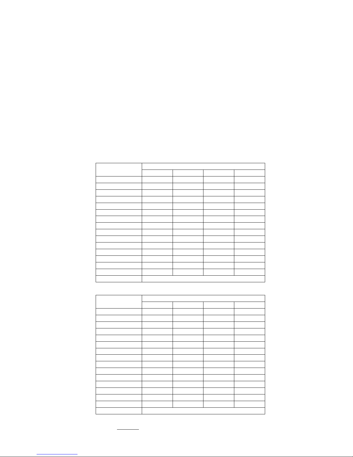
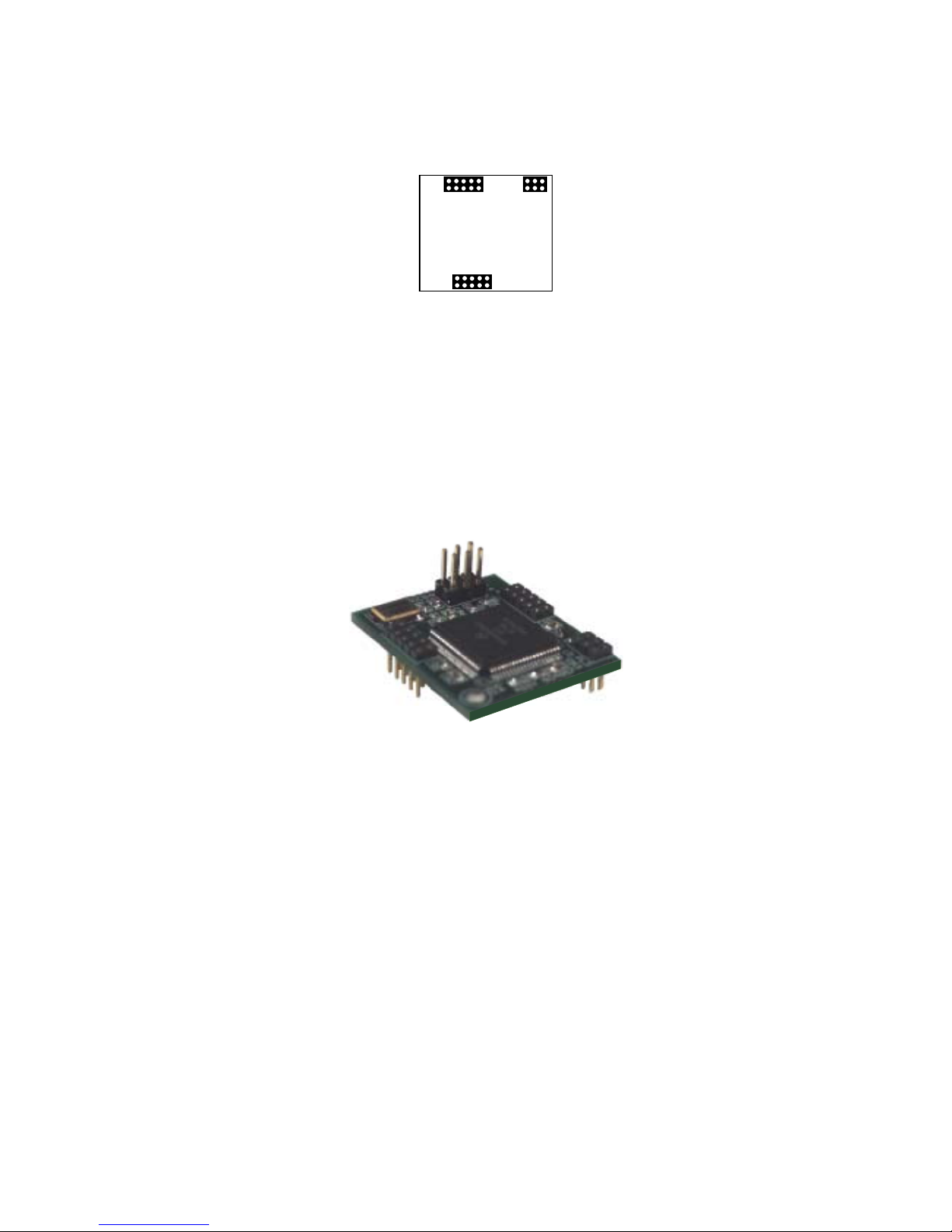
Link settings
MMM-4230 CONFIGURATION INFORMATION
Program 4230mmm.tdf LK6A Installed
LK1 IN When using Switch 1 position A ‘Variable Bandwidth’, if the frequency of an input that has an
assignment of 26.8Mb/s falls below 13.4Mb/s then the assignment will revert to 13.4Mb/s. All other
conditions mentioned in the Variable Bandwidth section still apply.
OUT The frequency resetting mentioned above does not occur.
LK2 IN Existing Reed Solomon encoding on ASI streams will pass through system.
If no RS is present on the input then RS encoding is added.
OUT Reed Solomon encoding added to input ASI steams regardless of whether existing RS encoding exists
or not.
LK3 Not used.
LK4*IN Output G.703 signal will be “framed”.
OUT Output G.703 signal will be “unframed”.
LK5*IN Output “unshaped” (recommended for output drive lengths > 68m (225ft)).
OUT Output “shaped” (recommended for output drive lengths < 68m (225ft)).
LK7 Installing this link will terminate the RS-422 data line.
Note: * Not applicable for 34 Mb/s (E3) version.
MMX-4230 CONFIGURATION INFORMATION
LK1 IN Allows instantaneous changes in channel bandwidth allocation as required by the “Variable” Data
Assignment.
OUT Error concealment is applied to the packet distribution.
LK2 IN Output packet size is always 204 byte and will contain Reed Solomon code regardless of
corresponding MMM-4230 input packet size.
OUT Output packet size matches that of corresponding MMM-4230 input packet size.
LK3 IN Outputs can be individually disabled by SNMP remote control. Note that this requires SNMP
functionality within IRT’s SNMP frame.
OUT All outputs are always enabled. SNMP functionality not required.
LK4*IN For input G.703 signal that is “framed”.
OUT For input G.703 signal that is not “framed”.
LK5 IN Input G.703 equaliser not enabled.
OUT Input G.703 equaliser enabled.
LK10 Installing this link will terminate the RS-422 data line.
Note: * Not applicable for 34 Mb/s (E3) version.