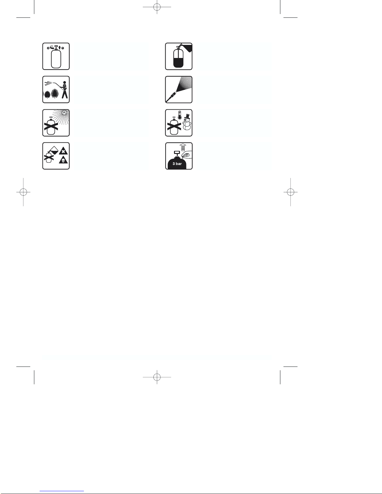
ISC GLDS 5 Gardenline User manual

GLDS 5 Gardenline , Ex, UK
Druckspritze Aldi UK Artikel-Nr.: 3425173
Ident-Nr.: 01014

Komponenten / Ersatzteile
Position Artikel-Nr. Beschreibung
7 342517201005 Filling Funnel
11 342517201063 tank
13 342517201011 pump membrane
906 342517201006 pressure relief valve
907 342517201007 manometer pos. 10a and 10b
908 342517201001 spray tube
911 342517201009 pump complete
912 342517201004 nozzle complete

Operating Instructions Pressure
Sprayer
Art.-No.: 34.251.73 I.-No.: 01014 GLDS 5
Anleitung GLDS 5 GB 16.12.2004 9:57 Uhr Seite 1

2
1 2 5
4
1
2
3
35
76
4 5
4
8
9
10
7
6A
auf
11
zu
Anleitung GLDS 5 GB 16.12.2004 9:57 Uhr Seite 2

GB
3
Safety regulations:
Please read these directions for use carefully
and observe the information provided. It is impor-
tant to consult these instructions in order to
acquaint yourself with the unit, its proper use and
safety regulations.
Suitable measures must be taken to keep the
unit out of children’s reach.
The pressure sprayer is designed for spraying
common home and garden solutions. This is pri-
marily meant to include pesticides, weed killers
and liquid fertilizers.
The pressure sprayer is not designed to spray
acidic and caustic liquids. Nor should it be used
to spray impregnating agents.
Only use a suitable nozzle wire or cleaning agent
to clean clogged nozzles.
Do not spray contents of sprayer on persons or
animals.
Always wear protective clothing when spraying
pesticides and insecticides.
Ensure that liquid sprays are not heated beyond
the permitted operating temperature of 40 °C.
When mixing and working with spray solutions,
always follow the manufacturer’s instructions.
Each time the spraying unit has not been used
for an extended period of time it should be
checked for possible damage prior to reusing it.
Immediately replace defective parts.
Use only original replacement parts.
Do not leave the unit (filled or empty) in direct
sunlight.
Before placing the unit in winter storage,
thoroughly clean and dry it out so that it is not
damaged by freezing temperatures.
We will not be liable for any damage that results
from improper repairs and/or improper handling
of the unit (e.g. using the unit in ways for which it
was not intended).
Opening the unit or performing maintenance
work on it is only permitted when the tank is
depressurized.
To relieve the pressure, pull up the funnel-sha-
ped knob connected to the safety valve.
Only use currently approved pesticides.
Please observe COSHH Material Safety Data
Sheets.
Pesticides include - but are not limited to - herbi-
cides, insecticides, fungicides and growth regula-
tors as well as materials that are intended to be
used in conjunction with these agents in order to
modify their properties or effects.
Each time after using the unit and prior to perfor-
ming any maintenance work on the unit, always
relieve the pressure via the overpressure valve
by raising the overpressure valve.
Technical data
Max. filling capacity 5 l
Total filling capacity 7 l
Volumetric flow rate, Vmax = 1.07 litres/min.
Permissible operating pressure 3 bar
Permissible operating temperature + 40°C
Safety valve / vent valve 1
Nozzle hollow cone 1 mm
Nozzle spraying angle max. 60°
Repulsion angle at the nozzle less than 5N
Assembly
Screw the spray tube (Fig. 1/Item 1) to the pistol
grip (Fig. 1/Item 2)).
Do not unscrew the overpressure valve ( Fig.
3/Item 6)!
Check to ensure that the screw connections for
the hose at the spray gun handle and on the tank
are tight!
Starting up and venting
Unscrew the feed funnel from the bottom of the
pressure sprayer (Fig. 2/Item 5).
Before you screw out the pump, raise the over-
pressure valve (Figure 3/Item 6) and let off any
overpressure that may be in the unit.
Press down the pump handle as far it will go and
slowly unscrew the pump (counter-clockwise).
Screw the feed funnel onto the tank (Fig. 3/Item
5).
Fill the container up to no further than the 5 liter
mark with the preparation you want to spray.
Follow the instructions issued by the producer of
the preparation you are using.
Remove the feed funnel from the tank.
Insert the pump, press down the pump handle as
far it will go and screw in the pump (clockwise)
until it is tight again. The pump handle latches
simultaneously into the bayonet lock.
Anleitung GLDS 5 GB 16.12.2004 9:57 Uhr Seite 3

GB
4
Important: The bayonet lock must be properly
latched whenever you transport the pressure
sprayer. Also, the spray lance should be in the
holder provided for the purpose (Fig. 4).
Screw in the pump again (clockwise) until it is
tight.
Screw the feed funnel back onto the bottom of
the pressure sprayer.
Turn the pump grip slightly counter-clockwise in
order to release it from the bayonet lock.
Pressure is built up in the tank with pumping
movements (up and down) of the pump handle.
The tank pressure at any given moment can be
read off the pressure gauge (Fig. 3/Item 7). The
maximum tank pressure (operating pressure)
must not exceed 3 bar. The overpressure valve
(Fig. 3/Item 6) triggers at a positive pressure of 3
bar and relieves any pressure exceeding this
amount.
To spray, press the trigger lever (Fig. 1/Item 3)
on the spray gun handle.
The spray jet will stop immediately you let go of
the trigger lever.
You can direct the spray precisely at even hard-
to-reach areas by bending the swan-neck (Fig.
1/Item 4) at the joints (Fig. 5).
Clean the sprayer each time after you have used
it and leave it open to dry.
You can prolong the working life of the sprayer
by occasionally applying resin- and acid-free
grease (Vaseline) to the seal rings and collars.
Please note: Severe stress during transportati-
on, use and storage, negative environmental
factors (at the point of use and storage), and
poor maintenance and care may cause the
sprayer to suffer premature wear. Each time
before you use the sprayer it is important, there-
fore, to check that it is in safe and good opera-
ting condition and that there are at least no visi-
ble signs of external damage.
We recommend that you arrange for a specialist
or Service Center to check whether the sprayer
is still safe for operation as soon as you discover
any defects with a potentially negative effect on
safety and at least every 5 years.
Maintenance
Prior to performing any maintenance work on the
unit, always relieve the pressure via the over-
pressure valve (Fig. 3/Item 6) by raising the over-
pressure valve. Be sure to observe the safety
instructions.
To change the pump membrane, pull up the
pump lever as far as it will go, turn it counter-
clockwise until you come against notable resi-
stance, and then turn it a little further counter-
clockwise until the cover plate and the bayonet
separate (Fig. 6/Item A).
Press the membrane plate (Fig. 7/Item 11) out of
its holder, insert a new membrane and lubricate
it with acid-free grease.
After using the unit and prior to performing any
maintenance work, always relieve the pressure
by simply pulling up on the funnel-shaped knob
connected to the safety/overpressure valve (Fig.
6/Item A).
Anleitung GLDS 5 GB 16.12.2004 9:57 Uhr Seite 4

5
Pull the pump lever all the way
up until it stops, then turn it
counterclockwise to unscrew it
from the tank.
Keep a firm grip on the spray
wand and do not direct the
stream toward persons!
Do not place the pressurized
tank in direct sunlight for extend-
ed periods of time!
Never fill the pressure tank with
a poisonous spray solution or
use the tank to spray it!
Always use the feed funnel when
filling the tank with a spray solu-
tion!
Flat spray pattern with angle of
60°
Do not subject the tank to nega-
tive temperatures when it is filled
with a spray solution!
Always depressurize the tank
prior to cleaning or maintaining
it!
Pull up on the relief valve to
release the pressure!
Anleitung GLDS 5 GB 16.12.2004 9:57 Uhr Seite 5

6
List of replacement parts for the GLDS 5 Art.-No.: 34.251.73 I-No.: 01014
(see Figure 1-7)
Item Descritption Replacement-No.
01 Spray tube 34.251.72.01.001
02+03 Spray gun handle complete with trigger lever 34.251.72.01.002
04 Swan-neck complete with nozzle 34.251.72.01.004
05 Funnel 34.251.72.01.005
06 Overpressure valve complete 34.251.72.01.006
07 Pressure gauge 34.251.72.01.007
08 Pressure tube with couplings 34.251.72.01.008
09 Pump complete 34.251.72.01.009
10 Carrying strap complete 34.251.72.01.010
11 Pump diaphragm 34.251.72.01.011
Anleitung GLDS 5 GB 16.12.2004 9:57 Uhr Seite 6

7
Anleitung GLDS 5 GB 16.12.2004 9:57 Uhr Seite 7

Technical changes subject to change
EH 12/2004
The reprinting or reproduction by any other means, in whole or in part,
of documentation and papers accompanying products is permitted only
with the express consent of ISC GmbH.
WARRANTY CERTIFICATE
The product described in these instructions comes with a 2 year warranty
covering defects. This 2-year warranty period begins with the passing of risk or
when the customer receives the product. Please retain receipt as proof of
purchase.
For warranty claims to be accepted, the product has to receive the correct
maintenance and be put to the proper use as described in the operating
instructions.
Your statutory rights of warranty are naturally unaffected during these 2
years.
This warranty applies in Germany, or in the respective country of the
manufacturer’s main regional sales partner, as a supplement to local
regulations. Please note the details for contacting the customer service center
responsible for your region or the service address listed below.
GARANTIEURKUNDE
Auf das in der Anleitung bezeichnete Gerät geben wir 2 Jahre
Garantie, für den Fall, dass unser Produkt mangelhaft sein sollte.
Die 2-Jahres-Frist beginnt mit dem Gefahrenübergang oder der
Übernahme des Gerätes durch den Kunden. Voraussetzung für
die Geltendmachung der Garantie ist eine ordnungsgemäße
Wartung entsprechend der Bedienungsanleitung sowie die be-
stimmungsgemäße Benutzung unseres Gerätes.
Selbstverständlich bleiben Ihnen die gesetzlichen Gewähr-
leistungsrechte innerhalb dieser 2 Jahre erhalten. Die Garan-
tie gilt für den Bereich der Bundesrepublik Deutschland oder der
jeweiligen Länder des regionalen Hauptvertriebspartners als Er-
gänzung der lokal gültigen gesetzlichen Vorschriften. Bitte be-
achten Sie Ihren Ansprechpartner des regional zuständigen Kun-
dendienstes oder die unten aufgeführte Serviceadresse.
ISC GmbH · International Service Center
Eschenstraße 6 · D-94405 Landau/Isar (Germany)
Info-Tel. 0180-5 120 509 • Telefax 0180-5 835 830
Service- und Infoserver: http://www.isc-gmbh.info
Helpline-No.:
GB 0044 (0) 151 649 1500
IRL 1890 946244
Anleitung GLDS 5 GB 16.12.2004 9:57 Uhr Seite 8
Table of contents
Popular Paint Sprayer manuals by other brands

Graco
Graco 311322L Operation, parts, service and repair

Earlex
Earlex SPRAY STATION HV 6900 Operating instructions manual

Fimco
Fimco Volt Edge 20V-20-DLX-SP owner's manual

Einhell Royal
Einhell Royal DS 5/1 operating instructions

MRC
MRC DOR-2828 Operation manual

Rongpeng
Rongpeng R450 Operating Instruction and Safety Manual