ISHIDA WPL-3000 User manual

Manual No. 0077B 48725
IMPORTANT
•Do not carry out installation,operation,service,or
maintenance until thoroughly understanding the
contents of this manual.
•Keep this manual available at all times for instal-
lation, operation, service, and maintenance.
SERVICE MANUAL
WPL-3000

You can help improve this manual by calling
attention to errors and recommending
improvements. Please express your
comments to the nearest Ishida Company
representative. Thank you!
Copyright 2001 by Ishida Co., Ltd. All Rights Reserved.
No part of this manual may be reproduced in any form, by photocopy or any
other means, without written permission from the publisher.
SAFETY CONSIDERATIONS
These safety measures must be followed to ensure the safe servicing of this machine:
Servicing is to be done by qualified service personnel only
These service instructions are for use by qualified service personnel who fully
understand the potential hazards involved. To avoid any possible danger, do not
perform any service procedures unless qualified to do so.
Perform only the specified service procedures
To ensure personal safety, do not perform any service procedures which are not
specifically mentioned in this service manual.
Properly ground machinery
As a Class 1 electrical device, this machine requires protective grounding for safe
operation.
Avoid servicing while power is being supplied
Machine servicing while power is being supplied and covers or enclosures are
opened or removed should be avoided as much as possible. When servicing cannot
be performed by any other means, service personnel should take precautions against
the danger of electrical shock or other potential hazard involved.
Take precaution against residual electrical charge hazard
Capacitors inside the machine may still hold an electrical charge even after power is
disconnected.
Use same type fuses and components for replacement parts
To avoid the potential hazards involved, do not replace fuses or components with
types other than those specified in the parts list for this machine.
Power supply to the machine is disconnected only when the electrical plug
is removed from the electrical outlet. For protection against electrical shock,
remove plug before performing any servicing to the machine.
WARNING
The following symbols are used to alert service personnel of potential danger or
special circumstances related to the safe and proper servicing of this machine:
WARNING
WARNING
Precautions which must be followed to prevent the possibility
of death or serious injury.
Precautions which must be followed to prevent the possibility
of light or moderately severe injury to personnel or damage to
the equipment.
Important information for the operation of the machine.
NOTE:

GETTING STARTED
This service manual contains the procedures for servicing the WPL-3000 Index
Conveyor. It is strongly advised that you read and clearly understand the
contents of this manual before beginning any maintenance to this machine.
To insure the safety and long operating life of this machine, it is important to
observe the following precautions:
Keep the area around the machine clear of any dust and debris.
Do not leave screws or other foreign objects in the machine after
performing routine maintenance since this can cause major damage to the
machine when the electrical switch is turned on.
Always remove wires by holding the connector and pulling to disconnect.
Do not disconnect by pulling on the wires themselves since this may cause a
wire to snap or damage the connection.
Before assembling or adjusting this machine, make sure you thoroughly
understand and follow each step in the order indicated in this manual.
MAINTENANCE PRECAUTIONS

Contents
Table of Contents
1. Overview 1.1 External Parts and Names (I Line Type) .........
1.2 External Parts and Names (L Line Type) ........
1.3 Location of Safety Stickers .............................
1-2
1-3
1-4
2. Setup 2.1 Confirm Before Delivery
2.1.1 Location..................................................
2.1.2 Installation Route ...................................
2.1.3 Electrical Power .....................................
2.1.4 Setup Environment.................................
2.1.5 Work Clothes ..........................................
2.2 Necessary Items for Installation
2.2.1 Tools .......................................................
2.2.2 Manuals..................................................
2.3 Package Confirmation ....................................
2.4 Positioning and Adjusting
Conveyor Stands
2.4.1 Fastening to Stand .................................
2.4.2 Fastening Stands ...................................
2.4.3 Stand Fastening Method 1 .....................
2.4.4 Stand Fastening Method 2 .....................
2.5 Connecting Cable ...........................................
2.6 Setup Procedures ...........................................
2.7 Method for Threading Labels ..........................
2.8 WPL-3000 USA Rescue Mode .......................
2-2
2-2
2-2
2-2
2-3
2-3
2-3
2-4
2-5
2-6
2-7
2-7
2-8
2-9
2-10
2-11
3. Test Mode 3.1 Menu Directory Diagram .................................
3.2 Test Mode
3.2.1 Starting Test mode .................................
3.2.2 Hardware Test (C01) ..............................
3.2.3 RAM Clear (C02)....................................
3.2.4 Thermal Head Setting (C03) ..................
3.2.5 Sensor Check (C04)...............................
3.2.6 Extra Memory (C05) ...............................
3.2.7 Setting ROM Switch (C06) .....................
3.2.8 Label Format Editing (C07) ....................
3.2.9 Sales Mode Setting (C08) ......................
3-2
3-3
3-3
3-6
3-7
3-9
3-9
3-9
3-12
3-12

Contents
3.2.10 Machine ID No. Setting (C09) ................
3.2.11 Preset Function Setting (C10) ................
3.2.12 Password (C11) .....................................
3.2.13 Data Transmission (C99) .......................
3-13
3-14
3-14
3-15
4. Setting Mode 4.1 Menu Directory Diagram..................................
4.2 Setup Mode
4.2.1 Label Format (b01).................................
4.2.2 Bar Code Setting (b02) ..........................
4.2.3 Code Settings (b03) ...............................
4.2.4 Setting Initial Data (b04).........................
4.2.5 PLU File (b08) ........................................
4.2.6 Preset Report (b10)................................
4.2.7 Registration Select (b11) ........................
4.2.8 Total Mode Select (b12) .........................
4.2.9 Password (b13) ......................................
4.2.10 Tray Master Registration (b15)...............
4.2.11 Conveyor Setup (b16) ............................
4-2
4-5
4-7
4-8
4-9
4-11
4-12
4-14
4-15
4-15
4-16
4-16
5. Controller Unit 5.1 Overview .........................................................
5.2 Block Diagram.................................................
5.3 Electronic Parts
5.3.1 Display Board .........................................
5.3.2 Junction/Buzzer Board............................
5.4 Display and Key Check ..................................
5.5 Disassembly Diagram .....................................
5-2
5-3
5-3
5-4
5-6
5-7
6. Weigh Conveyor 6.1 Overview .........................................................
6.2 Block Diagram ................................................
6.3 Electronic Parts
6.3.1 Load Cell Unit.........................................
6.3.2 A/D Converter Board ..............................
6.4 Scale Check ...................................................
6.5 Disassembly Diagram .....................................
6-2
6-3
6-4
6-5
6-6
6-7

Contents
7. Printer / Label
Applicator Unit
7.1 Overview .........................................................
7.2 Block Diagram ................................................
7.3 Electronic Components ..................................
7.3.1 Printer Unit
(Thermal head, label sensor adjustment) ...
7.3.2 Label Applicator Unit ..............................
7.4 Adjustment Position of
the Label Applicator Unit .................................
7.5 Movement Test ...............................................
7.6 Disassembly Diagram (Stand Unit) ................
7.7 Disassembly Diagram (Printer Unit). ..............
7.8 Disassembly Diagram (Label Applicator Unit) ..
7-2
7-3
7-4
7-4
7-10
7-14
7-15
7-16
7-16
7-17
8. Weigh Conveyor
Unit
8.1 Weigh Conveyor Unit ......................................
8.2 Block Diagram ................................................
8.3 Electronic Components ..................................
8.3.1 Power Supply Unit..................................
8.3.2 Drive Board (P-854) ...............................
8.3.3 Electromagnetic Valve ............................
8.3.4 Air Cylinder.............................................
8.3.5 Application Timing Sensor......................
8.4 Elevator Check and Parts Adjustment ............
8.4.1 Weigh Conveyor .....................................
8.4.2 Conveyor Fall Prevention Screw
Adjustment .............................................
8.5 Disassembly Diagram......................................
8-2
8-3
8-4
8-4
8-5
8-5
8-6
8-7
8-8
8-8
8-9
8-10
9. Troubleshooting 9.1 Periodic Parts Replacement ...........................
9.2 Breakdown and Countermeasure ...................
9.3 Error Messages ..............................................
9-2
9-3
9-4
10. Load Cell Unit
Appendix
10.1 Location of Main Parts ....................................
10.2 Replacing the Load Cell Unit ..........................
10.3 Span Calibration Adjustment ..........................
A.1 Installation Notes ............................................
A.2 Label Format Worksheets...............................
10-2
10-3
10-6
A-2
A-9

Contents

Chapter 1
Overview
1.1 External Parts and Names (I Line Type) .........
1.2 External Parts and Names (L Line Type) ........
1.3 Location of Safety Stickers .............................
1-2
1-3
1-4
WPL-3000 SERVICE MANUAL 0077B
1-2
Overview 1
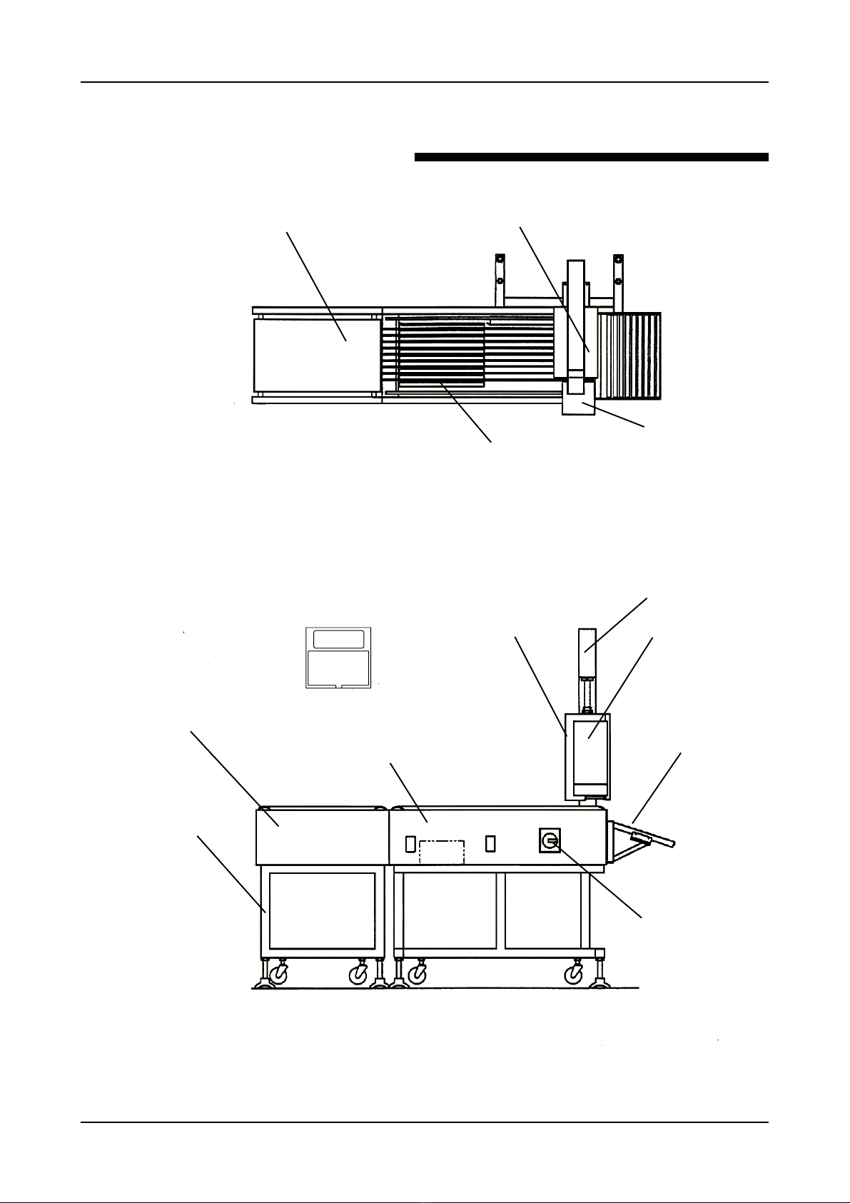
Fig. 1. 2 WPL- 3000 ( I Line Type) front view.*
CONTROLLER UNIT
INFEED CONVEYOR UNIT (OPTION)
PRINTER STAND
PRINTER UNIT
CONVEYOR WEIGH UNIT
LABEL APPLICATOR
DISCHARGE ROLLER UNIT
(OPTION)
POWER SWITCH
1.1 EXTERNAL PARTS AND NAMES
CONVEYOR STAND
(OPTION)
Fig. 1.1 WPL- 3000 ( I Line Type) top view.*
INFEED CONVEYOR UNIT (OPTION) PRINTER UNIT
SCALE
LABEL APPLICATOR
( I LINE TYPE )
* IMPORTANT NOTE – later versions of the WPL-3000 use a front mounted printer arm.
Table of contents


