ISIC PCM4-Q87 User manual

User Manual
PCM4
Q87 version

User Manual PCM4-Q87 version
P/N: 07355-000 Rev B
Page 2/16
Disclaimer
ISIC A/S makes no representation or warranties with respect to the contents or use of this
manual, and specifically disclaims any express or implied warranties of merchantability or
fitness for any particular purpose. Further, ISIC A/S reserves the right to revise this
publication and to make changes to its content at any time, without obligation to notify any
person or entity of such revisions or changes.
FCC Warning
Computing devices and peripherals generate, use, and can radiate radio frequency energy, and
if not installed and used in accordance with the instructions advised by ISIC A/S, may cause
interference to radio communication.
The PCM4 series of PC’s, manufactured by ISIC A/S, is designed to comply with the emerging
generic EEC standards, that cover applications in maritime environment.
Classification
The PC is classified as Environmental condition “protected” acc. to EN60945 ed. 4.
Approvals
Approval according to EN60945 ed. 4; Maritime navigation and radio communication
equipment and systems –General requirements.
ISIC A/S is complying with the WEEE directive within the European Union, stating that
electronic and electric products must be collected separately. Products are marked according
to the directive.
Copyright 2013 ISIC A/S
ISIC P/N: 07355-000 Rev B
ISIC A/S
Edwin Rahrs Vej 54
DK-8220 Brabrand
Denmark
Phone: +45 70 20 70 77
Fax: +45 70 20 79 76
Web: http://www.isic-systems.com

User Manual PCM4-Q87 version
P/N: 07355-000 Rev B
Page 3/16
ISIC PCM4 User Manual
Congratulations on your purchase of ISIC PCM4. This short form manual is designed to get you
started working with your new PCM4. It is not meant to cover all possible options or situations.
For a more detailed description of the PCM4 motherboard, please read the fully comprehensive
Main Board Manual obtainable on the CDROM.
Package contents:
1 PCM4
1 CDROM containing PCM4 Manual and Main Board Manual (optional)
1 Power cable (optional)
If any of these items are not present, please contact ISIC.

User Manual PCM4-Q87 version
P/N: 07355-000 Rev B
Page 4/16
Table of Contents
1GENERAL CONSIDERATIONS ON INSTALLATION AND OPERATION ....................... 5
2GETTING STARTED ................................................................................................ 5
3PCM4 Q87 OVERVIEW ........................................................................................... 6
4MOTHERBOARD CONNECTION OVERVIEW............................................................. 7
5INSTALLING ADDITIONAL EXPANSION CARDS ................................................... 11
6TECHNICAL SPECIFICATIONS (29/10-2015) ...................................................... 12
7MECHANICAL DIMENSIONS................................................................................. 14
8MOUNTING POSITIONS....................................................................................... 15
9PCM4 SYSTEM INDICATORS ................................................................................ 15
10 TROUBLESHOOTING ......................................................................................... 15
11 SERVICING THE UNIT....................................................................................... 15
12 GENERAL NOTES ON USB.................................................................................. 15
13 ISIC INFO / SUPPORT ...................................................................................... 16
14 REVISION HISTORY ......................................................................................... 17

User Manual PCM4-Q87 version
P/N: 07355-000 Rev B
Page 5/16
1General considerations on Installation and
Operation
The PCM4-Q87 is designed to work at conditions according to IEC 60945. However, keeping
the temperature and vibration level at a minimum will extend the life time of the product. ISIC
recommend operating this product at normal room temperature (20-25 °C), with the lowest
level of vibration and humidity.
Installation of the PCM4-Q87
When designing the cabinet/console for the PCM4-Q87, please ensure that air can flow freely
around the cabinet, in order to avoid any unnecessary rise in temperature. If it is not possible
to have an adequate natural airflow, use a fan to force the airflow to be higher.
2Getting started
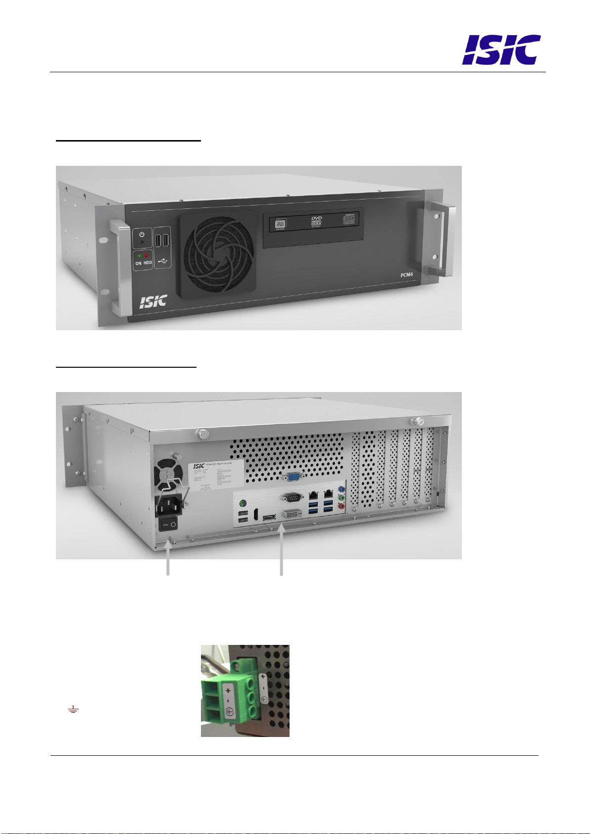
Please refer to the PCM4 overview for location of connectors specified in this section.
Connect Keyboard/Mouse to the connector specified in PCM4 overview or connect to the USB
connectors.
Connect the monitor to the VGA, DVI, HDMI or DisplayPort connector.
Connect all other needed connectors ending with the Power outlet.
Press the ON/OFF button to “I” position.
To power up the PCM4, you need to press the power button on the front (dependant on BIOS
setting). Use a pencil or similar for that purpose.
The PCM4 will be in standby mode when you power down. To restart the PCM4 again, use a
pencil on the power button.

User Manual PCM4-Q87 version
P/N: 07355-000 Rev B
Page 6/16
3PCM4 Q87 overview
Front view PCM4-Q87
Rear view PCM4-Q87
Power DC:
+ : 24V DC
- : 0V
: Chassis
Power ac
See Motherboard Connection Overview
(next page)

User Manual PCM4-Q87 version
P/N: 07355-000 Rev B
Page 7/16
4Motherboard connection overview
Below is an overview of motherboard connections and pin-out of the same.
(1)

User Manual PCM4-Q87 version
P/N: 07355-000 Rev B
Page 8/16
(2)
(3)
(4)
(5)
(6)

User Manual PCM4-Q87 version
P/N: 07355-000 Rev B
Page 9/16
(7)
(8)
(9)
(10)
(11)

User Manual PCM4-Q87 version
P/N: 07355-000 Rev B
Page 10/16
(12)
(13)
(14)
(15)
(16)

User Manual PCM4-Q87 version
P/N: 07355-000 Rev B
Page 11/16
5Installing additional expansion cards
Always disconnect the Power outlet before removing the top cover.
Remove the 2 thumb screws and top cover.
Remove the slot screw and remove the blind bracket. Install the add-on card in the slot and
then replace the slot screw. Replace the top cover and fasten the 2 screws at the rear.
PCM4-Q87 motherboard
ATTENTION - This marine computer is covered by ISIC warranty, and any alterations
may render marine certificate and warranty invalid
PCIe x 16
PCIe x 4
PCIe x 1
3 times PCI

User Manual PCM4-Q87 version
P/N: 07355-000 Rev B
Page 12/16
6Technical specifications (29/10-2015)
PCM4-Q87 –General
CPU:
Core™ i3-4360 (2 Cores, 4 Threads)
Optional Core™ i5-4590S (4C/4T)
Optional Core™ i7-4790S (4C/8T)
Optional Pentium G3420 Dual Core
Chipset:
Intel® Q87
64Bits, Intel® Virtualization Technology, Intel® vPro Technology, Intel® ME v9.0,
Intel® Rapid Storage Technology, Intel® Smart Connect Technology, Intel® Smart
Response Technology, Intel® Stable Image Platform Program (SIPP), Supports
Hyper-Threading, Enhanced SpeedStep® and Turbo Boost Technology
Memory:
4 GB DDR3 RAM 1600 MHz (Standard)
Optional Upgrades
4 DIMM sockets supporting up to a total of 32GB DDR3 1333/1600 RAM
Video:
On-CPU Intel HD Graphics 4600
The maximum supported resolution is 4096x2160 (HDMI)
OpenGL 4.0, OpenCL 1.2 compliant
DirectX 11.1 / Shader model 5
Tripple independent display support
Optional PCIe x16 graphics card
Audio:
6-channel Audio (Realtek ALC887)
Ethernet:
1x 10/100/1000 Mbit/sec Ethernet Intel® PHY I217LM (support AMT 9.0)
1x 10/100/1000 Mbit/sec Ethernet Intel® I210AT
Optional 1,2 or 4x RJ45 on add-on card
Hard Disk Drive:
80+GB 2.5”, SATA (Standard)
Optional Upgrades
500GB and 1TB, disk, 2.5” SATA
Solid State Disc 80GB, 100GB... up to 1600GB
5¼” drive bay:
DVD-R/W Drive (SATA interface)
Optional Combined Removable Solid State disk drive and Slide-in DVD drive
PCM4-Q87 - Ports
Video:
HDMI + DP + DVI-D + VGA video out
Audio:
3x 3.5mm jack socket (Line in, Line out, Mic in)
Ethernet:
2x RJ45
Serial:
1x RS232/422/485 un-isolated
Optional 2 x RS232 un-isolated..
USB:
4x USB 3.0 ports on back
10x USB 2.0 ports (2 on back, 6 on internal headers and 2 on front)
SATA:
6x 6.0Gb/s SATA
RAID 0,1,5,10 supported by onboard Intel Rapid Storage Technology
Expansion Slots:
1x PCI Express x16, 1x PCI Express x4, 1x PCI Express x1, 3x PCI
PCM4-Q87 –Power
Standard:
90-264 VAC, 50-60 Hz, max 300 Watt Typ 35-130Watts
Automotive:
18-36 VDC max 300 Watt Typ 35-130Watts
PCM4-Q87 –Environmental
Operating
Temperature:
-15 to 55 °C
Storage Temperature:
-25 to 70 °C
Relative Humidity:
8 to 90 %
2 page flyer rev. 29.10.2015. Technical specifications are subject to change without prior
notice. For drawings and full technical specifications please consult the
users manual.

User Manual PCM4-Q87 version
P/N: 07355-000 Rev B
Page 13/16
PCM4-Q87 - Approvals
CE Mark:
EN61000-6-2, EN61000-6-4, EN61000-6-1 & EN61000-6-3
Marine:
Type Approvals:
IACS E10 rev. 6 & IEC 60945 Ed. 4
For latest marine class approvals –see www.isic-systems.com
PCM4-Q87 - Dimensions
Basic Version:
420 x 132 (3U) x 380 mm
Brackets:
Mounting-angles - Optional 19” brackets for 19” rack-mount (on shelf)
Weight:
11 Kg

User Manual PCM4-Q87 version
P/N: 07355-000 Rev B
Page 14/16
7Mechanical dimensions
1
1
2
2
3
3
4
4
5
5
6
6
A A
B B
C C
D D
Approved by
Projection method: Drawing size:
Units: mm
Designed by
General tolerances: 0,2
Hole position: 0,1
Angle, straightness and flatness: DS/ISO 2768-H
Scale: Drawing no.
Replaces:
Rev.
Subject:
ISIC A/S, Edwin Rahrs Vej 54, DK-8220 Brabrand. Tlf.: +45 70207077. Web: www.isic.dk
This docoment contains proprietary information and is not to be
used or reproduced without the written permission of ISIC A/S
Material: Surface:
Sheet: 1 of 1
ksc 29-09-2015
A3
PCM4 IMBA-Q87 AC ISIC
NJS 29-09-2015
1:4 06800-001 A
Cabinet 420,5
Whit horizontal Bracket 478
Cabinet 391,5
Whit front handle 419,3
Mounting holes Horiz. 250
Mounting holes Horiz. 458
4x Ø8
95,5 x 95,5 148,3 42,6
47,4
44,6
0
82
70
92,2
0
30
108
243,5
Cabinet 132,9
Mounting holes vertical. 466
57,15
Mounting holes vertical.
37,7
Air inlet
A
A
A ( 1 : 4 )
23
80
Ø38
PSU air outlet
4x 6,8
Air outlet
4x USB 3
2x LAN
RS 232/422/485
DVI-D
Display port
2x RS 232
2x USB 2
HDMI VGA
Ground M6
Mic - Audio in/out
Power on/off
Power led
HD led
2x USB 2
DVD
AC power
PS2

8Mounting positions
The PCM4 can be mounted in horizontal and vertical positions, but NOT upside down.
If needed, it is also possible to mount the PCM4 with the DVD drive facing downwards.
9PCM4 System Indicators
The PCM4 is equipped with two LED’s, located on the case front.
LED Indication
Description
Green
System is on.
Red
Indicate activity of SSD.
10 Troubleshooting
Problem
Cause
Solutions
The PCM4 won’t start
- There is no power
connected
- Connect the power cord
- The ON/OFF button at the
rear side is in the ‘O’ position
(ac version only)
- Push the ON/OFF button to
the ‘I’ position
- The power button on the
front has not been pressed
- Use a pencil on the power
button
- USB power overload
- Read paragraph “General
notes on USB”
The PCM4 starts, but there is
no picture on the screen
- The display cable is not
connected, or have fallen out
- Connect the display cable
- Your brightness/contrast on
the monitor is either at max
or min level.
- Turn the brightness/contrast
to the correct levels.
11 Servicing the unit
In case that the unit still fails after following the troubleshooting send the unit to ISIC for
repair. There are no user serviceable parts inside.
12 General notes on USB
In the USB specification a max power consumption of 500mA on each USB port is specified.
If you experience start- up problems, start by removing all USB devices, and then try to
restart the PCM4 again.
Faulty USB devices can also cause malfunction of your PCM4.

User Manual
P/N: 07355-000 Rev B
Date: 19/08/2016
PCM4-Q87 version
Page 16/16
13 ISIC info / Support
In case you have inquiries or problems with your PCM4, you have a number of possibilities to
get support.
Company name: ISIC A/S
Head office: Edwin Rahrs Vej 54
DK –8220 Brabrand
Denmark
Shipping address: Holmstrupgaardvej 5
DK-8220 Brabrand
Denmark
Telephone: +45 70 20 70 77
Fax: +45 70 20 79 76
Mail: mail@isic-systems.com
www: www.isic-systems.com
VAT number: DK 16 70 45 39
Bank Name/Address: Handelsbanken A/S
Havneholmen 29
DK –1561 København V
Denmark
Bank Code: 0892
SWIFT: HANDDKKK
IBAN for DKK: DK53 0892 0001 0159 69
IBAN for EUR: DK48 0892 0003 0026 19
IBAN for USD: DK26 0892 0003 0026 27
Contacts:
RFQ’s: By fax to +45 70 20 79 76
By mail to sales@isic-systems.com
Orders: By fax to +45 70 20 79 76
By mail to orders@isic-systems.com
Support: Via homepage www.isic-systems.com under aftersales
By mail to service@isic-systems.com
During office-hours (Mo-Fr: CET 0800 - 1600) at +45 70 20 70 77
Service: Before shipment for service Request Return Material Authorisation
number at homepage www.isic-systems.com under RMA
By mail to service@isic-systems.com

User Manual
P/N: 07355-000 Rev B
Date: 19/08/2016
PCM4-Q87 version
Page 17/16
14 Revision history
Rev A
Oct 2015
Release
Rev B
Jan 2016
Pictures updated
Table of contents
Other ISIC Desktop manuals