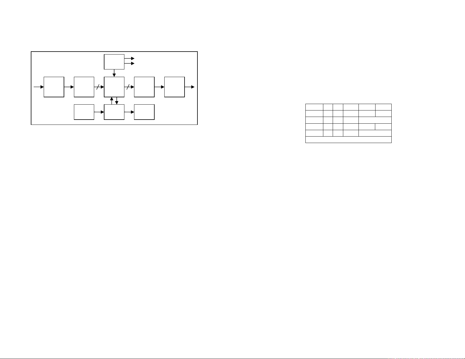
Functional block diagram
Installation and operation
The 4462A is simple to use and install.
•Set the dipswitches by referring to the table and description below
or the table on the rear of the unit.
•Connect a valid 270Mb/s SDI input.
•Connect SDI and analog outputs.
•Apply power to the 4462A unit either via the locking power
connector from the 4000 external power supply or by sliding into
the 1 RU or 2RU rack mounting frame with central power supplies.
An alternative power source can used to power the unit as long as
the input power is within the range stated in the specifications.
•On power-up the 4462A will perform a short (3 second) self-test.
The group LEDs will flash while this is in progress.
•The signal LED will be green when there is power and a valid
270Mb/s SDI signal present or red when there is power but no SDI
signal.
•One of the group LEDs will light corresponding to the group
selected by the switches. This LED will be green if the unit is
receiving a valid video signal and successfully de-embedding audio
from the selected group. The LED will otherwise be red.
•The switch settings can be altered while the unit is powered and the
changes are implemented immediately.
•The 4-800MB mounting bracket can be used to install a MiniBlox
unit. The bracket should first be fixed vertically to any surface. The
MiniBlox can then be lowered onto the dovetail part of the bracket
with the front endplate uppermost to retain it.
Switch settings
Switch 1 2 Switch OFF ON
Group 1 OFF OFF 3 18DBu 24DBu
Group 2 OFF ON 4* Custom level
Group 3 ON OFF 5 625 lines 525 lines
Group 4 ON ON 6 Set custom level
*Disables switch 3 and allows custom levels to be set
•Switches 1 & 2 set the group from which audio packets are to be
extracted.
•Switch 3 selects between analog output levels of 18DBu and
24DBu (when switch 4 is in the OFF position)
•Switch 4 over-rides the switch 3 setting and selects the custom
level. This is 20DBu on delivery but can be altered (see below).
•Switch 5 sets the video standard. For correct operation of the unit
this must match the format of the SDI signal.
•Switch 6 is used to set custom analog output levels. If switch 6 is
left on for more than six seconds the unit will enter custom level
select mode – all group LEDs will flash red while the unit is in this
mode. Refer to the next section for selecting custom levels.
Custom level select mode
To meet all international analog audio full scale output levels the 4462A has
a custom analog output level select mode. In this mode it is possible to
select any output level between 12DBu and 26DBu in 0.5DBu increments.
The default value of the custom level on delivery is 20DBu. Once the value
of the custom level is altered it will remain stored in memory until changed
again.
Serializer
10
Input
equalization
and re-
clocking
Deserializer Output
Drivers
10
Embedded
Audio
DEMUX
LEDs
Control
Switches
Micro-
controller
24 bit DAC Analog
Outputs
SDI
Input
SDI
Output