Iskra MI485 User manual

Instructions Manual
Communication Interfaces MI485 / MI486 / MI488

2 Instructions Manual of Communication Interfaces MI485 / MI486 / MI488
Table of Contents
1DESCRIPTION ...........................................................................................................................................................................3
1.1 MI485 ..................................................................................................................................................................................3
1.2 MI486 AND MI488............................................................................................................................................................. 3
2CONNECTION ...........................................................................................................................................................................3
2.1 MI485 ..................................................................................................................................................................................3
2.2 MI486 AND MI488............................................................................................................................................................. 3
3SETTING..................................................................................................................................................................................... 4
3.1 MI485 ..................................................................................................................................................................................4
3.2 MI486 AND MI488............................................................................................................................................................. 4
3.2.1 SETTING ethernet CONNECTION ............................................................................................................................ 4
3.2.2 »DeviceInstaller« PROGRAM INSTALLATION AND INTERFACE SETTING..................................................... 5
3.2.2.1 Setting fixed IP address ...........................................................................................................................................5
3.2.2.2 Communication interface configuration ..................................................................................................................6
3.2.3 INSTALLATION OF COM PORT REDIRECTOR« PROGRAM AND SETTINGS ...............................................9
3.2.3.1 Setting of virtual com port .......................................................................................................................................9
4TROUBLE SHOOTING............................................................................................................................................................11
4.1 MI485 ................................................................................................................................................................................11
4.2 MI486 AND MI488........................................................................................................................................................... 11

Instructions Manual of Communication Interfaces MI485 / MI486 / MI488 3
1DESCRIPTION
1.1 MI485
The MI485 communication interface converts an RS485 signal to an RS232 signal and viceversa. The signals are electrically
isolated. The communication interface is designed for connecting instruments with RS485 communication to RS232
communication (a PC, PLC, etc.). The MI485 interface with corresponding equipment enables setting and reading the instruments
with communication rate up to 115.2 kbps.
1.2 MI486 AND MI488
MI486 and MI488 communication interfaces are designed for connecting the instruments with RS232 or RS485 communication to
ethernet network. They enable connection of the instruments with a PC via ethernet network. The signals are electrically isolated.
The interfaces are designed only for reading data from intruments (with corresponding software). They enable communication rate
up to 115.2 kbps.
2CONNECTION
2.1 MI485
Three groups of terminals should be connected to the MI485 communication interface:
•Auxiliary power supply: It is connected to terminals 13 and 14. Auxiliary voltage value is written on the interface front
label.
•RS232 communication: Connect it according to the table below. Maximal length is 3 meters.
MI485 Computer – DB9
Tx (26) Rx (2)
Rx (24) Tx (3)
GND (25) GND (5)
•RS485 communication: It enables connection of up to 32 devices. The line should be terminated with a 120 Ωresistor.
Connection is made according to the table below.
MI485 RS485 instruments
A (21) DATA +
B (23) DATA -
After connection to power supply voltage, the Power LED indicates the presence of supply, while diodes Rx and Tx indicate data
transfer.
2.2 MI486 AND MI488
Three groups of terminals should be connected to the communication interface MI486 or MI488:
•Auxiliary power suppy: It is connected to terminals 13 and 14. Auxiliary voltage value is written on the interface front
label.
•Ethernet connection: Connect the ethernet cable to 10/100 RJ45 terminal on the communication interface and connect it
with ethernet network.
•RS232 communication (for MI486): Connect it according to the table below. Maximal length is 3 meters (CROSS-
OVER cable).
MI486 RS232 instruments
Tx (23) Rx
Rx (21) Tx
GND (22) GND
•RS485 communication (for MI488): It enables connection of up to 32 devices. The line should be terminated with 120 Ω
resistor. Connection is made according to the table below.
MI488 RS485 instruments
A (21) DATA + (A)
B (23) DATA – (B)

4 Instructions Manual of Communication Interfaces MI485 / MI486 / MI488
After connection to power supply voltage, the Power LED indicates the presence of power supply, while the diodes on the ethernet
terminal indicate the presence of the ethernet network. If network is active, one LED is lit or is blinking (the left LED indicates 10
Mb/connection /activity, and the right LED indicates 100 Mb/s connection/activity).
LEFT LED RIGHT LED
3SETTING
3.1 MI485
The MI485 communication interface does not need any setting for its operation; however, measuring instruments connected to
RS485 communication should be set. Measuring instruments connected to RS485 net should have different addresses set (when
purchased their address is 33). They should also have the same communication rate (at purcase it is 9600 bits/s). The MiNet
program is recommended for parameter setting..
3.2 MI486 AND MI488
Parameters for ethernet connection should be set for the MI486 and MI488 communication interfaces before the first application.
Parameters are set by means of the Deviceinstaller program. Its installation and description of settings are described in item 3.2.2.
The RS485 net connected to the MI488 interface should also be set. We recommend to set the net by means of the MI485 interface
and the MiNet program (see item 3.1). The programs for setting the interfaces are avaliable on the CD marked MI48x.
3.2.1 SETTING ETHERNET CONNECTION
The communication interface should have a unique IP address in the ethernet net. Two ways of assigning the IP are described
below.

Instructions Manual of Communication Interfaces MI485 / MI486 / MI488 5
oFixed IP address: In most installations the fixed IP address is required. The IP addresses are usually defined by the
system administrator. The IP address should be within a valid access, it should be unique for your net and in the same
subnet as your PC. Before setting the interface the following data are required:
IP address: ___.___.___.___
Subnet mask: ___.___.___.___
Gateway: ___.___.___.___
oDHCP: Automatic method of assigning IP addresses, i.e. DHCP, is used by many nets. If you are not sure whether
DHPC is used by your net, check it at your system administrator. At the first connection, the interface searches for a
DHPC server. The net can be checked for your device IP address, assigned by the DHCP server, with the DeviceInstaller
program. It can then be added to the list of devices on the net.
3.2.2 »DEVICEINSTALLER« PROGRAM INSTALLATION AND INTERFACE SETTING
Insert CD MI48x into your CD–ROM device.
Click a Start button and select Start in a toolbar.
Find a CD and choose Setup.exe in the Device_Installer directory (e.g.. E:\Device_Installer\Setup.exe).
Follow recommended settings by the installation wizard.
After program installation, restart the PC.
3.2.2.1 Setting fixed IP address
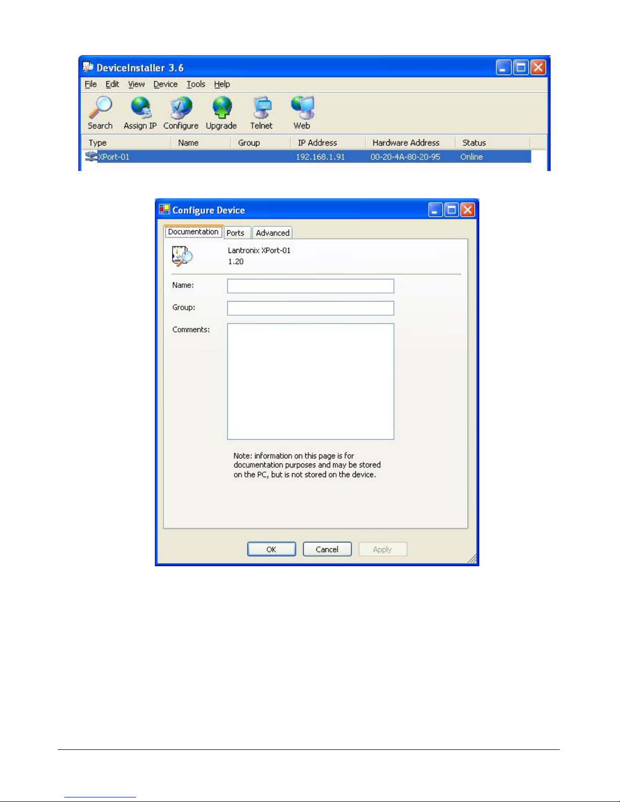
1. Click the Start button and choose Programs ÎLantronix ÎDeviceInstaller ÎDeviceInstaller in order to start
the application.
2. Click the Assign IP icon for a display of the next dialogue window displayed below.
3. Write the Ethernet address or a MAC number (see a label), and click the Next button.
4. When assigning the IP address, choose the option below – Assign a specific IP address and click the Next button.
5. Write the IP Address, Subnet Mask and Default gateway and click the Next button.
6. Click the Assign button; if the IP address has been successfully set, Completed successfully is displayed.
7. Click the Finish button to restore the Deviceinstaller window.
8. Click the Search icon; if the IP address has been successfully assigned, the Type and the IP address are displayed.
NOTE: Microsoft NET program should be installed before the DeviceInstaller program installation. The program
can be found on the enclosed CD in the Microsoft_NET directory. At startup, follow recommended settings by the
installed wizard.

6 Instructions Manual of Communication Interfaces MI485 / MI486 / MI488
3.2.2.2 Communication interface configuration
1. Click the selected interface type. A window below is displayed.
2. Click the Configure icon.
3. Your own remarks regarding the interface can be written on the Documentation tab (e.g. location, a type, etc.)

Instructions Manual of Communication Interfaces MI485 / MI486 / MI488 7
4. Set communication parameters on the Ports tab.
5. Click the Edit Settings key and write required communication parameters.. WARNING! The rate that is set in a
window below is a maximal rate for communication of the program and the measuring instrument.

8 Instructions Manual of Communication Interfaces MI485 / MI486 / MI488
6. Set a corresponding local port on the Advanced tab. If the communication interface is used together with the Com
Port redirector program (setting are described in continuation), the local port should be selected within the range from
14000 to 14010.

Instructions Manual of Communication Interfaces MI485 / MI486 / MI488 9
3.2.3 INSTALLATION OF COM PORT REDIRECTOR« PROGRAM AND SETTINGS
Insert an MI48x CD in your CD–ROM device.
Click the Start buttom and choose Start in a toolbar.
Find a CD and choose red32bit.exe in the Redirector directory (e.g.. E:\ Redirector\red32bit.exe).
Follow recommended settings by the installation wizard..
After the program installation, restart the PC.
The Com Port Redirector program redirects data from the ethernet network to the virtual serial or COM port. In this way the
access to the measuring instruments connected to the MI486 and in MI488 communication interfaces via ethernet networks is also
enabled with the programs designed only for communication via serial connection (COM).
3.2.3.1 Setting of virtual com port
1. Click the Start button and choose Programs ÎLantronix Redirector ÎConfiguration in order to start the application.
2. Click the Com Setup key for a display of a dialogue window displayed below. Choose a free COM port – marked
black (COM4 in the below example) and press the OK key.
3. Click the Add IP key for a display of the dialogue window displayed below. Write the IP address of the
communication interface (it has been set in chapter 3.2.2.1) in the Host window, nad write for 11000 smaller digit in
the TCPPort window as in case of local port setting in DeviceInstaller (chapter 3.2.2.2), e.g. 14003 / 3003. Then
presss the OK button.

10 Instructions Manual of Communication Interfaces MI485 / MI486 / MI488
4. Click the Save key in the main dialogue window and confirm the data on the screen. In this way the virtual COM port
has been successfully set..
After setting the virtual COM port restart the PC.

Printed in Slovenia •Subject to change without notice •Version 02 / sep. 2005 •EK 22.495.250
4TROUBLE SHOOTING
4.1 MI485
If communication with the measuring instruments cannot be established, check the following:
•Is the interface connected to power supply? Is Power LED illuminated?
•Is the interface correctly connected with the PC? Is the right COM port selected?
•How is RS485 communication between the interface and the instruments connected?
•Are different addresses and equal communication rate set on the RS485 net for the instruments?
•Try to establish communication with the instruments by means of the MiNet program
•If communication rate of 115200 bitov/s is set, try to select a smaller rate, e.g. 57600 bits/s.
4.2 MI486 AND MI488
If communication with the measuring instruments cannot be established, check the following:
•Is the interface connected to power supply? Is Power LED illuminated?
•Is the interface connected to the ethernet network
•How is RS232 communication between the interface and the instrument connected?
•How is RS485 communication between the interface and the instruments connected?
•Are different addresses and equal communication rate set on the RS485 net for the instruments?
•Are the right IP address and a local port set?
•How is the Com Port Redirector program set? Is the local port number smaller for 11000?
•If communication rate of 115200 bits/s is set, try to choose a smaller rate, e.g. 57600 bits/s.
This manual suits for next models
2
Table of contents