Ismartgate iSG-WDS User manual

· DO NOT let children use the ismartgate product and app without adult supervision.
· ONLY Operate your ismartgate device when you are in clear view of your garage
or gate and you have veried that there are no objects obstructing the operation of
the door. ALWAYS wait for garage door or gate to be completely closed.
· NEVER operate the remote access feature of your ismartgate without ensuring that
there is an adult physically present in front of the door or gate validating that it is safe
to start the remote operation of your device.
Read instructions carefully before beginning
Please make sure your garage/gate is closed before you start installation.
The ismartgate device and our wired magnetic sensors are meant to be used with garage/gate
operators equipped with photo-eye safety sensors. These sensors are normally found at the
bottom of your garage/gate and avoid accidental closing of your gate if an object or person is on
the path of the gate.
Always install your wired magnetic sensors with your garage door or gate in a
closed position.
On sliding gates or garage doors part A should be mounted on the gate/garage
door and part B should be mounted on the wall or x part of the gate/garage. Please
make sure you place the sensor on the side closer to the ismartgate device.
On swing gates, part B should be mounted on the gate that is closer to the
ismartgate device. Part A should be placed on the other gate.
Wired Magnetic Sensor installation guide
(iSG-WDS)
A) Installation on a Roller Door
STEP 1 - PLACE YOUR SENSORS ON A ROLLER DOOR OR GATE
Place this part on the gate
/ garage door
Place this part
on the wall
Attach your magnetic wired sensors to your roller door as per drawing below.
PLACE THE SENSOR ON THE LOWER PART OF YOUR ROLLER DOOR.
TO PREVENT SERIOUS INJURY OR DEATH FROM
MOVING GARAGE DOORS OR GATES:
A B
A
B
MAKE SURE THE GAP BETWEEN PART B AND
PART A IS LESS THAN 1.25 INCH (3 CM).
AB

C) Installation on a Sliding Gate
D) Installation on a Swing Gate
B) Installation on a Sectional Door
Attach your magnetic wired sensors to your sliding gate as per drawing below.
Attach your magnetic wired sensor to your swing gate as per drawing below.
Attach your magnetic wired sensors to your Sectional Door as per drawing below.
A
A
A
B
B
B
MAKE SURE THE GAP BETWEEN PART B
AND PART A IS LESS THAN 1.25 INCH (3 CM).
MAKE SURE THE GAP BETWEEN PART B
AND PART A IS LESS THAN 1.25 INCH (3 CM).
MAKE SURE THE GAP BETWEEN PART B
AND PART A IS LESS THAN 1.25 INCH (3 CM).
PLACE THE SENSOR IN THE MIDDLE PART OF YOUR SLIDING GATE.
AB
AB
AB
PLACE THE SENSOR IN THE SECTION AT THE BOTTOM OF YOUR DOOR.

Connect your ISG-WDS to your ismartgate device as per instruc-
tions below.
When connecting wired sensors to ismartgate device, polarity
does not matter.
WARNING: If you are conguring the ismartgate for the rst time with a wired sensor, please refer to our online manual
which can be found in the following link: https://setup.ismartgate.com or visit our website for more information.
Open the ismartgate
access app and click on the
CONFIGURATION icon.
If you haven’t done so yet,
please enable the Door you
will use with the wired sensor.
In the CONFIGURATION
menu, please select “Doors”.
In the “Door”
CONFIGURATION section,
choose wired sensor type.
Finally, scroll down and hit
the “Update” button to nish
sensor set up in the app.
STEP 2 - CONNECT ISG-WDS TO YOUR ismartgate PRO
STEP 3 - PROGRAMMING SENSOR DURING ismartgate PRO INSTALLATION
DOOR 1
DOOR 3
DOOR 2

Connect your ISG-WDS to your ismartgate device as per instruc-
tions below.
When connecting wired sensors to ismartgate device, polarity
does not matter.
WARNING: If you are conguring the ismartgate for the rst time with a wired sensor, please refer to our online manual
which can be found in the following link: https://setup.ismartgate.com or visit our website for more information.
1. Go to the ismartgate settings 3. Select the sensor type2. Select the option Doors 4. Choose Wired 5. Now select the option Update
STEP 2 - CONNECT ISG-WDS TO YOUR ismartgate MINI
STEP 3 - PROGRAMMING SENSOR DURING ismartgate MINI INSTALLATION
DOOR 1

Regulatory notices
REMSOL has not approved any changes or modications to this device by the user. Any changes or modications could void the user’s authority to operate the equipment.
This device complies with Part 15 of the FCC Rules. Operation is subject to the following two conditions: (1) this device may not cause interference, and (2) this device must accept
any interference, including interference that may cause undesired operation of the device.
This device complies with FCCC radiation exposure limits set forth for an uncontrolled environment and meets the FCC radio frequency (RF) Exposure Guidelines. This transmitter
must not be co-located or operating in conjunction with any other antenna or transmitter.
This equipment has been tested and found to comply with the limits for a Class B digital device, pursuant to part 15 of the FCC Rules. These limits are designed to provide
reasonable protection against harmful interference in a residential installation. This equipment generates, uses and can radiate radio frequency energy and, if not installed and
used in accordance with the instructions, may cause harmful interference to radio communications. However, there is no guarantee that interference will not occur in a particular
installation. If this equipment does cause harmful interference to radio or television reception, which can be determined by turning the equipment off and on, the user is encouraged
to try to correct the interference by one or more of the following measures:
· Reorient or relocate the receiving antenna.
· Increase the separation between the equipment and receiver.
· Connect the equipment into an outlet on a circuit different from that to which the receiver is connected.
· Consult the dealer or an experienced radio/TV technician for help.
This device complies with Part 15 of the FCC Rules. Operation is subject to the following two conditions: (1) this device may not cause harmful interference, and (2) this device must
accept any interference received, including interference that may cause undesired operation.
ISG-WDSSPECS
Between -20º C and +80ºC
10 W
100 Vdc
0.5 A
1.0 A
NO (Normally Open)
24# AWG with 2 wires
ABS
1 x 10⁸times
Waterproof (IP65)
10 meters
3 meters
Operating Temperature
Max. Contact rating
Max. Switching voltage
Max. Switching current
Max. Carrying current
Output
Usable Wire
Material
Contact Life
Impermeability
Cable Length (WDS-101)
Cable Length (WDS-102)
Main sensor’s features:
· Remotely monitor if garage/gate is open or closed
· Receive real time alerts on your Smartphone or via email
· Easy to install magnetic sensor with double sided tapes
· Keep track of all garage/gate events in a built-in calendar of events.
· Ideal for garage doors and gates with high trafc (ex. over 10 cycles per day).
L: 88 mm / 3.46 inch
H: 17 mm / 0.67 inch
W: 16 mm / 0.62 inch
SPECS

· NE LAISSER PAS les enfants utiliser le produit et l’application ismartgate sans la surveillance
d’un adulte.
· N’UTILISEZ votre dispositif ismartgate que lorsque vous avez une vue claire de votre porte de
garage/portail et que vous avez vérié qu’aucun objet ou personnes obstruent le fonctionne
ment de la porte/portail. ATTENDEZ TOUJOURS la fermeture complète de la porte de garage/
portail.
· NE JAMAIS UTILISER la fonction d’accès à distance de votre ismartgate sans vous assurer
qu’un adulte soit physiquement présent devant la porte de garage/portail conrmant le
lancement sans danger de la fonction d’accès à distance.
Lisez les instructions attentivement avant de commencer.
Assurez-vous que votre porte de garage/portail est fermé avant de commencer l’installation.
Le dispositif ismartgate et nos capteurs magnétiques laires sont conçus pour être utilisés avec
des opérateurs de portes de garage/portail équipés de capteurs photoélectriques Ces capteurs se
retrouvent généralement au bas de votre porte de garage/portail et permettent d’éviter la fermeture
accidentelle de votre porte de garage/portail s’il se trouve un objet ou une personne sur la trajectoire de
la porte de garage/portail.
Toujours installer vos capteurs magnétiques laires avec votre porte de garage ou
votre portail en position fermée.
Sur les portes de garage/portails coulissants, la partie A doit être installée sur la
porte de garage/portail et la partie B doit être installée sur le mur ou sur un endroit
xe de la porte de garage/portail. Assurez-vous de placer le le capteur du côté le
plus proche du dispositif ismartgate.
Sur les portails battants, la partie B doit être installée sur la porte/portail le plus
proche du dispositif ismartgate. La partie A doit être installée sur l’autre portail.
Guide d’Installation de Capteur Magnétique
Filaire (iSG-WDS)
A) Installation sur une porte roulante
1ÈRE ÉTAPE- PLACEZ VOS CAPTEURS SUR UNE PORTE DE GARAGE/PORTAIL ROULANT
Placez cette partie sur le
portail/la porte de garage.
Placez cette
partie sur le mur.
Placez vos capteurs magnétiques laires à votre porte roulante conformément au déssin
ci-dessous.
PLACEZ LE CAPTEUR SUR LA PARTIE INFÉRIEURE DE VOTRE PORTE ROULANTE.
POUR ÉVITER TOUTE BLESSURE GRAVE OU
MORTELLE CAUSÉE PAR LE MOUVEMENT DES
PORTES DE GARAGES OU PORTAILS
A B
A
B
ASSUREZ-VOUS QUE L’ESPACE ENTRE LA
PARTIE B ET LA PARTIE A EST INFÉRIEUR À
1.25 POUCE (3 CM).
AB
UNIQUEMENT COMPATIBLE AVEC

C) Installation sur une porte coulissante
D) Installation sur portail battant
B) Installation sur une porte sectionnelle
Placez vos capteurs magnétiques laires à votre portail coulissant comme indiqué sur le
dessin ci-dessou,s
Placez votre capteur magnétique laire à votre portail battant comme indiqué sur le
dessin ci-dessous.
Placez vos capteurs magnétiques laires à votre porte sectionnelle comme indiqué sur le
dessin ci-dessous.
A
A
A
B
B
B
PLACEZ LE CAPTEUR AU MILIEU DE VOTRE PORTAIL COULISSANT.
AB
AB
AB
PLACEZ LE CAPTEUR DANS LA SECTION EN BAS DE VOTRE PORTE.
ASSUREZ-VOUS QUE L’ESPACE ENTRE LA
PARTIE B ET LA PARTIE A EST INFÉRIEUR À
1.25 POUCE (3 CM).
ASSUREZ-VOUS QUE L’ESPACE ENTRE LA
PARTIE B ET LA PARTIE A EST INFÉRIEUR À
1.25 POUCE (3 CM).
ASSUREZ-VOUS QUE L’ESPACE ENTRE LA
PARTIE B ET LA PARTIE A EST INFÉRIEUR À
1.25 POUCE (3 CM).

Connectez votre ISG-WDS à votre dispositif ismartgate selon les
instructions ci-dessous.
Lorsque vous connectez les capteurs laires au dispositif
ismartgate, la polarité n’a pas d’importance.
Ouvrez l’application ismartgate
access et cliquez sur l’icône
CONFIGURATION.
Si vous ne l’avez pas encore
fait, activez la porte que vous
utiliserez avec le capteur laire.
Dans le menu CONFIGURATION
sélectionnez “Portes”.
Dans la section CONFIGURATION
“Porte”, choisissez le type de capteur
laire.
Pour nir, descendez en bas de
la page et cliquez sure le bouton
“Mettre à jour” pour terminer la
conguration du capteur dans
l’application.
2ÈME ÉTAPE- CONNECTER L’ISG-WDS A VOTRE ISMARTGATE PRO
3ÈME ÉTAPE- PROGRAMMATION DU CAPTEUR DURANT L’INSTALLATION D’ISMARTGATE PRO
PORTE 1
PORTE 3
PORTE 2
AVERTISSEMENT: Si vous congurez l’ismartgate pour la première fois avec un capteur laire, veuillez consulter
notre manuel en ligne qui se trouve dans le lien suivant https://setup.ismartgate.com/ ou visitez notre site web pour
plus d’informations.

1. Allez dans les paramètres
d’ismartgate
3. Sélectionnez le type de capteur2. Sélectionnez l’option Portes 4. Choisissez Filaire 5. Sélectionnez maintenant
l’option Mise à jour
2ÈME ÉTAPE- CONNEXION DE L’ISG-WDS À VOTRE MINI ismartgate
3ÈME ÉTAPE- PROGRAMMATION DU CAPTEUR DURANT L’INSTALLATION D’ISMARTGATE MINI
PORTE 1
Connectez votre ISG-WDS à votre dispositif ismartgate selon les
instructions ci-dessous.
Lorsque vous connectez les capteurs laires au dispositif
ismartgate, la polarité n’a pas d’importance.
AVERTISSEMENT: Si vous congurez l’ismartgate pour la première fois avec un capteur laire, veuillez consulter
notre manuel en ligne qui se trouve dans le lien suivant https://setup.ismartgate.com/ ou visitez notre site web pour
plus d’informations.

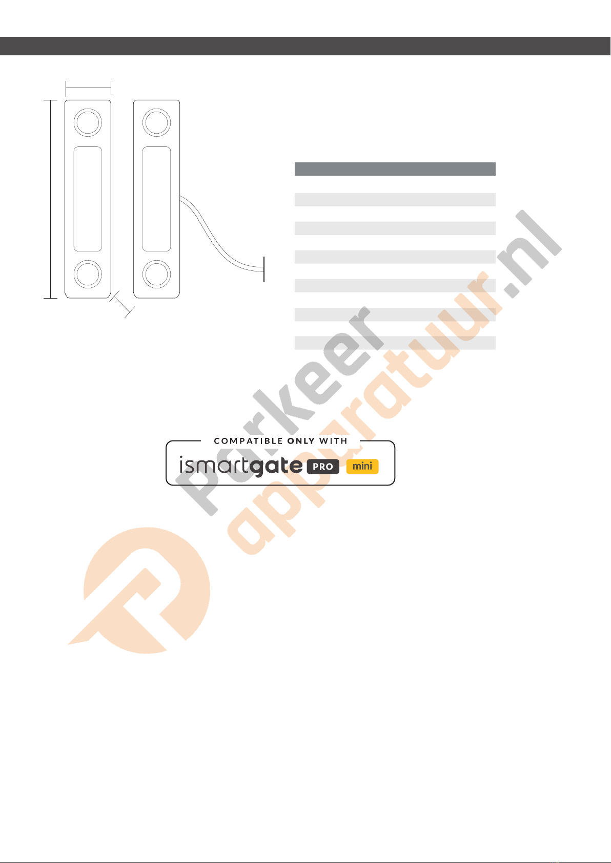
ISG-WDSSPÉCIFICATIONS
Entre -20º C et +80ºC
10 W
100 Vdc
0.5 A
1.0 A
Normalement ouvert (NO)
24# AWG avec 2 ls
ABS
1 x 10⁸fois
(IP65) Imperméable
10 mètres
3 mètres
Température de fonctionnement
Tension de contact maximale
Tension de commutation maximale
Courant de commutation maximal
Courant porteur maximal
Puissance de sortie
Fil utilisable
Matériel
Durée de vie du contact
Imperméabilité
Longueur de câble (WDS-101)
Longueur de câble (WDS-102)
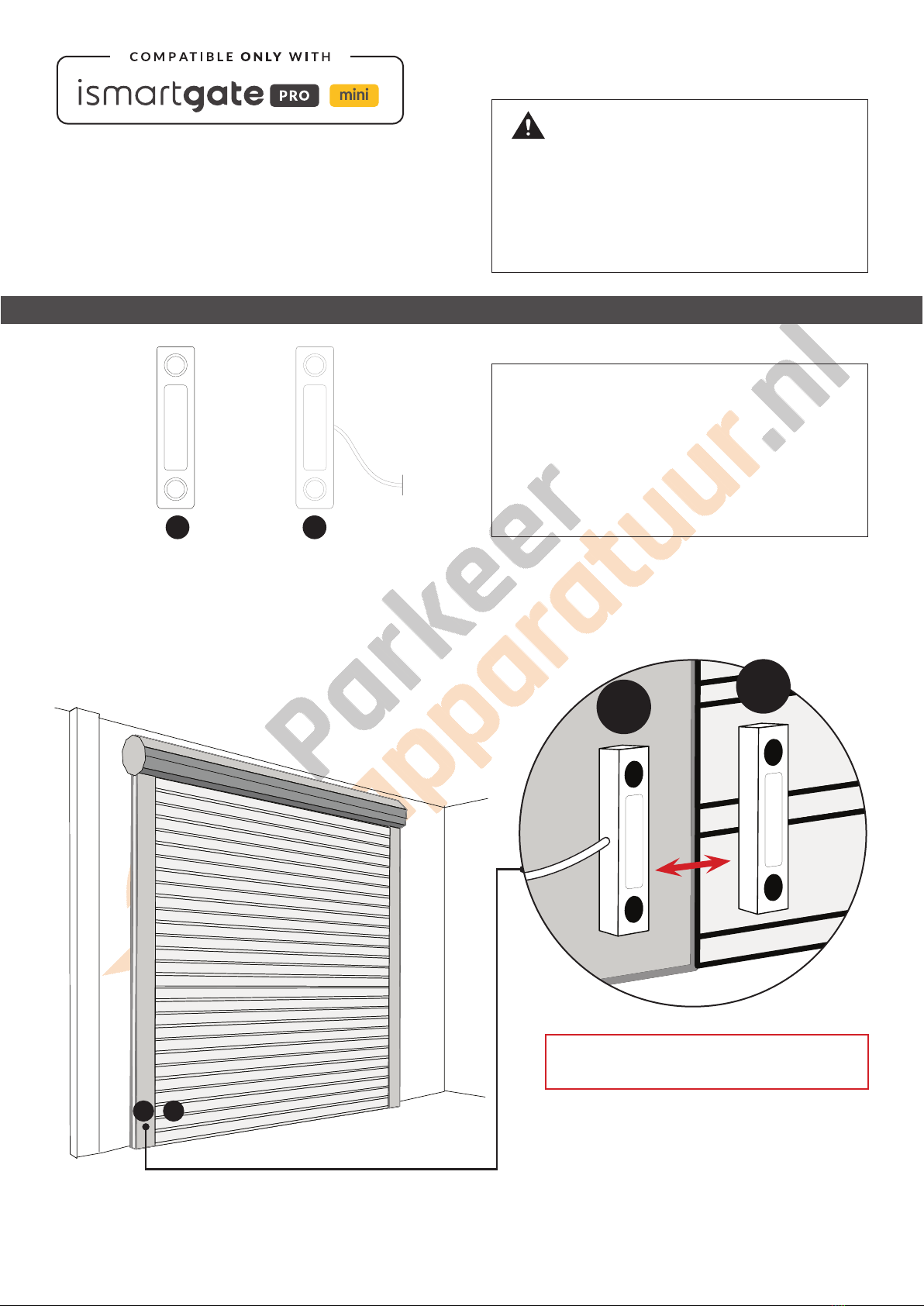
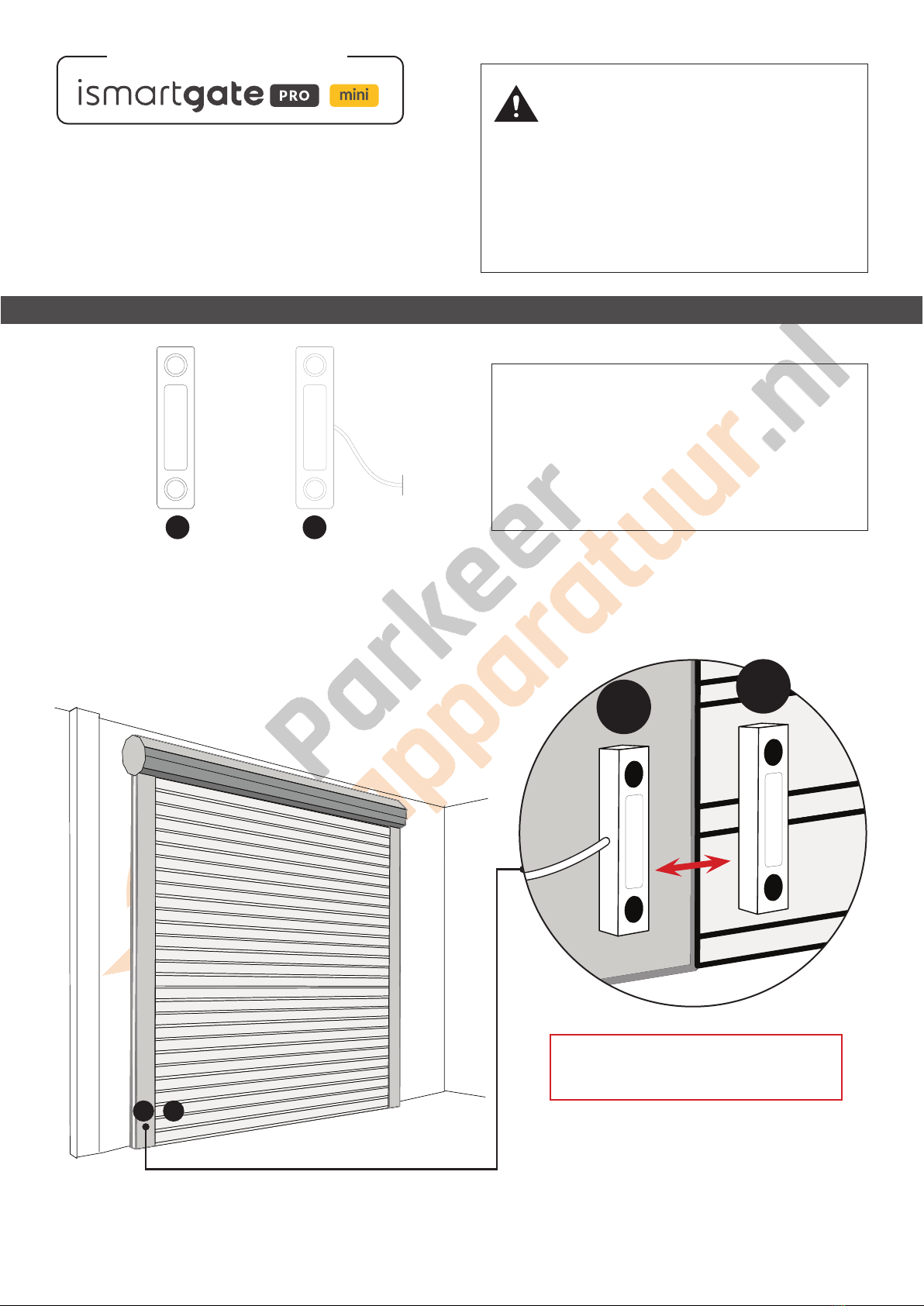
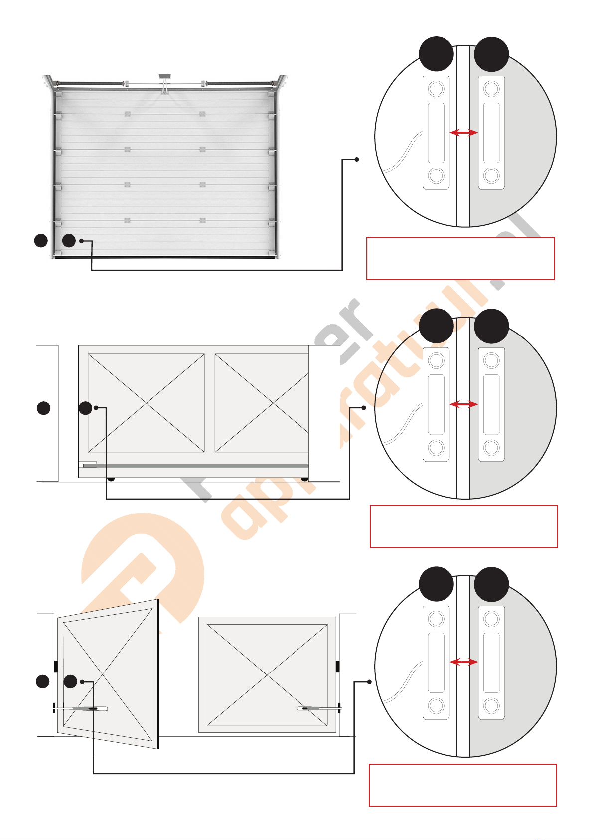
Fonctionnalités du capteur principal :
· Controler à distance si la porte de garage/portail est ouvert(e) ou fermé(e)
· Recevoir des alertes en temps réel sur votre Smartphone par e-mail
· Capteur magnétique facile à installer avec des rubans adhésifs double face
· Enregistrer tous les activités de la porte de garage/portail dans un calendrier intégré
· Idéal pour les porte de garage/portail extrêmement fréquentés (ex. plus de 10 fois par jour)
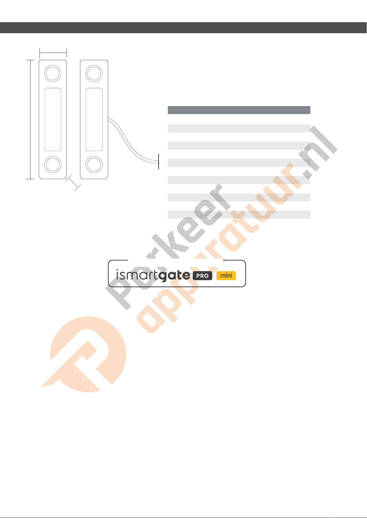
88 mm
17 mm
16 mm
SPÉCIFICATIONS
UNIQUEMENT COMPATIBLE AVEC
Regulatory notices
REMSOL has not approved any changes or modications to this device by the user. Any changes or modications could void the user’s authority to operate the equipment.
This device complies with Part 15 of the FCC Rules. Operation is subject to the following two conditions: (1) this device may not cause interference, and (2) this device must accept
any interference, including interference that may cause undesired operation of the device.
This device complies with FCCC radiation exposure limits set forth for an uncontrolled environment and meets the FCC radio frequency (RF) Exposure Guidelines. This transmitter
must not be co-located or operating in conjunction with any other antenna or transmitter.
This equipment has been tested and found to comply with the limits for a Class B digital device, pursuant to part 15 of the FCC Rules. These limits are designed to provide
reasonable protection against harmful interference in a residential installation. This equipment generates, uses and can radiate radio frequency energy and, if not installed and
used in accordance with the instructions, may cause harmful interference to radio communications. However, there is no guarantee that interference will not occur in a particular
installation. If this equipment does cause harmful interference to radio or television reception, which can be determined by turning the equipment off and on, the user is encouraged
to try to correct the interference by one or more of the following measures:
· Reorient or relocate the receiving antenna.
· Increase the separation between the equipment and receiver.
· Connect the equipment into an outlet on a circuit different from that to which the receiver is connected.
· Consult the dealer or an experienced radio/TV technician for help.
This device complies with Part 15 of the FCC Rules. Operation is subject to the following two conditions: (1) this device may not cause harmful interference, and (2) this device must
accept any interference received, including interference that may cause undesired operation.

· Lassen Sie Kinder das ismartgate-Produkt und die App NICHT ohne Aufsicht eines
Erwachsenen verwenden.
· Betreiben Sie Ihr ismartgate-Gerät NUR, wenn Sie freie Sicht auf Ihre Garage oder Ihr Tor
haben und sich vergewissert haben, dass keine Gegenstände den Betrieb des Tors behin
dern. IMMER warten, bis das Garagentor oder Tor vollständig geschlossen ist.
· Bedienen Sie NIEMALS die Fernzugriffsfunktion Ihres ismartgate, ohne sicherzustellen,
dass sich ein Erwachsener physisch vor der Tür oder dem Tor bendet, der bestätigt, dass
es sicher ist, den Fernbetrieb Ihres Geräts zu starten.
Lesen Sie die Anweisungen sorgfältig durch, bevor Sie beginnen
Bitte vergewissern Sie sich, dass Ihre Garage/Tor geschlossen ist, bevor Sie mit der Installation beginnen.
Das ismartgate-Gerät und unsere kabelgebundenen Magnetsensoren sind für die Verwendung mit
Garagen-/Torantrieben vorgesehen, die mit Lichtschranken-Sicherheitssensoren ausgestattet sind.
Diese Sensoren benden sich normalerweise unten an Ihrer Garage/Ihrem Tor und verhindern ein
versehentliches Schließen Ihres Tors, wenn sich ein Gegenstand oder eine Person auf dem Weg des Tors
bendet.
Installieren Sie Ihre kabelgebundenen Magnetsensoren immer bei geschlossenem
Garagentor oder Tor.
Bei Schiebetoren oder Garagentoren sollte Teil A am Tor/Garagentor und Teil B an der
Wand oder am festen Teil des Tors/der Garage montiert werden. Bitte stellen Sie sicher,
dass Sie den Sensor auf der Seite näher am ismartgate-Gerät platzieren.
Bei Drehtoren sollte Teil B an dem Tor montiert werden, das näher am ismartgate-Gerät
liegt. Teil A sollte auf dem anderen Tor platziert werden.
Installationsanleitung für kabelgebundene
Magnetsensoren (iSG-WDS)
A) Montage an einem Rolltor
SCHRITT 1 – PLATZIEREN SIE IHRE SENSOREN AN EINEM ROLLTOR ODER EINEM TOR
Platzieren Sie dieses Teil
am Tor / Garagentor
Platzieren Sie dieses
Teil an der Wand
Bringen Sie Ihre kabelgebundenen Magnetsensoren gemäß der Zeichnung
unten an Ihrem Rolltor an.
PLATZIEREN SIE DEN SENSOR AM UNTEREN TEIL IHRES ROLLTORS.
UM SCHWERE VERLETZUNGEN ODER TOD DURCH
DAS BEWEGEN VON GARAGENTÜREN ODER -TOR-
EN ZU VERHINDERN:
A B
A
B
STELLEN SIE SICHER, DASS DER AB-
STAND ZWISCHEN TEIL B UND TEIL A
WENIGER ALS 3 CM IST.
AB
NUR KOMPATIBEL MIT

C) Installation an einem Schiebetor
D) Montage an einem Drehtor
B) Montage an einem Sektionaltor
Bringen Sie Ihre kabelgebundenen Magnetsensoren gemäß der Zeichnung unten an Ihrem Schiebetor an.
Bringen Sie Ihren magnetischen Kabelsensor wie in der Zeichnung unten gezeigt an Ihrem Drehtor an.
Bringen Sie Ihre kabelgebundenen Magnetsensoren gemäß der folgenden Zeichnung an Ihrem Sektionaltor an.
A
A
A
B
B
B
PLATZIEREN SIE DEN SENSOR IM MITTELTEIL IHRES SCHIEBETORS.
AB
AB
AB
PLATZIEREN SIE DEN SENSOR IM ABSCHNITT UNTEN AN IHRER TÜR.
STELLEN SIE SICHER, DASS DER AB-
STAND ZWISCHEN TEIL B UND TEIL A
WENIGER ALS 3 CM IST.
STELLEN SIE SICHER, DASS DER AB-
STAND ZWISCHEN TEIL B UND TEIL A
WENIGER ALS 3 CM IST.
STELLEN SIE SICHER, DASS DER AB-
STAND ZWISCHEN TEIL B UND TEIL A
WENIGER ALS 3 CM IST.

Verbinden Sie Ihr ISG-WDS gemäß den nachstehenden Anweisun-
gen mit Ihrem ismartgate-Gerät.
Beim Anschließen von kabelgebundenen Sensoren an ein
ismartgate-Gerät spielt die Polarität keine Rolle.
WARNUNG: Wenn Sie das ismartgate zum ersten Mal mit einem kabelgebundenen Sensor kongurieren,
lesen Sie bitte unser Online-Handbuch, das Sie unter folgendem Link nden https://setup.ismartgate.com/ oder
besuchen Sie unsere Website für weitere Informationen.
Öffnen Sie die ismartgate
Zugriff App und klicken
Sie auf das Symbol
KONFIGURATION.
Wenn Sie dies noch nicht
getan haben, aktivieren Sie
bitte die Tür, die Sie mit dem
kabelgebundenen Sensor
verwenden möchten.
Wählen Sie im Menü
KONFIGURATION bitte
“Türen“ aus.
Wählen Sie im Abschnitt
“Tür”-KONFIGURATION den
kabelgebundener Sensortyp
aus.”
Scrollen Sie schließlich nach
unten und klicken Sie auf die
Schaltäche “Aktualisieren“,
um die Sensoreinrichtung in
der App abzuschließen.
SCHRITT 2 – VERBINDEN SIE ISG-WDS MIT IHREM ismartgate PRO
SCHRITT 3 – PROGRAMMIERUNG DES SENSORS WÄHREND DER ismartgate PRO-INSTALLATION
TÜR 1
TÜR 3
TÜR 2

1. Gehen Sie zu den
ismartgate-Einstellungen
3. Wählen Sie den Sensortyp aus2. Wählen Sie die Option Türen 4. Wählen Sie Verkabelt 5. Wählen Sie nun die Option
Aktualisieren
SCHRITT 2 – VERBINDEN SIE ISG-WDS MIT IHREM ismartgate MINI
SCHRITT 3 – PROGRAMMIERUNG DES SENSORS WÄHREND DER ismartgate MINI-INSTALLATION
TÜR 1
Verbinden Sie Ihr ISG-WDS gemäß den nachstehenden Anweisun-
gen mit Ihrem ismartgate-Gerät.
Beim Anschließen von kabelgebundenen Sensoren an ein
ismartgate-Gerät spielt die Polarität keine Rolle.
WARNUNG: Wenn Sie das ismartgate zum ersten Mal mit einem kabelgebundenen Sensor kongurieren,
lesen Sie bitte unser Online-Handbuch, das Sie unter folgendem Link nden https://setup.ismartgate.com/ oder
besuchen Sie unsere Website für weitere Informationen.

ISG-WDSSPEZIFIKATIONEN
Zwischen -20º C und +80ºC
10 W
100 Vdc
0.5 A
1.0 A
NEIN (normalerweise offen)
24# AWG mit 2 Kabel
ABS
1 x 10⁸mal
Wasserdicht (IP65)
10 meter
3 meter
Betriebstemperatur
max. Kontaktbewertung
max. Schaltspannung
max. Schaltstrom
max. Strom tragen
Ausgabe
Verwendbarer Kabel
Material
Kontakt Leben
Undurchlässigkeit
Kabellänge (WDS-101)
Kabellänge (WDS-102)
Hauptmerkmale des Sensors:
· Überwachen Sie aus der Ferne, ob die Garage/das Tor offen oder geschlossen ist
· Erhalten Sie Echtzeit-Benachrichtigungen auf Ihrem Smartphone oder per E-Mail
· Einfach zu installierender Magnetsensor mit doppelseitigem Klebeband
· Verfolgen Sie alle Garagen-/Torereignisse in einem integrierten Veranstaltungskalender.
· Ideal für Garagentore und -tore mit hohem Verkehrsaufkommen (z. B. über 10 Zyklen pro Tag).
88 mm
17 mm
16 mm
SPEZIFIKATIONEN
NUR KOMPATIBEL MIT
Regulatory notices
REMSOL has not approved any changes or modications to this device by the user. Any changes or modications could void the user’s authority to operate the equipment.
This device complies with Part 15 of the FCC Rules. Operation is subject to the following two conditions: (1) this device may not cause interference, and (2) this device must accept
any interference, including interference that may cause undesired operation of the device.
This device complies with FCCC radiation exposure limits set forth for an uncontrolled environment and meets the FCC radio frequency (RF) Exposure Guidelines. This transmitter
must not be co-located or operating in conjunction with any other antenna or transmitter.
This equipment has been tested and found to comply with the limits for a Class B digital device, pursuant to part 15 of the FCC Rules. These limits are designed to provide
reasonable protection against harmful interference in a residential installation. This equipment generates, uses and can radiate radio frequency energy and, if not installed and
used in accordance with the instructions, may cause harmful interference to radio communications. However, there is no guarantee that interference will not occur in a particular
installation. If this equipment does cause harmful interference to radio or television reception, which can be determined by turning the equipment off and on, the user is encouraged
to try to correct the interference by one or more of the following measures:
· Reorient or relocate the receiving antenna.
· Increase the separation between the equipment and receiver.
· Connect the equipment into an outlet on a circuit different from that to which the receiver is connected.
· Consult the dealer or an experienced radio/TV technician for help.
This device complies with Part 15 of the FCC Rules. Operation is subject to the following two conditions: (1) this device may not cause harmful interference, and (2) this device must
accept any interference received, including interference that may cause undesired operation.
Table of contents
Languages: