ii www.teejet.com
IC18 Sprayer/NH3 OEM options
Table of Contents
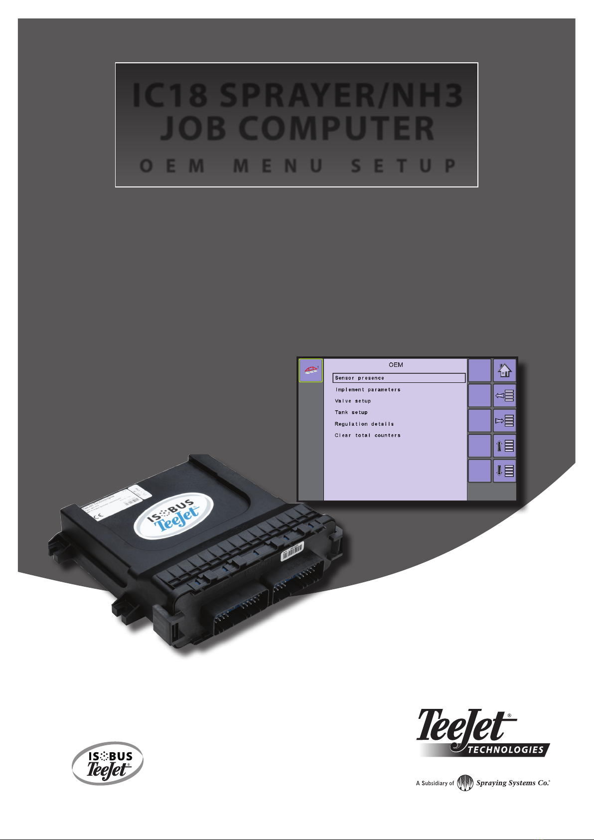
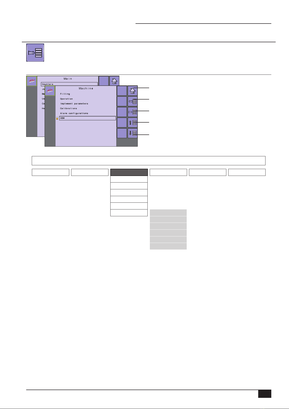
OEM SETUP OPTIONS 1
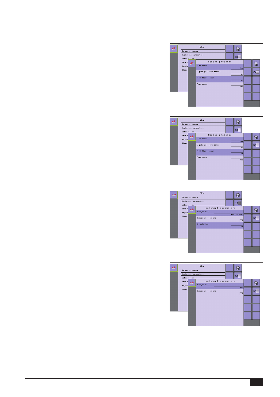
Sensor Presence ..................................................................................................................................................................................... 3
Flow Sensor...........................................................................................................................................................3
Liquid Pressure Sensor..........................................................................................................................................3
Fill Flow Sensor (Sprayer Mode) ...........................................................................................................................3
Tank Sensor (Sprayer Mode).................................................................................................................................3
Implement Parameters........................................................................................................................................................................ 3
Sprayer Mode ........................................................................................................................................................3
Number of Sections ...............................................................................................................................................3
Circulation (Sprayer Mode)....................................................................................................................................3
Valve Setup .............................................................................................................................................................................................. 4
Regulation Valve Type ...........................................................................................................................................4
Section Valve Behavior..........................................................................................................................................4
Section Valve Type (Sprayer Mode).......................................................................................................................4
Tank Setup................................................................................................................................................................................................ 4
Maximum Content..................................................................................................................................................4
Minimum Content...................................................................................................................................................4
Auto Filling (Sprayer Mode) ...................................................................................................................................4
Auto Filling Offset (Sprayer Mode).........................................................................................................................4
Regulation Details ................................................................................................................................................................................. 5
Minimum Regulation Pressure...............................................................................................................................5
Maximum Regulation Pressure..............................................................................................................................5
Regulation Valve Time ...........................................................................................................................................5
Minimum Regulation Voltage .................................................................................................................................5
Regulation Dead Band...........................................................................................................................................5
Regulation Backlash ..............................................................................................................................................5
Anticipation Factor .................................................................................................................................................5
Default Valve Position............................................................................................................................................5
Regulation Valve Capacity.....................................................................................................................................5
Regulation Start Delay...........................................................................................................................................6
Minimum Speed.....................................................................................................................................................6
Manual Regulation Speed......................................................................................................................................6
Restrictor Plate Flow (Sprayer Mode)....................................................................................................................6
Clear Total Counters.............................................................................................................................................................................. 6
Area .......................................................................................................................................................................6
Volume...................................................................................................................................................................6
Time .......................................................................................................................................................................6
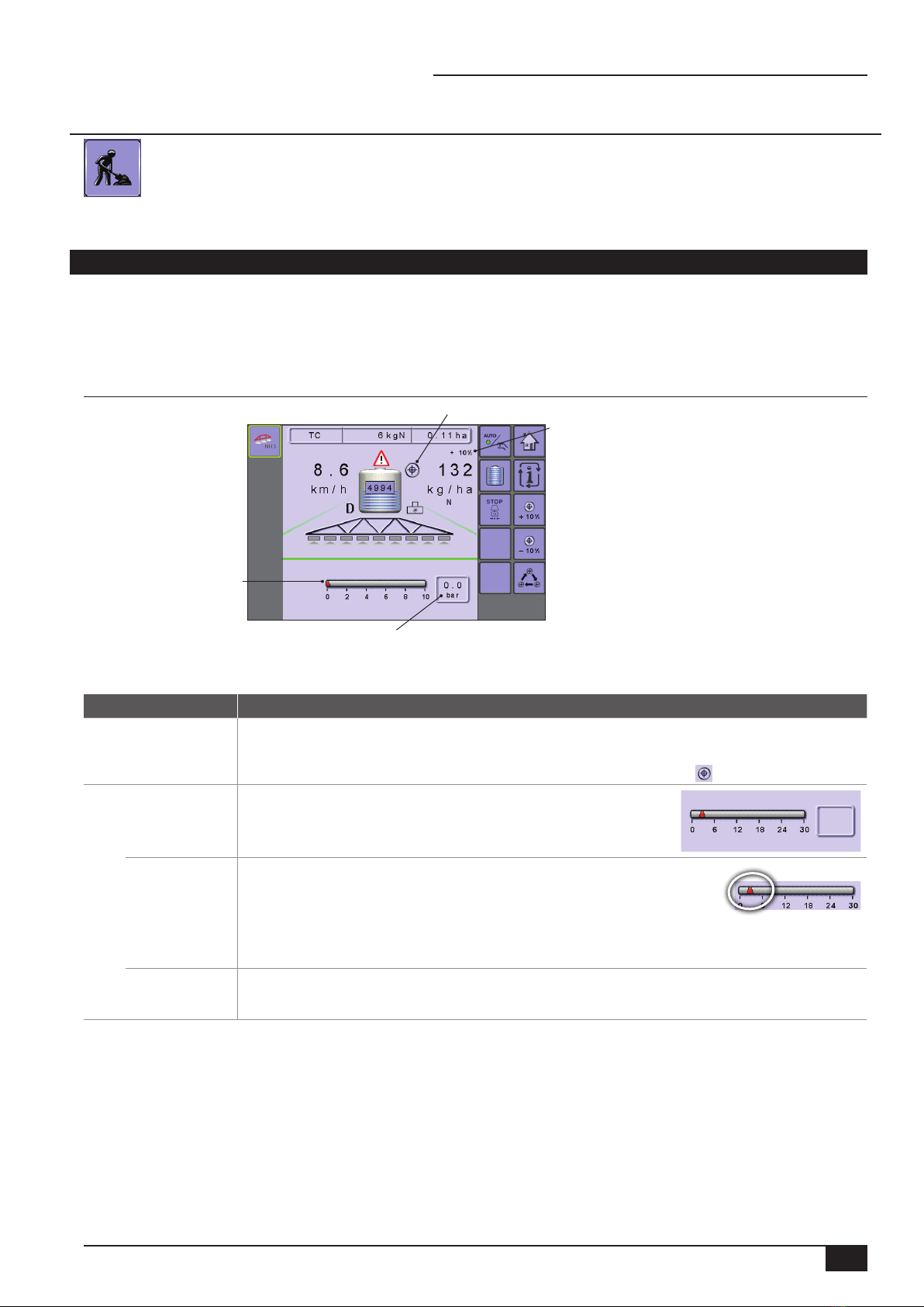
CHANGES ON OPERATION SCREEN 7
LIQUID PRESSURE SENSOR ACTIVATED (NH3 MODE) 7
Operation Mode Overview ................................................................................................................................................................ 7
Section and Icon Descriptions .........................................................................................................................................7
Application Rate Options.................................................................................................................................................................... 8
Target Rate Percentage Increase/Decrease....................................................................................................................8
Target Rate ......................................................................................................................................................................8
With Switchbox ......................................................................................................................................................8
Without Switchbox .................................................................................................................................................8