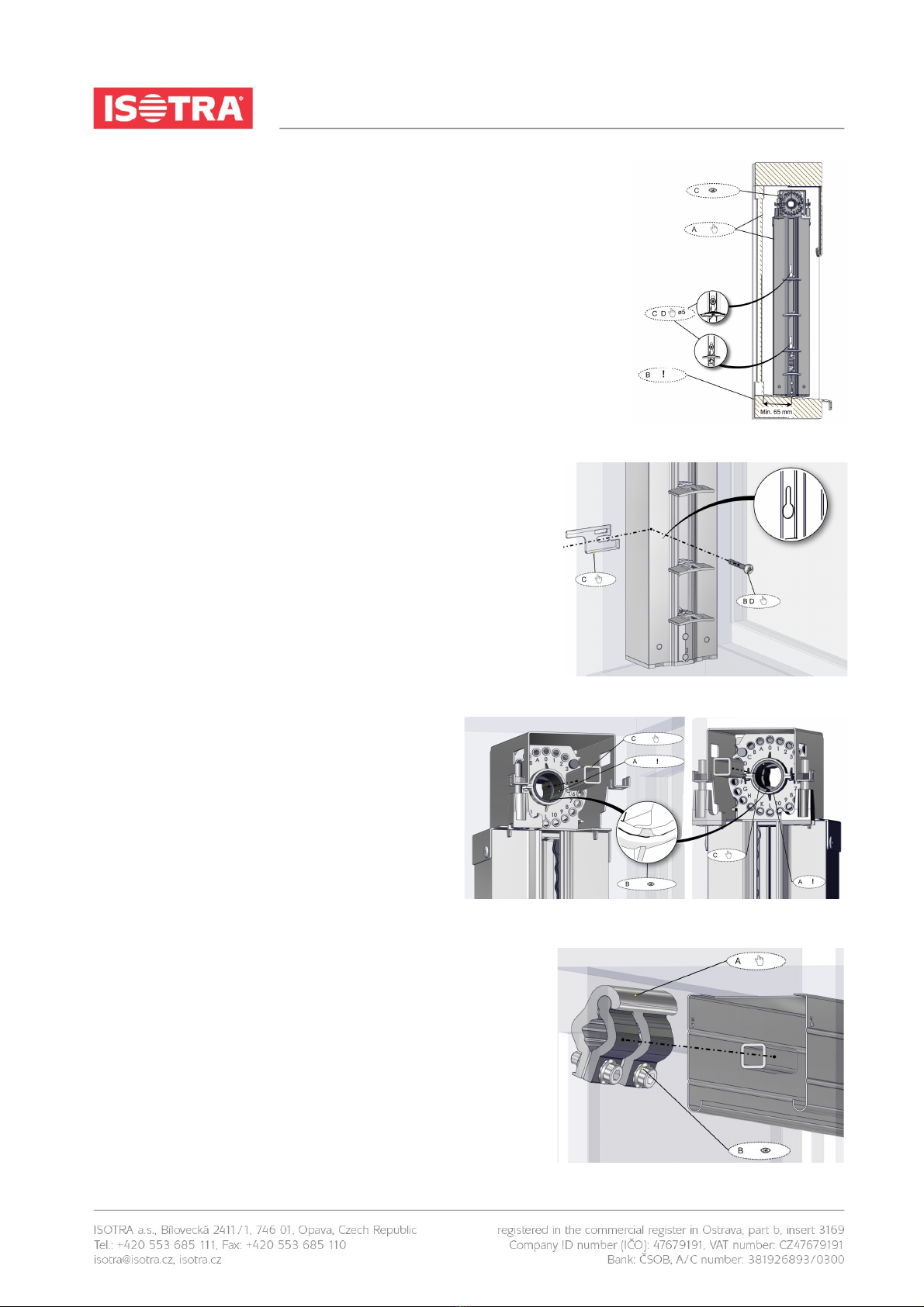
2.5.1. Guiding rails assembly
A – Level the rail into lining.
B – Minimal distance between guiding rail axis and the obstacle is 65mm.
C – Mind the difference between left and right guiding rail, place them correctly.
D – Make marks through the assembly holes for using suitable fixing elements.
E – Screw and insert fixing elements.
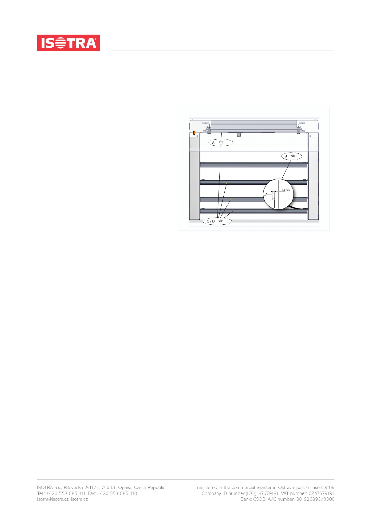
2.5.2. Guiding rails attachment
A – Check that you have not misplaced right and left rail.
B – Screw the screws through the guiding rail.
C – Before tightening put the distance pad on the screw between lining
and the rail.
D – Tighten the screws and check the level of rails again.
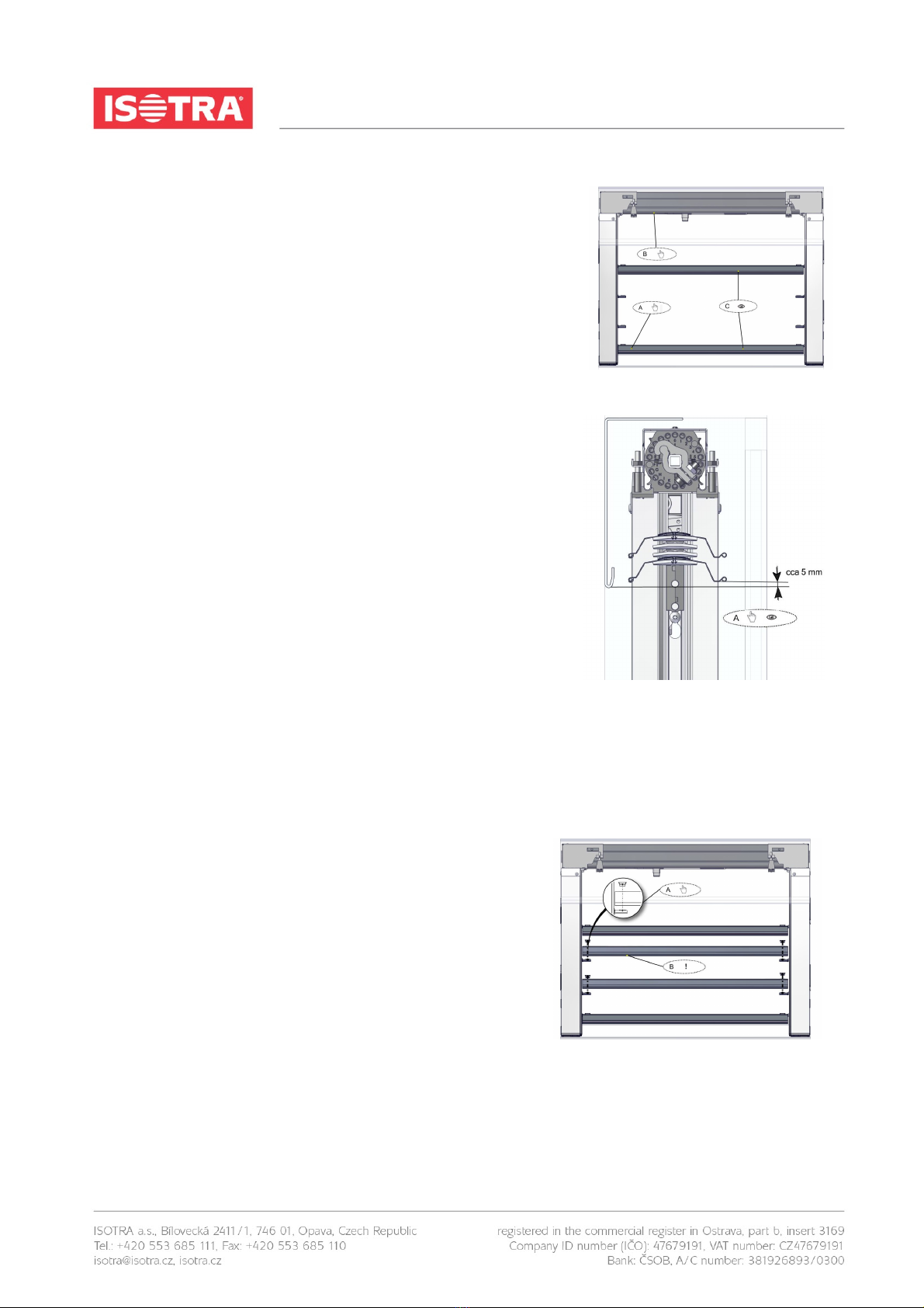
2.5.3. Check the bearing position
A – Do not turn the bearing in any case. Default setting
can be lost.
B – Ensure that bearing marking are facing down on
both guiding rails.
C – Insert short connection shafts into the bearings.
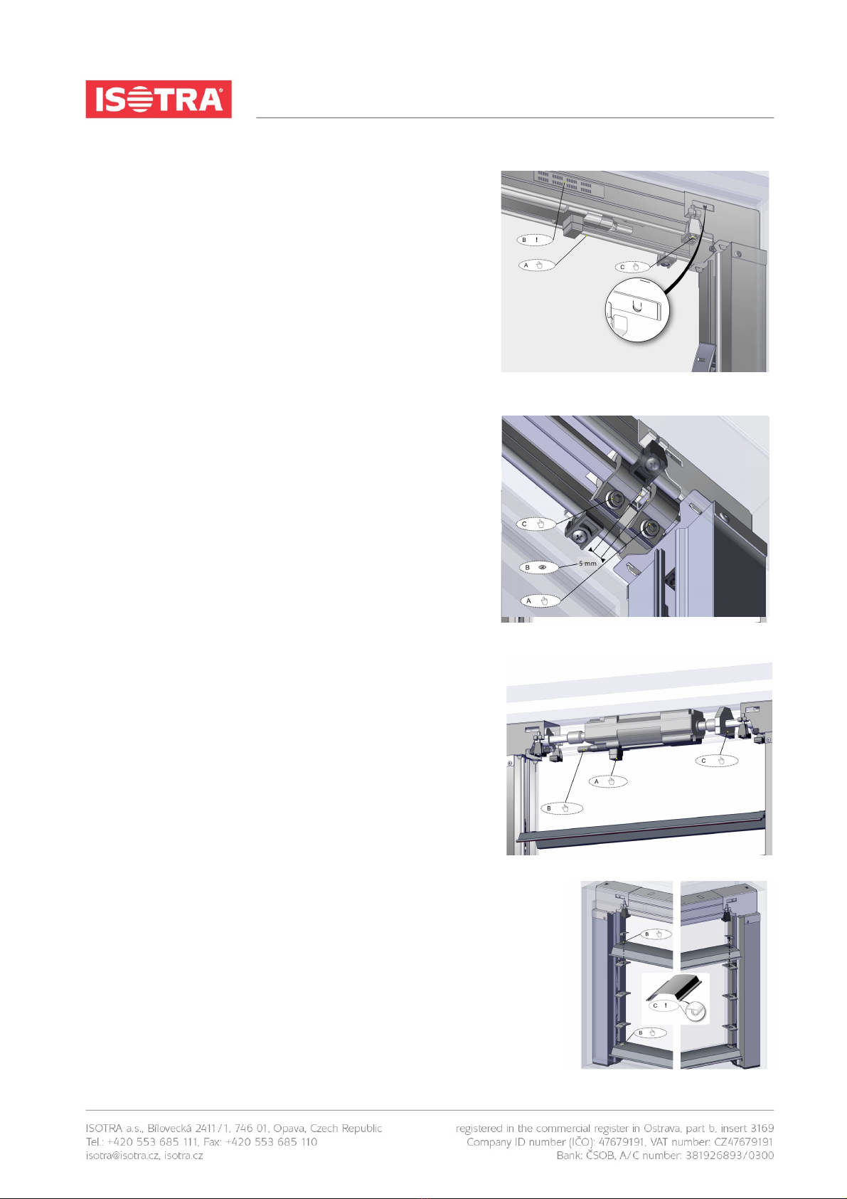
2.5.4. Head-rail with engine - preparation
A – Slide the connectors onto four-square shaft into the head-rail. One
from the left and one from the right side.
B – Screw heads are facing always down.