3.
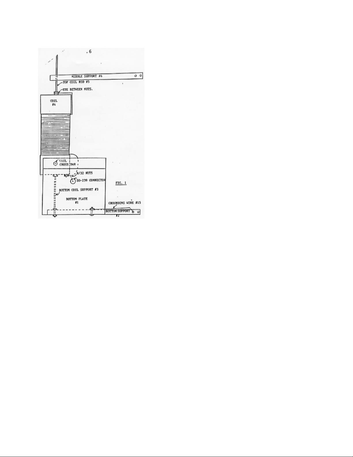
5. Attach the wire pigtail from the SO-239 Connector and
the wire pigtail from the bottom of COIL #4 to the 8/32
stud at the bottom of the coil. Remove one nut, put the
solder lugs on and replace the nut and secure. See Fig. 1
and 5.
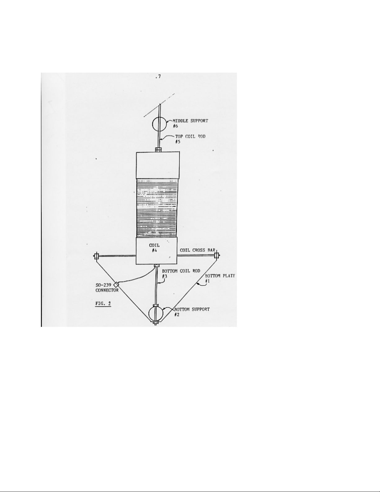
6. Put one nut on one end of the TOP COIL ROD #5. Put
this
threaded end through the wire eye at the top of the COIL.
Attach a second nut, then screw the TOP COIL ROD #5
into the COIL. With the threads most of the way into the
coil, tighten the nut against the coil, then tight the nut
above the wire eye. See Fig. 1 and 3.
7. Slide the MIDDLE SUPPORT #6 on to the TOP COIL
ROD #5. Use the single hole at the end of the support.
This support will be at 1" above the adjacent nut on the
COIL.
8. At the opposite end of the 30" rod that is screwed into
the coil, screw a 1/4" nut about 1/2 way down on the
threads. Next screw the 1/4" x 7/8" coupling nut so it is
against the standard nut. Snug these 2 nuts together. Set
this section aside and go to the top section for assembly.
9. Slide TUNING ROD BRACKET #9 onto the second TOP
COIL ROD #5, leave it loose. Set this aside. See Fig. 3.
10. Attach the TOP PLATE #11 to TOP SUPPORT #13.
Use a 1/4" x 1 1/2" Bolt with a nut in the hole closest to
the mast, but do not secure. See Fig. 3.
11. Slide the second TOP COIL ROD #5 through the
U-JOINT #10. If needed you can loosen the set screw, but
re-tighten once everything is in place. See Fig. 3
12. Slide the second TUNING ROD BRACKET #12 on to
the TOP COIL ROD #5. See Fig. 3.
13. Thread a 1/4" nut all the way down on the top of
second TOP COIL SUPPORT #5. Then add a flat washer
from the hardware packet, then slide into the hole
attaching the TOP SUPPORT #13 and TOP PLATE #11.
Secure with a second nut, but leave it loose. Secure the 1
1/2 " Bolt previously installed in step #11. See. Fig. 3.