iSP Beta Bass User manual


INTRODUCTION
Congratulations on your purchase of the Beta Bass Pedal. The Beta Bass Pedal was designed to
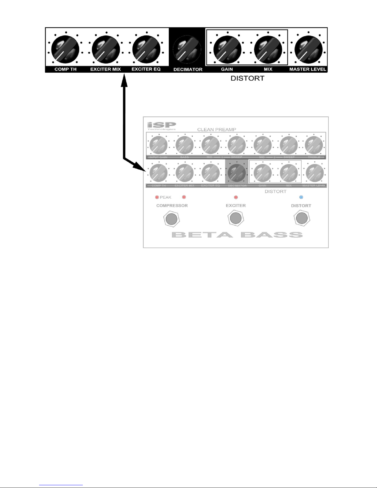
provide professional performance in a floor foot pedal. With a bass, treble plus two semi
parametric mid band EQ circuits, studio compression, Bass Exciter, Bass Distortion plus on board
Decimator II G-String noise reduction system. The Beta Bass Pedal can be used to drive your
stage rig and also offer a balanced direct output (post processing) for direct recording or to feed
front of house. Please read this manual carefully for a through explanation of the Beta Bass
Pedal and its functions.
IMPORTANT SAFTEY INSTRUCTIONS
Please read the following very carefully before operating this unit
Read ALL instructions carefully before using this unit. Keep these instructions for future reference.
Heed all warnings and follow all instructions.
Do not use this unit near water, in the rain, or where there is moisture. If this warning is ignored a
serious electrical shock or death may occur.
Do not attempt to service this unit. No user serviceable parts inside. Refer servicing to qualified,
ISP approved personnel. Servicing is required when the unit is damaged in any way, such as power
adaptor is damaged, liquid has been spilled into the unit, the unit has been exposed to rain or
moisture, does not operate normally, or has been dropped.
Care should be taken to avoid to spill any foreign objects or liquid into this unit. Avoid exposure of
this equipment to dripping or splashing and ensure that no objects filled with liquid, such as vases,
are placed on the equipment.
Only use accessories or attachments that are specified by the manufacturer.
Failure to follow these instructions may void the warranty.
NO USER SERVICABLE PARTS INSIDE. REFER SERVICING TO QUALIFIED ISP
TECHNOLOGIES SERVICE PERSONNELL.
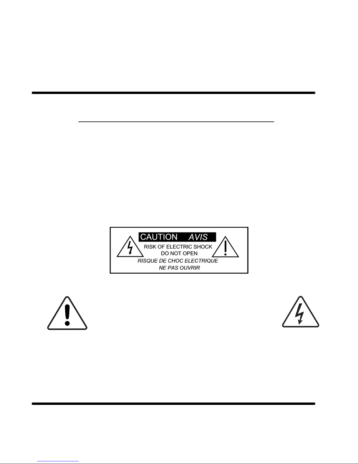
The lightning bolt triangle is used to alert the user to the risk of electric shock.
The exclamation point triangle is used to alert the user to important operating or
maintenance instructions.
POWER REQUIREMENTS
This unit requires the connection of the external AC Power Adaptor to a 120 volt AC outlet.
Do not attempt to connect this unit to any power source other than the specified 120VAC.
The Beta Bass Pedal will typically draw approximately .5 amps of current.

BETA BASS PEDAL CONTROLS
The upper row of controls are for the clean preamplifier. The lower row of controls are
for the Compressor, Exciter, Decimator Noise Reduction and Distortion Circuit. Three
footswitches are provided with the first footswitch allows the player to select Compressor
ON / OFF. The second footswitch switches ON and OFF the Bass Exciter. The third
footswitch switches ON and OFF the Distortion circuit.
BETA BASS PEDAL REAR PANEL
The rear panel has two ¼ inch phone jacks with one for the Bass Guitar input, one for
the final output signal. The Power Jack is connected to the supplied 9VAC power
adaptor. The Beta Bass pedal internally converts the 9 volt AC signal from the power
adaptor to a professional +/- 15 volt DC power supply. This allows a 30 volt internal
signal swing required for proper headroom and professional level performance. The
BETA BASS pedal will only operate on a 9VAC power source, do not use any other
power adaptor or damage may result. A balanced XLR output is also provided for
direct output to a mixer or a professional power amplifier input.

UNDERSTANDING THE BETA BASS PEDAL
The Beta Bass Pedal runs on an external 9VAC power adaptor and internally multiplies
the 9VAC to produce a +/- 15 volt power supply. This means the Beta Bass provides true
professional internal headroom not a typical 9 volt DC swing of other Bass guitar pedals.
The input signal is buffered and connected to the input of the clean PREAMP. The clean
preamp includes an input gain block to trim the Bass Guitar level so as to avoid
overdriving the Beta Bass Pedal at any point in the signal chain, a shelving bass and
treble control and dual mid frequency semi parameteric equalizers which includes a
boost/cut control plus frequency sweep, which will be described in more detail in the
PREAMP section. The output of the EQ section feeds the input of the Exciter circuit
followed by the Distortion circuit followed by the Decimator / Compression VCA and then
the Master Output Level. The Compression and Decimator level detection circuits are
reading the direct Bass Guitar Input which allows the Decimator to function like our G
String pedal. This means adjustements in the EQ, EXCITER COMPRESSOR and
DISTORTION will not require any adjustment of the Decimator Threshold control. You
can also switch ON and OFF these functions without any need to adjust the noise
reduction threshold. The Bass Exciter is a phase manipulation Exciter which allows
subtle mid-range shaping to help ehnance the midrange and provide extra separation of
the Bass from other instruments. The Compression circuit is designed to provide
amazingly smooth compression and keeps a consistant Bass level without squashing the
dynamics. The compression circuit is designed to provide “MAKE UP GAIN”when using
compression. This brings the final output level up based on the amount of compression
or gain reduction being used. The Distortion circuit allows a MIX between the clean
preamp output and a Bass Distortion circuit. This allows the player to add subtle crunch
to full blown distortion based on player prefference. The Master output Level controls
both stage level via ¼ ouptut and Balance Output to feed a front of house mix.
Beta Bass Block
Digram

PREAMP CIRCUIT
PREAMP CIRCUIT
The Preamp Circuit is always active and allows for the core instrument tone shaping.
INPUT GAIN
The Input Gain is right after the input buffer and is used to set the proper input level
for the Beta Bass Pedal to keep the best possible headroom and noise floor performance.
Connect the Bass Guitar to the input and adjust the Input Level control until the PEAK led
above the COMPRESSOR switch flashes on transients or loud playing. The PEAK circuit
monitors the entire signal chain and will indicate clipping at any point in the signal chain.
Increases in EQ or Exciter will increase the signal chain level and requires that the Input
Level be turned down to avoid clipping of the instrument signal. Once all adjustments
are made for all other controls re-adjust the Input Level so the PEAK LED only flashes on
extreme transients and does not stay lit under normal playing.
BASS
This control adjusts the amount of boost or cut in the low frequency portion of the
spectrum of PREAMP. The available BASS boost and cut range is +/- 15 decibels.
Note: the Bass control is flat when the control is centered at 12:00.

MIDRANGE BOOST/CUT CONTROL 1 AND 2
This control works in conjunction with the SWEEP frequency control. The MID and
SWEEP controls work together to provide a semi-parametric tone control. When the
MID control is set at 12:00 straight up there is no boost or cut in the MID frequency
portion of the spectrum. The graph below shows the response of the MID boost/cut
and SWEEP controls. The MID control allows +/- 12db of boost or cut to be applied
at the frequency determined by the SWEEP control.
SWEEP FREQUENCY CONTROL
This control works in conjunction with the MID boost/cut control and adjusts the
center frequency of the MID boost or cut signal. At the full counter clockwise setting
the midrange 1 frequency will be at 60Hz, at the full clockwise setting the center
frequency of the midrange will be at 1.2KHz. Midrange 2 will sweep from 250HZ to
6KHZ. NOTE: when the MID control is set at 12:00 straight up the SWEEP will not
have any effect on the signal since there is no boost or cut being applied.
TREBLE CONTROL
The TREBLE control adjusts the boost or cut that is applied in the high frequency
portion of the spectrum of the PREAMP. The available TREBLE boost and cut range is
+/- 15 decibels.

COMPRESSION THRESHOLD CONTROL
Adjusts the amount of compression and simultaneously adjusts the amount of makeup
gain in the compression circuit. The Compressor has a varying ratio that changes
based on the amount of compression being applied.
EXCITER MIX
Adjusts the amount of Exciter signal mixed in the signal path.
EXCITER EQ
Adds and subtracts midrange and high frequencies to add transparency by altering
the harmonic structure of the signal.
DECIMATOR CONTROL NOISE REDUCTION CONTROL
The DECIMATOR control adjusts the THRESHOLD of the Decimator G-String II. The
Decimator works with both the Clean PREAMP and the DISTORT circuit and will switch
completely out of the signal path when both the PREAMP and DISTORT circuits are
switched off. If either the PREAMP or DISTORT circuits are switched on the
Decimator circuit will be automatically switched into the signal path. The DECIMATOR
noise reduction is a low level downward expander incorporating ISP’s patented TIME
VECTOR PROCESSING. The Decimator is covered under multiple patents including
6,944,305, 7,532,730 and 7,957,546 with other patents pending.

A BRIEF EXPLANATION OF THE DECIMATOR NOISE REDUCTION SYSTEM
Low Level Downward Expansion is performed by use of a high quality voltage
controlled amplifier controlled by an RMS based audio level detection circuit. A Time
Vector Processing circuit is used which varies the release response over a 1000 to 1
ratio and controls the release response of the Downward Expander. The release
response will be extremely fast, about 2 milliseconds, if the input signal has a fast
decaying envelope, and upwards of 2 seconds if the input signal has a slow decay.
Downward Expansion takes place when the input signal level drops below the preset
threshold. For example, if the threshold is set for 0db an input signal of 0db will
produce no expansion. As the input signal drops below 0db, downward expansion
starts and increases exponentially the farther the input signal drops below the
threshold point. The figure below shows the response of the Expander with a 0db
threshold.
SETTING THE DECIMATOR THRESHOLD
Start by setting the Threshold for minimum, full counterclockwise. Turn the Threshold
control clockwise until the desired effect of the downward expander is achieved. The
expander should start to operate when there are gaps in the audio or as the input
signal gets close to the noise floor. NOTE: Setting this control to high will cause the
expander to start to cut off the input signal to soon.
DISTORT GAIN
Adjusts the gain in the distortion clipper circuit from 3db to over 50db.
DISTORT MIX
Adjusts the amount of distortion mixed in with the non-distorted signal. In the full
counterclockwise setting, no distortion is added, at 12:00 setting the mix will be 50%
clean and 50% distortion and full clockwise the mix is 100% distortion.
MASTER LEVEL
Adjusts the output level of both the ¼ inch output jack and the XLR balanced line
output.

BETA BASS SPECIFICATIONS
Input Impedance
Maximum Input Level
Maximum Output Level
Bass Treble Cut Boost Level
Low/Mid parametric frequency range
High/Mid parametric frequency range
Compression Section
Decimator Noise Reduction
Power Requirements
Current Draw
Dimensions
500K ohms
+20dbu typical
+20dbu typical
+/- 15db
60Hz-1kHz
200Hz-6kHz
Based on Time Vector Processing
adaptive response auto makeup gain.
Greater than 80db
9V AC 1000ma
865mA
19” x 6” x 1¾”
WARRANTY AND SERVICE
The Internal Circuitry is fully guaranteed to be free of defects under normal use and service for a
period of three years from the date of purchase.
Any damage resulting from the misuse or the failure to follow the precautions and instructions will
void the warranty.
In the event that the unit needs to be repaired, please return the unit to ISP Technologies directly.
Simply repack the unit, send a copy of the original receipt, a note stating the problem, your
contact information and send it to:
ISP Technologies, LLC
5479 Perry Drive Suite B
Waterford, MI 48329
Attn: Repair Dept.
All shipping charges must be fully prepaid.
ISP will not be responsible for any damages incurred in shipping of any unit. Any claim will need
to be settled with the shipping company.
The warranty will be voided if the serial number has been tampered with in any way. The
warranty card must also be filled out and returned in order to activate the warranty.
Should you have any questions for the repair department prior to returning the product please call
248-673-7790
ISP TECHNOLOGIES, LLC
5479 PERRY DRIVE UNIT B
WATERFORD, MI. 48329
Phone: 248-673-7790 www.isptechnologies.com
Table of contents
Other iSP Music Pedal manuals
Popular Music Pedal manuals by other brands

Mesa/Boogie
Mesa/Boogie Three Channel Dual & Triple Rectifier Solo... owner's manual

Dunlop
Dunlop VOLUME (X)8 All-in-One Quick Start Guide

DingoTone
DingoTone Limited Signature HZD Boost Laurie quick start guide

Donner
Donner Sweet Juice owner's manual

MORLEY
MORLEY AERES manual

Fortin Amplification
Fortin Amplification Fuzz manual