Lockable aluminium freestanding goal posts that are easy to move around use and store. Crossbar corners are welded both internally and externally to ensure they will stand up to the most rigorous
conditions. Oil and clean the lock to ensure the keys are working well at all times. If a key breaks inside the lock a local locksmith will be able to remove it with a special pick. Spare keys are locks are
always available. At the end of the season when the goals are not in use check all welds to ensure they have not become damaged. Check periodically through the season that the goals have not been
damaged especially if they are left up in areas prone to vandalism. When installing your goals take your time and do a good job to ensure the best results and performance. The installation guides need
to be read carefully prior to fixing. Visit itsagoal.net if you need any advice or help or contact the office. To protect the life of your paintwork we suggest that 50mm wide plastic stretch tape be wrapped
around the base of the posts about 600mm up from the ground to protect the paintwork from goal keepers kicking the foot of the posts to clean boots. This tape can be purchased from our web site or
any local DIY store and should be renewed as and when required. It is much better however if you can ask all visiting and home goal keepers not to kick the posts. A thorough inspection each year and
when goals are installed should be carried out and recorded. A goal post maintenance sheet is available to be down loaded from our web site www.itsagoal.net . Problems should be recorded, noted
down and acted upon straight away. NEVER USE DAMAGED GOAL POSTS. Goals need to be treated and handled with care and they will then last longer and will perform better. Any paint chips need to
be repaired as soon as possible. Rub down with emery paper to form a smooth surface down to bear metal and apply a good quality aluminium primer undercoat and then a top coat to seal the affected
area. Any areas left untreated will allow water to penetrate between the powder coat finish and the base metal and if left un checked the paint work will start to peel away. Any local DIY store will supply
what you need. If you treat the goalposts with respect and maintain them properly they will perform year after year.
Multi-surface anchors
Multi-surface anchors are designed to secure the freestanding goalposts to normal grass surface
pitches (to 1100 Newtons forward pull test). On a grass surface, use the ground pegs provided in
conjunction with the multi-surface anchors. If ground is softer then more ground anchors can be
used to spread the load or longer pegs can be inserted. Always angle the pegs as shown on the tting
instructions. To remove stubborn pegs use another peg to lift out do not pull out with the anchor itself
or it may damage the securing cross holding the peg in place. This is strong system designed to twist
under stress and will not easily be damaged. If you are planning to anchor your goal post on tarmac
the xing positions for the multi- surface anchors need to be secure. We advise :-
1. Dig holes in your tarmac (to sizes specied in tting instructions ).
2. Fill holes with concrete, and drill two 14mm holes 12cm apart and 70mm depth.
3. Position goal and multi-surface anchors and use a suitable10mm concrete bolt instead of the
safety grass pegs. For other surfaces such as wooden sports hall oors wood screws in our multi-
surface anchor or counter balance weights can be used. The total weight to conform to the current
standards for the goal post topple test can be calculated using the equation stated below.
Goalpost Nets
All our square mesh nets are made to the shape of the net. If you are putting nets up each week we
recommend that you locate the top corners rst and mark them using tape so that you can easily
identify them each time. Place the net over the frame and t each end onto top stanchion by securing
on each corner of the crossbar and uprights using twist and lock net xings.
We recommend only nets with 100mm x 100mm mesh be used with children, to cover head
entrapment regulations, Nets with 120mm x 120mm mesh are acceptable for use by adults.
Nets can be tied into a bundle and placed into a pillow case (not to damage washing machine)
and washed at 40 degrees Celsius with normal washing powder to keep them in tip top condition.
Be aware rabbits and rodents have been know to nibble at the base of nets. If nets are left outside
we advise lifting from ground level. If you have this problem sprinkle pepper along the bottom of the
net and this should help deter most wild animals.
Counter balance weight system
The ITSA GOAL posts counter balance weight system consists of two counter balance weights each weighing 11kgs fastened together, 22 kilos of counterweight spread over 500mm. The counter
balance weight system is used on at level playing surfaces or where multi-surface anchors can not be used i.e. sports halls, articial grass pitches etc. The two connected weights together can be
lifted on the frame and used externally. If anchoring your freestanding goalpost is not possible, the guidance and technical notes set out by the Football Association give clear instructions for the use of
counter balance weights. If you are unsure what weight you are required to use on your freestanding goal posts, you can work out the weight needed by using the following procedure.
1 Measure the height of the crossbar., 2 Measure the length of the goal’s side bars. 3 Divide the height by the length. Multiply the result by 112Kg and make a note of the answer. This is the total weight
in kilograms that should stabilizes the goal to safety standards.
Example: A Regulation Goal, 2.44m high with a 2.025m ground sideframe the calculation would be: 2.44 divided by 2.025= 1.205 therefore 1.205 x 112Kg = the total weight required for this goal
would be 135Kg (less the weight of the back ground bar).
The Football Association Goals for Football Guidance Notes & Technical Details
Freestanding goals will only be safe if you stabilise them properly. Always use the accessories and
anchors supplied for the purpose of anchoring a goal. The most reliable methods of stabilising
freestanding goals are:
a attaching the back bar to permanent fixing points.
b using adequate weights attached to the goals backbar.
c. adequate ground anchors
We strongly recommend you use one of these methods. The diagram on the right shows a typical
freestanding goal foundation that will give
a permanent pitch fixing. VISIT.www.itsagoal.net for up to date goal
post safety information
Socket Cap
required when not in use
Min. Depth 40mm
Max. Depth 100mm
Playing surface
Stainless-steel fixing loop
Drainage hole
500mm
500mm
Push
to
open
Test each goal post before use to satisfy yourself that you have enough counter
balance weights attached to the goal to prevent toppling.
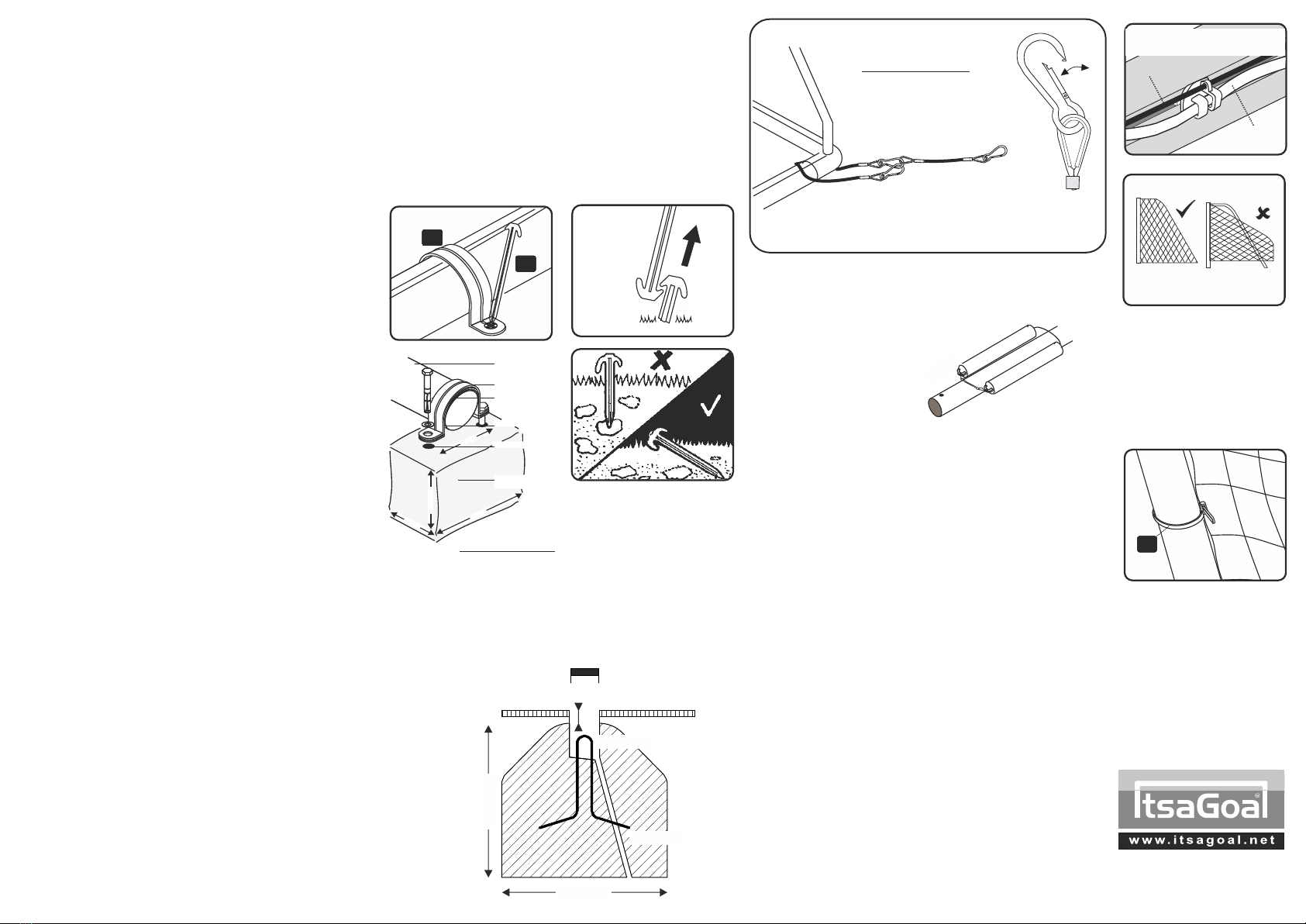
Chain and cable attachments - Whatever method is used to stabilize a goal, any
attachment chain or a wire cable between the goal and the weight, anchor, eye bolt
or other fixing point should be as short as possible and not allow the back bar to lift
more than 50 mm.
Care and Maintenance
1. NEVER use our goalposts without securing locks or correct fittings or in non
conforming ground sockets.
2. DAMAGED COMPONENTS requested under guarantee must be returned for
inspection. Failure to follow the warnings, assembly and fitting instructions
contained in this document may invalidate your guarantee.
IT IS ADVISABLE IN ANY CONTACT SPORT TO TAKE OUT THE RELEVANT
INSURANCES TO COVER ALL UNFORESEEABLE CIRCUMSTANCES. IT IS
ADVISABLE TO CHECK YOUR GOALS WEEKLY AND UNDERTAKE ANY
MAINTENANCE, CHECK PAINTWORK, CHECK NETTING, MAKES SURE ANY
LOCKS OR BOLTS ARE IN PLACE , ENSURE THE FRAME IS ASSEMBLED IN
ACCORDANCE WITH THE FITTING INSTRUCTIONS BEFORE EACH GAME. ANY
NEW PEOPLE USING THE GOALS SHOULD BE PROVIDED WITH THIS LEAFLET
AND EXTRA FITTING INSTRUCTIONS ARE AVAILABLE FROM www.itsagoal.net.
If the text is too small to read a larger easier to read copy is available upon request.
SQUARE MESH Net is cut to shape.
Simply throw over the frame and fit each
end onto top stanchion by securing on
each corner of crossbar.
NOTE: If your net does not fit the first time,
you may be fitting it to the goal frame
upside down i.e. that is to say the net from
the crossbar to the floor (a) is longer than
the length of the net to the bottom of the
upright (b).
H
OPTIONAL - STANCHION NET TIES
THREAD NET CORD INTO NET FIXINGS
INSERT SEPARATE ROD IN BETWEEN
EACH FIXING TO LOCK FIXINGS TO POST
NET CORD
OPTIONAL ROD
GROUND FRAME
WASHER
DRILL HOLE
2 x MULTI SURFACE
ANCHORS
M10 SLEEVE ANCHOR
RAWBOLT
CONCRETE BLOCK
(FOR USE ON TARMAC)
12cm(min)
30cm
12.3cm
18cm
CONCRETE BLOCK
(FOR USE ON TARMAC)
12cm(min)
30cm
12.3cm
18cm
THIS METHOD SECURELY
ANCHORS YOUR GOAL DOWN
ON TARMAC. DO NOT OVER TIGHTEN BOLT.
TWIST & LOCK Recessed Net Fixings
Fit the recessed goal net fixings into the rear
slots on the goal post sections and twist 90
degrees to secure. Position the fixings not
more than 340mm apart. The recessed net
fixings are designed to fit ITSA goal rear
slotted aluminum goal posts. When goal nets
are left attached they can also be secured
with a 4mm rod that can slide down through
the net fixings to prevent unauthorized
removal of the net fixings or goal net.
PEG
REMOVAL
J
I
LONGER GROUND PEGS ARE AVAILABLE SEPARATELY.
Longer pegs are to be used on sandy or
Soft ground earth. A risk assessment of soil
conditions suitability should be carried out when
anchors are to be used.
STEEL COUNTER BALANCE WEIGHTS
For use indoors or on artificial surfaces are
available separately.
COUNTER BALANCE WEIGHT - OPTIONAL EXTRA
TEL: 0114 24 34 200
SPARE PARTS
For video demonstrations visit :
www.youtube.com/Footballgoalposts
European & USA Patent GB 2423260
Available separately
REAR
STANCHION
COUNTER BALANCE
SNAP ON LOOP & WIRE
Two ‘counter balance snap on loops and wires’ linked together
can be wrapped around the frame and then connected to a secure post,
rawbolt fixing (available separately), to safely anchor your goal.
115 x 100mm --- 21' X 7' --- FREESTANDING 1P XBAR --- FI 12062016


