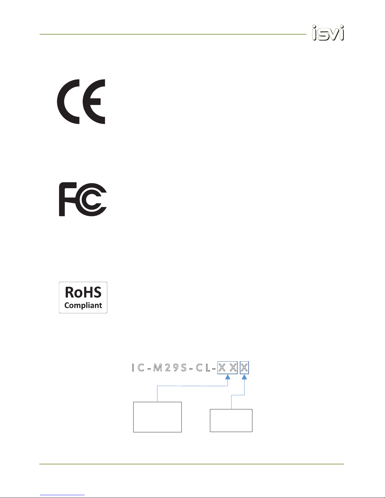
isvi IC-M29S-CL User manual

Operation Manual
IC-M29S-CL
High-Speed High-Resolution Camera Technology
Revision 1.0

IC-M29S-CL
2
High Speed - High Resolution Camera Technology
Revision History
Revision Date Description
1.0 20.07.2015 Initial Release
1.1 05.08.2015 Power Connector Drawings Correction

IC-M29S-CL
3
High-Speed High-Resolution Camera Technology
1. Introduction
Thank you and congratulations for purchasing the ISVI IC-M29S-CL (hereafter referred to as “camera”). We have
designed this camera to provide outstanding imaging performance and give you years of reliable service. As you
become familiar with the camera, you will appreciate the high quality of its production and the excellence in its
engineering design.
Please read and fully understand the entire manual before proceeding to operate your camera!
Intended Use Statement
This camera is a highly sophisticated electronic image capture device designed for use in industrial machine vision
systems.
The intended use and safe operation of the camera shall not be interfered with, even by unforeseen external
forces. Intended use and safe operation of the camera shall be carried out only by qualified technicians trained in
the installation and operation of electronic image capturing devices, accident prevention and common safeguards
for handling sensitive electronic devices. Operating the camera for any purpose other than the stated intended use
or by unqualified personnel may result in personal injury or property damage for which the manufacturer assumes
no liability.
Limitation of Liability and Indemnity Statement
This camera has been built to the high quality standards of ISVI Corp. and is delivered in full working order with
factory default settings. Please read and understand this manual and follow all safeguards and cautions for your
safety and to prevent damage to the camera. Please do not attempt to install this camera without adequate training
and knowledge of this specific camera. Any use or operation, modification or repair in contravention of this docu-
ment is at your own risk and will immediately void the user’s warranty. By acceptance of this camera you hereby
assume all liability consequent to your use or misuse of this camera.
To the maximum extent permitted by applicable law, ISVI Corp. shall not be liable for any damages suffered as a
result of using, modifying, contributing, copying, distributing, or downloading the materials, use of the camera
operation manual or use of any ISVI product and/or software. In no event shall ISVI be liable for any indirect,
extraordinary, exemplary, punitive, special, incidental, or consequential damages (including, without limitation, loss
of data, revenue, profits, use or other economic advantage) however arising, whether for breach or in tort, even if
ISVI has been previously advised of the possibility of such damage. You agree that you have sole responsibility for
adequate protection and backup of data and/or equipment used in connection with the product and software and
will not make a claim of any nature against ISVI for lost data, inaccurate output, work delays or lost profits resulting
from the use of any and all ISVI products and materials . You agree to indemnify, hold harmless and defend ISVI,
together with its affiliates, parent and subsidiary entities, successors, assigns, partners, managers, members,
employees, officers, directors and shareholders, from and against any and all damages, liens, liabilities, losses,
demands, actions, causes of action, claims, costs and expenses (including, without limitation, reasonable attor-
neys' fees, charges and disbursements, as well as the cost of in-house counsel and appeals) arising from or relat-
ed to ISVI, the use of this Operation Manual or any ISVI product and/or software.
Camera specifications, documentation, software applications and options are subject to change at any time
and at
the sole discretion of ISVI Corporation without notice.
1.1. Statement of Intended Use and Liability

IC-M29S-CL
4
High-Speed High-Resolution Camera Technology
Intended Use Statement
This camera is a highly sophisticated electronic image capture device designed for use in industrial machine vision
systems.
The intended use and safe operation of the camera shall not be interfered with, even by unforeseen external
forces. Intended use and safe operation of the camera shall be carried out only by qualified technicians trained in
the installation and operation of electronic image capturing devices, accident prevention and common safeguards
for handling sensitive electronic devices. Operating the camera for any purpose other than the stated intended use
or by unqualified personnel may result in personal injury or property damage for which the manufacturer assumes
no liability.
Limitation of Liability and Indemnity Statement
This camera has been built to the high quality standards of ISVI Corp. and is delivered in full working order with
factory default settings. Please read and understand this manual and follow all safeguards and cautions for your
safety and to prevent damage to the camera. Please do not attempt to install this camera without adequate training
and knowledge of this specific camera. Any use or operation, modification or repair in contravention of this docu-
ment is at your own risk and will immediately void the user’s warranty. By acceptance of this camera you hereby
assume all liability consequent to your use or misuse of this camera.
To the maximum extent permitted by applicable law, ISVI Corp. shall not be liable for any damages suffered as a
result of using, modifying, contributing, copying, distributing, or downloading the materials, use of the camera
operation manual or use of any ISVI product and/or software. In no event shall ISVI be liable for any indirect,
extraordinary, exemplary, punitive, special, incidental, or consequential damages (including, without limitation, loss
of data, revenue, profits, use or other economic advantage) however arising, whether for breach or in tort, even if
ISVI has been previously advised of the possibility of such damage. You agree that you have sole responsibility for
adequate protection and backup of data and/or equipment used in connection with the product and software and
will not make a claim of any nature against ISVI for lost data, inaccurate output, work delays or lost profits resulting
from the use of any and all ISVI products and materials . You agree to indemnify, hold harmless and defend ISVI,
together with its affiliates, parent and subsidiary entities, successors, assigns, partners, managers, members,
employees, officers, directors and shareholders, from and against any and all damages, liens, liabilities, losses,
demands, actions, causes of action, claims, costs and expenses (including, without limitation, reasonable attor-
neys' fees, charges and disbursements, as well as the cost of in-house counsel and appeals) arising from or relat-
ed to ISVI, the use of this Operation Manual or any ISVI product and/or software.
Camera specifications, documentation, software applications and options are subject to change at any time
and at
the sole discretion of ISVI Corporation without notice.
The following precautions must be heeded to avoid personal injury and damage to the camera
and/or supporting equipment.
Failure to comply with any of the following precautions will void the user’s warranty.
DO NOT attempt to disassemble, modify or repair the camera. Please contact your local ISVI Global Sales Partner if
you require repair or modification.
DO NOT short circuit any output or input signals.
DO NOT allow high-voltage or electrostatic discharge to come into contact with the camera. The camera should be
unpacked and handled in a clean, ESD protected workspace.
DO NOT operate the camera with any other voltage than is specified in this operation manual.
DO NOT expose the camera to electromagnetic fields. Image quality will degrade and, if strong enough, damage to
the camera may occur.
DO NOT allow direct laser beams, direct sunlight or other high-intensity light to project directly onto the imaging
sensor.
DO NOT expose the camera to temperatures and humidity levels outside of those specified in this operations manual.
DO NOT install the camera in a tightly enclosed space without ensuring proper heat dissipation and adequate venti-
lation.
DO NOT allow condensation to form on or in the camera and DO NOT allow the camera to come into contact with
any liquids, cleaning agents or solvents. Should the camera require cleaning, then only with a clean, lint-free cloth.
DO NOT expose the camera to shock and vibration levels outside of those specified in this operations manual.
DO NOT allow foreign objects or particles to enter the camera. Immediately install the camera lens mount cover
when lens is not mounted. When installing lenses, ensure that they are clean and they are not cross-threaded, tilted
or otherwise damaged. Contamination of the optical path/sensor may occur and/or removal of the lens may become
impossible. Installation of a lens should take place in a clean environment to avoid airborne contamination of the
optical path.
DO NOT attempt to clean the camera’s optical path yourself. Any damage to the optical path occurring from the
user’s attempt at cleaning it will void the warranty. If the optical path becomes contaminated, then please contact
your local ISVI Global Sales Partner for assistance.
DO NOT apply unnecessary pressure or stress on the camera’s cable connectors or pull or damage the camera
cables.
DO NOT use mounting screws longer or with different thread pitch than specified in the operation manual.
1.2. Precautions

IC-M2S-CL
5
High-Speed High-Resolution Camera Technology
CE marking and certification
(as per EN 50022-Class A Device)
The CE mark is a declaration by a manufacturer that European Union directives and
regulations controlling a specific product have been certifiably met.
This camera fulfills the requirements of current EU regulations relating to EN
50022. A corresponding declaration of conformity and documentation are available
upon request.
1.3. Standards Conformity
Federal Communications Commission (FCC / USA and Canada)
This equipment has been tested and found to comply with the limits for a Class A
digital device, pursuant to part 15 of the FCC Rules. These limits are designed to
provide reasonable protection against harmful interference when the equipment is
operated in a commercial environment. This equipment generates, uses, and can
radiate radio frequency energy and, if not installed and used in accordance with the
Operation Manual, may cause harmful interference to radio communications. Oper-
ation of this equipment in a residential area is likely to cause harmful interference
in which case the user will be required to correct the interference at his own
expense. Camera complies with FCC Form 47 Rules.
Changes or modifications to this unit not expressly approved by the part responsi-
ble for FCC compliance could void the user’s authority to operate the equipment.
Restriction of Hazardous Substances (RoHS).
The EU Directive 2002/95/EC Restriction of Hazardous Substances (RoHS) has
been in effect since July 1, 2006 and has been revised in 2011. The changes to
Directive 2011/65/EU, also known as “RoHS II” will slowly take effect over 6 years.
This directive restricts the use of six hazardous materials in EEE products. This
camera meets the current requirement for RoHS compliancy.
1.4. Ordering Information
I C - M 2 9 S - C L - X X X
Lens Mount**
FM = F-Mount
58 = M58x0.75
72 = M72x0.75
B=
BBAR*
I= IR-Cut
Filter**
* Monochrome standard with BBAR filter
LM = Leica - M
* Custom OEM available
*
N= None

IC-M29S-CL
6
High-Speed High-Resolution Camera Technology
Contents
1. Introduction ....................................................................... 3
1.1. Statement of Intended Use and Liability ........................................................ 3
1.2. Precautions .................................................................................................. 4
1.3. Conformity .................................................................................................... 5
1.4. Ordering Information ...................................................................................... 5
2. Overview ........................................................................... 9
2.1. Main Features ............................................................................................... 9
2.2. Specifications .............................................................................................. 10
2.3. Sensor spectral sensitivity .......................................................................... 10
2.4. Mechanical dimensions ............................................................................... 11
3. Installation ....................................................................... 14
3.1. Mounting the camera ................................................................................... 14
3.2. Thermal management .................................................................................. 14
3.3. Mounting a lens ........................................................................................... 14
3.4. Camera connections ................................................................................... 15
3.5. Trigger input schematic ............................................................................... 17
4. Image Acquisition ........................................................... 18
4.1. General ....................................................................................................... 18
4.2. Freerun mode............................................................................................... 19
4.3. Trigger Master mode .................................................................................... 20
4.4. Trigger Master Overlap mode ....................................................................... 21
4.5. Trigger Slave mode ...................................................................................... 22
4.6. Trigger Slave Overlap mode ......................................................................... 23
5. Camera Control and Features Description ..................... 24
5.1. Camera Control Tool Installation ............................................................... 24
5.2. User Workpace ........................................................................................... 25
5.3. Data Bits ..................................................................................................... 26
5.4. Image Processing ........................................................................................ 26
5.5. Test Pattern ................................................................................................. 26
5.6. Readout Mode ............................................................................................ 26
5.7. Version Information ..................................................................................... 29
5.8. Communication Window ............................................................................. 29
5.9. Temperature Sensor .................................................................................... 29
5.10. Trigger Mode ............................................................................................ 29
5.11. Trigger Source and Polarity ........................................................................ 29
5.12. Exposure Time .......................................................................................... 30
5.13. Strobe-out Polarity .................................................................................... 30
5.14. Gain .......................................................................................................... 31
5.15. Log Files ................................................................................................... 32
5.15. Gamma LUT .............................................................................................. 33
5.16. FFC / DPC ................................................................................................. 34

IC-M29S-CL
7
High-Speed High-Resolution Camera Technology
6. Command codes ............................................................ 36
6.1. Communication Specification....................................................................... 36
6.2. Communication Settings ............................................................................. 36
6.3. Command code Structure .......................................................................... 36
6.4 Command code list ..................................................................................... 36
- Readout ................................................................................................... 36
- ROI horizontal area .................................................................................... 37
- ROI vertical area ........................................................................................ 37
- Binning mode ............................................................................................ 37
- Data bits ................................................................................................... 37
- Test pattern ............................................................................................... 37
- LUT mode ................................................................................................. 38
- Reset ........................................................................................................ 38
- Defective pixel correction ........................................................................... 38
- Flat field correction .................................................................................... 38
- Flat field offset ........................................................................................... 38
- Generate flat field data ............................................................................... 39
- Save flat field data ..................................................................................... 39
5.1. Camera Control Tool Installation ............................................................... 24
5.2. User Workpace ........................................................................................... 25
5.3. Data Bits ..................................................................................................... 26
5.4. Image Processing ........................................................................................ 26
5.5. Test Pattern ................................................................................................. 26
5.6. Readout Mode ............................................................................................ 26
5.7. Version Information ..................................................................................... 29
5.8. Communication Window ............................................................................. 29
5.9. Temperature Sensor .................................................................................... 29
5.10. Trigger Mode ............................................................................................ 29
5.11. Trigger Source and Polarity ........................................................................ 29
5.12. Exposure Time .......................................................................................... 30
5.13. Strobe-out Polarity .................................................................................... 30
5.14. Gain .......................................................................................................... 31
5.15. Log Files ................................................................................................... 32
5.15. Gamma LUT .............................................................................................. 33
5.16. FFC / DPC ................................................................................................. 34

IC-M29S-CL
8
High-Speed High-Resolution Camera Technology
- Trigger mode ............................................................................................. 39
- Overlap mode ........................................................................................... 39
- Trigger source ........................................................................................... 39
- Trigger polarity .......................................................................................... 40
- Exposure time ........................................................................................... 40
- Strobe out offset ....................................................................................... 40
- Strobe out polarity ..................................................................................... 40
- VGA Gain .................................................................................................. 40
- VGA Gain offset ......................................................................................... 41
- Optical black clamp level ........................................................................... 41
- Optical black clamp level offset .................................................................. 41
- Config Initialization .................................................................................... 41
- Load & save config .................................................................................... 42
- Current Temperature ................................................................................. 42
- MCU Version ............................................................................................. 42
- Model Number .......................................................................................... 42
- FPGA Version ............................................................................................ 42

IC-M29S-CL
9
High-Speed High-Resolution Camera Technology
2. Overview
2.1. Main features
ROI (Region Of Interest) - freely programmable
FFC (Flat Field Correction)
DPC (Defective Pixel Correction)
2x2 & 4x4 Binning
Gain control - overall and individual taps
Black clamp level control
Gamma, programmable and download/upload LUT
Acquisition modes: Freerun / Trigger Master / Trigger Slave
Image data output & speed selectable
Exposure time control
Test pattern
External trigger input / External strobe output
Temperature monitoring
User settings saving areas
The ISVI IC-M29S-CL is a monochrome area scan camera utilizing the ON Semiconductor (previously Truesense
Imaging) KAI-29050, a high-sensitivity, high-dynamic range 29-megapixel CCD sensor. The IC-M29S-CL has an
8/10/12-bit, 2-tap, base configuration Camera Link digital interface and a rugged, compact form factor. Its flexible
acquisition modes include Free-Run, Trigger Master,Trigger Slave and Trigger Overlap. It also has a rich feature set
making the camera adaptable to any application environment.
The IC-M29S-CL combines the best possible CCD image quality with a very high resolution and extremely simple
connectivity to provide its user with the highest possible performance for the most demanding applications.
The IC-M29S-CL is suitable for a wide range of application areas including Factory Automation, Metrology,
large-scale 3D imaging, AOI, Flat Panel Inspection, LED Inspection, Print Inspection, Intelligent Transportation
Systems, Aerial Mapping, Aeronautics, Defense and more.

0.00
0.05
0.10
0.15
0.20
0.25
0.30
0.35
0.40
0.45
0.50
350400450500550600650700750800850900950100010501100
Absolute Quantum Efciency
Wavelngth (nm)
Measured with AR
coated cover glass
IC-M29S-CL
10
High-Speed High-Resolution Camera Technology
2.2. Specification
2.3. Sensor spectral response (Quantum efficiency)
Resolution
Pixel Area Size
Active Area Size
Output Format
Dynamic Range
CL Interface
Full Well Capacity
SNR
Acquisition Control
Exposure Control
Analog Control
Digital Control
Special Functions
Image Control
Lens Mounts
Operating Temperature
Relative Humidity
Shock / Vibration
MTBF
Power Requirements
Dimensions
Weight
Compliancy
Sensor
Storage Temperature
Sensitivity
Frame Rate
2 Tap Base Configuration, Single Cable
8/10/12-bit Monochrome
User Programmable H&V Region of Interest (ROI)
Binning 2x2 and 4x4
F-Mount, M72, M58, LM(Leica M), Custom OEM
-10℃to +70℃
20% - 90% non-condensing
25G (Half sine 6-10ms XYZ) / 10G (5-150Hz, 1min, XYZ)
> 78,500 h
12VDC ± 10%, 14.4W, ≤50mV Ripple
75mm x 75mm x 43.4mm without lens mount and connectors
460g (without lens mount), 600g (included F-Mount)
Camera Link v2.0, RoHS, CE, FCC
High-Sensitivity, Low-Noise CCD, Onsemi KAI-29050
6576(H) x 4384(V) Active Pixels
5.5µm(H) x 5.5µm(V)
Diameter : 43.7mm, 36.17mm(H) x 24.11mm(V)
, 35mm Optical Format
64dB
> 55dB
20000 e-
Free Run - Trigger Master - Trigger Slave - Overlap Mode
Programmable from 100 µsec to 7 sec in 100 µsec steps
Gain & Black Offset Level 0 - 700, 0.035dB Steps
Gamma, Programmable and Download / Upload LUT
Flat Field Correction, Defect Pixel Correction
User Flat Field Correction (FFC) calibration saving
User Defect Pixel Correction (DPC) calibration saving
0℃to +40℃, ext. temp.possible with reduced performance
34 uV/e-
4.45Hz Full Frame (224.7 msec)

IC-M29S-CL
11
High-Speed High-Resolution Camera Technology
2.4. Mechanical dimension
Figure 2.3 Outline drawings (F Mount)
F Mount
Mounting Hole
Screw specification

IC-M29S-CL
12
High-Speed High-Resolution Camera Technology
Figure 2.4 Outline drawings (M58 Mount)
M58 Mount
Figure 2.5 Outline drawings (M72 Mount)
M72 Mount

IC-M29S-CL
13
High-Speed High-Resolution Camera Technology
Figure 2.6 Outline drawings (LM Mount)
LM (Leica M) Mount

IC-M29S-CL
14
High-Speed High-Resolution Camera Technology
3. Installation
In this section you will find information on the proper means of mounting your camera in your system, connecting
the camera to a frame grabber and power supply, as well as ensuring proper electrical connections to the camera’s
I/O signals.
3.1. Mounting the camera
The camera has 8 mounting holes, 2 each top, bottom and sides. See the highlighted mounting hole specification
in Fig. 2.3 for their location and specifications.
Ensure that the maximum internal thread depth indicated in Fig 2.3 is not exceeded. The maximum torque which
can be applied to the mounting screws is 1.7Nm.
Using screws which are too long or are over-tightened may damage the camera!
3.2. Thermal management
Mounting the camera properly and adequately is required to ensure proper thermal management, which ensures
the best possible image quality. Thermal management means conducting heat away from the sensor in order to
keep it as cool as possible. Heat is one of the primary causes of dark current noise on the sensor which increases
photo response non-uniformity, dark signal non-uniformity, fixed-pattern noise and other image degrading effects.
The optimal conduction of heat from the sensor to the front and side surfaces is ensured by the design of this
camera. In addition to its internal thermal management design, this camera comes with an active cooling fan to
help maintain a constant operating temperature at any given ambient temperature. However, it is still necessary to
transfer heat away from the camera surfaces by mounting the camera to a solid metal surface of adequate mass
using the mounting holes found on the camera. The attachment of heat sinks to the camera sides can also aid in
the transference of heat.
This camera is designed to operate at an ambient temperature between 0°C and +40°C. Operating the camera
between 40°C and maximum 70°C will result in reduced image performance and camera lifetime. Do not operate
the camera at temperatures above 70°C!
3.3. Mounting a Lens
This camera is equipped with a lens mount designed for use with high-precision industrial lenses. All lens mounts
available for this camera are engineered with specific dimensions and very tight tolerances.
When mounting a lens to the camera, ensure that the lens is held parallel with the lens mount and never forcibly
assert pressure to attach the lens. Ensure that the lens is not cross-threaded to the mount. Damage to the camera,
lens mount and lens may occur!
When mounting an F-mount lens, ensure that the lens is inserted properly before turning counter-clockwise until
the locking tab clicks into place.
When removing an F-mount lens, push the locking tab towards the camera body and turn the lens clockwise.

IC-M29S-CL
15
High-Speed High-Resolution Camera Technology
3.4. Camera connections
The camera connections are laid out on the back panel of the camera as follows:
1
13
14
26
Power input connection
(Hirose 6-pin)
Camera link connection
(MDR-26)
Control I/O connection
(Hirose 12-pin)
3.4.1 Camera Link0 connection
The Camera Link0 connection adheres to the latest Camera Link Standard. It is used for data, communication and
I/O signal transfer to/from a Base Configuration Camera Link frame grabber. It has a 2tap (8/10/12-bit) configura-
tion.
Figure 3.1 Camera connectors
Pin No I/O Signal Name Pin No I/O Signal Name
1 Ground Inner shield 14 Ground Inner shield
2 OUT X0- 15 OUT X0+
3 OUT X1- 16 OUT X1+
4 OUT X2- 17 OUT X2+
5 OUT XCLKOUT- 18 OUT XCLKOUT+
6 OUT X3- 19 OUT X3+
7 INPUT RX+_SERTC+ 20 INPUT RX-_SERTC-
8 OUT TX-_SERTFG- 21 OUT TX+_SERTFG+
9 INPUT CC1-(Trigger-) 22 INPUT CC1+(Trigger+)
10 INPUT CC2+ 23 INPUT CC2-
11 INPUT CC3- 24 INPUT CC3+
12 INPUT CC4+ 25 INPUT CC4-
13 Ground Inner shield 26 Ground Inner shield
Figure 3.2 Camera Link0 Pin Assignments
R
Cam Link0
Power
Control

IC-M29S-CL
16
High-Speed High-Resolution Camera Technology
3.4.2 Power input connection
The camera power input connector is a Hirose 6 pin connector (part # HR10A-7R-6P) and is used exclusively to
power the camera. Pin layout and configuration are shown in Figure 3.3.
Pin Number Signal
1, 2, 3
4, 5, 6
VCC, +12VDC
GND, Ground
Power Connector
Mating connector: Hirose HR10(A)-7P-6S
Figure 3.3 Power input connector
It is recommended to use a direct current (DC) regulated power supply rated to at least 1.2 Amps current with
output voltage of 12VDC ±10%. The camera employs a self-recovery fuse for protecting against reverse voltage
and overvoltage. However, applying reverse voltage or overvoltage may damage the camera and void the warranty.
3.4.3 Control I/O connection
The Control I/O Connection is used for supplying the camera with an external TTL trigger input as an alternative to
the CC1 Trigger Input on the Camera Link connection. It is also used for supplying an external strobe output trigger
which is synchronized with the start of exposure.
Pin Number Signal
1
2
+ Trigger Input
- Trigger Input
Control Connector
Mating connector: Hirose HR10(A)-10P-12P
Figure 3.4: Power input connector
3
5
4, 6-12
Strobe Output
GND, Ground
Reserved - Do not connect
The reserved pins are used by the ISVI Camera Firmware Upgrade Cable for field firmware upgrading. Do not
connect these pins – damage to the camera may occur! See seperate manual provided for more detailed informa-
tion about firmware upgrading.
Do not apply voltage to the Strobe Output or GND pins. Damage to the camera may occur!

IC-M29S-CL
17
High-Speed High-Resolution Camera Technology
3.5 Trigger input circuit
Figure 3.5 shows the trigger signal input circuit of the 12-pin Control I/O connection. The trigger signal entered is
delivered to the internal circuit through a photo coupler.
Trigger pulse width must be a minimum of 100µsec. If the trigger pulse width supplied to the camera is less than
100us, trigger signal will be ignored by the camera and an image will not be taken.
1
TRIGGER (+)
TRIGGER (-)
0V
3.3V ~ 5V CAMERA
[HR10A-10R-12SB]
STROBE OUTPUT
Opto Coupler
12Pin Connector
Hirose : HR10A-10R-12SB
2
3
4
Figure 3.5: Trigger Input Circuit
3.6 Strobe output circuit
The strobe output signal is output through a TTL Driver IC with a 3.3 V output level. The start and the pulse width
of the output signal is in synchronization with the exposure timing of the camera.
Do not apply any voltage to the Strobe Output pins – damage to the camera will occur and the warranty will be
voided!
Figure 3.6: Trigger Output Schemetic
User Recommand Application ISVI Camera
3
5
0V
3.3V
User Recommand Application

IC-M29S-CL
18
High-Speed High-Resolution Camera Technology
4. Image Acquisition
The camera has 5 acquisition modes which can be selected for a high degree of flexibility in any application
environment.
• Free-Run
• Trigger Master
• Trigger Master Overlap
• Trigger Slave
• Trigger Slave Overlap
Each acquisition mode is selectable using the ISVI Camera Control Tool for this camera.
A red LED status light is on the back panel of the camera (see Figure 4.1) and indicates through its on/off timing
which acquisition mode the camera is currently in.
4.1. Overview
Freerun
Trigger Master
Trigger Slave
Trigger Master
(Overlap)
Trigger Slave
(Overlap)
0.50 second
0.25 second
Figure 4.1: Acquisition Mode LED Status (Solid shaded areas indicate LED = ON)
Acuisition Mode LED Status
The exact timing of Trigger Acquisition Modes is dependent on parameters both internal and external to the
camera. Section 4 describes the dependencies of the internal parameters in relation to the external ones.
Frame Read Out period = 224.7msec

IC-M29S-CL
19
High-Speed High-Resolution Camera Technology
4.2. Free-run Mode
In Free-Run mode the camera creates its own internal trigger and continuously acquires images without the need
for any external triggers. The exposure time is selectable by the user and it determines the cycle time of the inter-
nally generated trigger. The Free-Run mode is always running in Overlap mode (exposure during previous frame
readout). Therefore, the maximum frame rate for a given exposure time can be achieved in this mode.
Programmed
Exposure Time
N-1
Programmed
Exposure Time
N
Programmed
Exposure Time
N+1
Exposure
Transfer Time Transfer Time Transfer Time
Readout Time Readout Time Readout Time
FVAL
Readout Image N-1 Image N Image N+1
Figure 4.2: Free-run Mode

IC-M29S-CL
20
High-Speed High-Resolution Camera Technology
Trigger
Readout Time Readout Time
Exposure
Readout Image N Image N+1
Programmed
Exposure Time
N
Programmed
Exposure Time
N+1
Ignored
Trigger
Figure 4.3: Trigger Master Mode
4.3. Trigger Master Mode
In Trigger Master mode the camera controls the Exposure period (Master condition) which is programmed in the
camera by the user. The camera then waits for an external trigger to be applied to CC1 of the Camera Link connec-
tion or to the External Trigger pin of the I/O connection. Once a trigger is detected by the camera, then the
programmed Exposure begins.
Readout of the image occurs after the end of the Exposure period.
If a new trigger is sent to the camera during the previous readout period, then it will be ignored. If a new trigger is
sent to the camera during the previous exposure period, then the timing will be reset and the previous image will
not be readout. Once programmed exposure and readout are completed the camera waits for the next valid trigger.
Table of contents