Italkero Poster PE t1 70 User manual


2GENERAL
COMPLIANCE
Our appliances are compliance at:
Gas directive 2009/142/CE (ex. 90/396/CEE)
Electromagnetic directive compatible 2004/108/CE
Low-tension directive 2006/95/CE 0694
RANGE
30
(senza TIMER)
MODELLO CODICE
PE30T1 M0100
50
(senza TIMER)
PE50T1 M0100
70
(senza TIMER)
PE70T1 M0100
90
(senza TIMER)
PE90T1 M0100

Kind Technical
We thank you for choosing the convector. We can assure you its performance will be long lasting,
reliable when it is installed and used properly (manufacturerʼs guidelines are followed).
Good work and thanks
The Manufacturer.
3
GENERAL
WARRANTY
Provided that it is fitted in accordance with the Manufacturer's instructions, this appliance
benefits from the statutory warranty.

GENERAL
General informations pag.5
Safety rules pag.5
Convector description pag.6
Identification pag.6
Structure pag.7
Technical data pag.8
Accessories pag.8
Electrical scheme pag.9
Control panel pag.10
INSTALLATION
Receiving the product pag.11
Weight and dimension pag.13
Installation
- Apparatus choice location pag.14
- Intake & exhaust tube fumes assemblage pag.15
-- Tube Kit Ø 32 o Ø 54 mm with unique term. (Standard) pag.17
-- Tube Kit Ø 32 o Ø 54 mm with single term. (Speciale) pag.18
- Convector assemblage pag.23
Electrical collegaments pag.24
Gas connection pag.24
CUSTOMER SERVICE
Preliminary operations pag.25
First service start pag.25
Processor control box malfunction pag.26
Controls during the first & after starting service pag.26
Gas transformation pag.27
Regolation pag.28
Ordinary maintenance pag.29
Convector clean out pag.29
Components replacement pag.30
Disassembly & reassembly of the skirt pag.34
Eventual anomalies & remedies pag.34
Useful information pag.36
This Manual is composed by 30 pages.
4GENERAL
In same parts of the book there are used these symbols:
Attention: it used to underline particular caution or actions.
Prohibited: it used to underline the actions that don’t half to
be executed.
INDEX

We like to remember that, products that use combustion
or electrical energy there is security rule to observe
before operating.
Do not allow children to be near the convector.
It is prohibited to turn on an electrical device if there
is a gas smell.
In this case:
- Open windows and door.
- Close the gas tap.
- Call a Technical Service Assistance.
It is prohibited to touch the convector with wet hand
or other parts of your body.
-Electrical Hazard: Do not touch the convector with
wet feet or other part of your body.
It is prohibited to clean the convector when it is run-
ning.
It is prohibited to pull, remove and wring electric
wires outside the convector also if the electrical
supply is turned off.
It is prohibited place over the convector, towels, tea
clothes and other could be cause of inefficiency or
also source of hazard.
It is prohibited to leave paper, plastic, or other things
of the convector box outside within a childʼs reach.
It is prohibited to disperse and leave packaging com-
ponents for the children handy.
It could be potential source of hazard.
Check if there is everything in the packing. In case of
messing pieces call the Agent that sold you the
apparatus.
The convector installation has to be done by a quali-
fied person or by a qualified enterprise that has
received a qualification. The enterprise has to relea-
se you the installation conformity statement tells you
the work is correctly done, and follows the safety
rules laws, “of the 5 March1990 n 46”.
The convector has to do the work that it has been
projected for; if this is not respected there is no war-
ranty.
If the convector is going to be shut down for a long
period of time, the following steps should be taken:
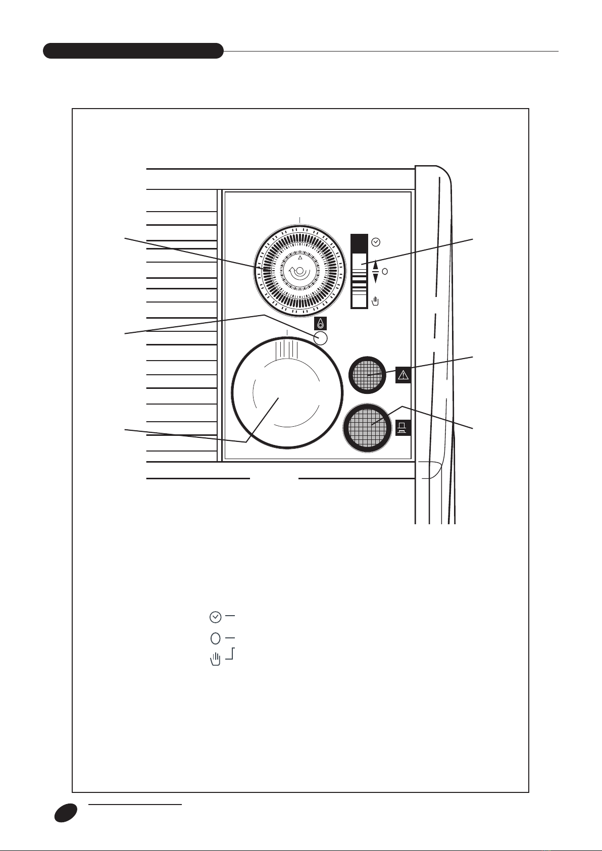
-Position the main switch that is on the control panel
to the “off” position.
-Position the general or wall switch to the “off” posi-
tion and unplug the electrical cord.
Close the gas tap.
This book is a part of the convector, please read and
save all instructions for future reference.
5
GENERAL
GENERAL INFORMATIONS
SAFETY RULES

The convector is identified through:
- Packed label:
A label that indicates the code and the combustion it
uses to identifies the convector.
- Technical label:
The technical label reports the matrices numbers,
the gas prearrangement, and technical observation.
-Gas prearrangement label:
It reports the kind of gas the convector has to use,
and if there is a transformation from one kind of gas
to another you have to change the old label.
Spare parts, or technical operation require, a
precise identification of the type of model.
If there is going to be any tampering of the technical
label, this will not consent the right identification of
the apparatus.
The convector is a gas radiator that heat up the
atmosphere.
It has an intake of air that goes in the combustion
chamber type C.
The convector is made with an aluminium body that
allows a high efficiency of heat; it also has a fan that
allows the dispersal of air faster in the rooms.
The convectors are arranged in factory for the func-
tion at gas methane and they can be transformed to
GPL(G30/G31) using the furnished nozzle kit.
Note: At request the apparatus can be furnished
already arranged at GPL.
It also has an electrical device that allows you to do
a series of things.
There also is a Processor Control Box (P.C.B
assy) that controls all the principalsʼfunction of
the apparatus.
After there is the Control Panel that has other
options.
6GENERAL
Natural Gas
LPG
CONVECTOR DESCRIPTION
IDENTIFICATION

7
GENERAL
1 Water tank (optional)
2 Room Thermostat
3 Timer (optional)
4 Reset
5 Main switch
6 Heat exchanger
7 Ignition and detection electrode
8 Diode Bridge
9 Gas valve
10 Atmosphere thermostatic Feeler
11 Line Connector + EMC filter
12 Centrifugal Fan
13 Tangential Fan
14 Fuse protection
15 Processor control box
16 Technical labels
17 Heat exchanger
18 Safety thermostat
13
15
16
17
14
1112
4
5
6
8
7
9
10
321
18
STRUCTURE

The following options are available upon request:
8GENERAL
Terminal capacity nomination (qn)
Right efficiency
Nozzle pressure
Gas consumption (15∞C)
Type of apparatus
Combustion category
Efficiency class
Nozzle
Max/min value Atmospheric heated by a convector
Quantity of air heated
Electrical alimentation
Power absorbed when in function
Protection degree
MODEL
kW
kW
%
mbar
m3/h
kg/h
n∞
Ø
m3
m3/h
V~Hz
W
Terminal capacity nomination (Pn) kW
kW
30
Methaan
G30/G31
3,2
91
12
0,34
C13 - C33 - C53 - C63
II2H3+
1
3
230~50
100
IP20
28,8/36,7
0,25/0,24
0,92 0,52
78/46 78/46
130 130
50
Methaan
G30/G31
5,5
91
12
0,58
28,5/36,6
0,43/0,42
1,20 0,68
166/78,8 166/78,8
225 225
70
Methaan
G30/G31
8
91,8
12
0,85
28,5/36,5
0,63/0,62
1,42 0,82
197/115 197/115
335 335
80
2,91 5 7,35
90
Methaan
G30/G31
10
91
10
1,06
27,4/34,5
0,79/0,77
1,65 0,95
246/143 246/143
419 419
9,10
Nominal inlet pressure mbar
20
29/37
20
29/37
20
29/37
20
29/37
DESCRIPTIONS Code
7000000666
7000000676
7000000700
7000000720
7000000710
7000000350
7000000600
7000000730
7000000370
7000000390
7000000380
7000000755
7000000350
7000000365
7000000740
7000000280
7000000686
7000000696
7000000270
7000000850
7000000840
7000000465
7000000466
7000000375
7000000705
7000000365
7000000610
Distance wall support for the 25
Distance wall support for the 45
Curves of 90∞Ø 32mm tube/connection
Extension Ø 32mm L = 500mm
Extension Ø 32mm L = 1000mm
"GP" Out side grill protection for Single Term. Ø 32mm
"GPu" Out side grill protection for Unique Term. Ø 32mm
Chimneypot Ø 32mm
Curves 90∞Ø 54mm tube/connection
Extension Ø 54mm L = 500mm
Extension Ø 54mm L = 1000mm
Curve 90∞Ø 54mm dye-cast
"GP" Out side grill protection for Single Term. Ø 54mm
"SDP" Embedding screen for Single Term. Ø 54mm
Chimneypot Ø 54mm
Week TIMER
Distance wall support for the 65
Distance wall support for the 85
Day TIMER
Tube insulator Ø 54mm L = 1000mm (conf. 4 pz.)
Tube insulator Ø 32mm L = 1000mm (conf. 5 pz.)
Intake/exhaust terminal Ø 54mm L = 6 cm
Intake/exhaust terminal Ø 32mm L = 5 cm
Curve 135∞Ø 54mm
Curve 135∞Ø 32mm
"SDP" Embedding screen for Single Term. Ø 32mm
"GPu" Out side grill protection for Unique Term. Ø 54mm
TECHNICAL DATA
ACCESSORIES

9
GENERAL
BL blue cable
CF processor control box (P.C.B assy)
CVT condenser
EA starting electrode
ER revelation electrode
EV gas valve
Ffuses
FACL filter
IG General switch
Lphase line
Nneutral line
Owatch programmer
PD-EV valve gas &Diode Bridge
PD-HL Diode Bridge modulate
PR reset switch
PS differential pressure switch
RD red cable
SP Power selector
TA atmospheric thermostat
TL limit thermostat
TV ventilation thermostat
VC combustion fan
VT tangential fan
WH white cable
EV1 EV2
PE-Timer
Electrical Scheme
1513
TL
8 9 10 11 12
VC
C
1
2
1
3
2
TA
TIMER
LN
1 2 3 4 5 6 7
34
21
5
4
II I O
V. T.
30 - 50
30-50
70-90
PS
IG L1
14
PR
L3
CVT
FACL
70 - 90
V. T.
BL
RD
WH
EV
PD
ER
EA
19 18 17 16
4AF
21 20
M5 M3
EV1 EV2
PE
Electrical Scheme
1513
TL
8 9 10 11 12
VC
C
1
2
TA
LN
1 2 3 4 5 6 7
34
21
II I O
V. T.
30 - 50
30-50
70-90
PS
IG L1
14
PR
L3
CVT
FACL
70 - 90
V. T.
BL
RD
WH
ER
EA
19 18 17 16
4AF
21 20
M5 M3
CF CF
Nordgas
Brahma
EV
PD
Nordgas
Brahma
ELECTRICAL SCHEME

1
2
3
4
5
6
7
16
17
18
19
20
21
22
23
24
1
2
3
4
5
6
7
8
9
10
11
12
13
14
15
16
17
18
19
20
21
22
23
24
1
2
3
4
5
6
7
8
9
10
11
12
13
14
15
1
2
3
4
5
6
1Timer
2Function signal
3pheric thermostat
4Function selectors
Timer programming fan function
Radiator deactivation
Radiator function, this button works at seconds
the atmospheric temperature thermostat.
5Unblocking or (trigger) button.
6Main Switch
10 GENERAL
CONTROL PANEL

The convector is furnished in a box that contains:
- Convector
- Stirrup support
- Kit gas transformation
- Owner book information
- Technical service assistance and install tort book
- Spare parts book
- arranty certificate
- Label Code bar
%$"# #$"#$"
To install the radiator you need to have the right
tubes kit for the intake and exhaust fumes tubes to
realize. You need to order the tubes kit separately
from the apparatus.
Tube kit Ø 32 mm
The kit is compound of
Q.ty Description
1 position paper jig for the radiator
6 Inserts of Ø 8 mm (for fastening the template
to the wall)
1 Gas tap with pipefitting (connections)
1 Pipe fitting adapter for Ø 32 mm with faste
ning screw
6 Self threading screw for tube fastening
2 Tube Ø 32 mm L = 500 mm
1 Integrated unique terminal
4 Inserts Ø 6 mm
1 Antivibrating
For the installation see following pages.
11
INSTALLATION
RECEIVING THE PRODUCT

12 INSTALLATION
Tube kit Ø 54 mm
The kit is compound of
Q.ty Description
1 position paper jig for the radiator
6 Inserts of Ø 8 mm for fastening the template
to the wall
1 Gas tap with pipefitting
1 Pipe fitting adapter for Ø 32 mm with faste
ning screw
6 Self threading screw for tube fastening
2 Tube Ø 32 mm L = 500 mm
1 Integrated unique terminal
4 Inserts Ø 6 mm
1 Antivibrating
For the installation see following pages.
Tube kit Ø 32 mm
The kit is compound of
Q.ty Description
1 position paper jig for the radiator
6 Inserts of Ø 8 mm for fastening the template
to the wall
1 Gas tap with pipefitting
1 Pipe fitting adapter for Ø 32mm with faste
ning screw
3 Curves Ø 32mm
3 Tube Ø 32 mm L = 500 mm
2 Tube Ø 32 mm L = 1000 mm
2 Tube terminal Ø 32 mm
2 Stainless steel flange
8 Inserts Ø 6 mm
1 Antivibrating
For the installation see following pages.

Tube kit 0 54 mm
The kit is compound of
Q.ty Description
6 Inserts of Ø 8 mm for fastening the template
to the wall
1 Gas tap with pipefitting
1 Pipe fitting adapter for Ø 32 mm with faste
ning screw
2 pressurefusion curves
3 Tube Ø 54 mm L = 500 mm + o ring
2 Tube Ø 54 mm L = 1000 mm +o ring
2 Terminal tube Ø 54 mm + o ring
2 Plastic rosone
2 Turning vane
1 Curve M/F + O ring
1 Antivibrating
For the installation see following pages.
!&$#
hen the radiator is being installed be sure that all
the tubes are adjusted for the installation you want
done. The tube kits available are:
30
50
70
90
MODEL CODE
KIT std. EXHAUST & INTAKE Ø 32mm (1 INDIVIDUAL)
Description
KIT std. EXHAUST & INTAKE Ø 54mm (1 INDIVIDUAL)
KIT special EXHAUST & INTAKE Ø 32mm (2 SINGLES)
KIT special EXHAUST & INTAKE Ø 54mm (2 SINGLES)
KIT special EXHAUST & INTAKE Ø 32mm (1 INDIVIDUAL) INTERNAL Installation
KIT special EXHAUST & INTAKE Ø 54mm (1 INDIVIDUAL) INTERNAL Installation
TP320S 00000
TP540P 00000
TP32SP 00000
TP54SP 00000
TP3206A5 00
TP5410A5 00
13
INSTALLATION
Depth ( B )
mm
30
225
Height ( A )
mm
580
Width ( C )
mm
508
Weight
kg
21
DESCRIPTION
50
225
580
658
27,7
70
225
580
808
34
90
225
580
958
41,2
WEIGHT & DIMENSION
c
a
b

14 INSTALLATION
GENERAL INFORMATIONS
This apparatus is tin respect to the environment; the
air is intake from the outside.
-When the convector is being installed do not use
other pieces that are not give from the manufacturer.
-Donʼt let the electrical cable touch heated parts, like
the grill or the intake & exhaust tubes.
Is the installation duty to tell the owner the behaviour
to keep during the apparatus function.
- To avoid problems donʼt place cloth or other things
on top of the grill.
-Donʼt block with cloths or rug the apparatus intake &
exhaust tubes.
APPARATUS CHOICE LOCATION
Before youʼre going to install the convector, check if
there is enough space for the correct function of the
convector.
Check if around the convector tubes there are mate-
rials that can support the heath, second check if the
wall is made of the right material and can support the
convector weight.
Verified if around the exhaust fumes tubes, there is
no wood or plastic but there is the right material that
can support the heath.
The material where the convector it going to be pla-
ced has to resist the exhaust tube heath (about
180°C).
In case of low resistant wall material itʼs possi-
ble to realize a cavity around the exhaust fume
tube, and insulate with strong material for the pre-
sent temperature, otherwise execute a hole with a
larger diameter at least 4 cm respect to the exhaust
fume tube.
Its prohibited settles the convector in rooms like
bath, or showers. For this installation you need
to realize special protections that make the appara-
tus consistent to the Electrical security rules.
INSTALLATION
Min.
150
Min.
150
Min.
50

Installation stage
The convector installations stages are:
- Apparatus choice location
- Tube installation
- Parallel tube kit Ø 32 mm or Ø 54 mm with unique
terminal (standard)
- Separated pip kit Ø 32 mm o Ø 54 mm with single
terminal (special)
- Convector installation
- Electrical collegaments
- Gas connection
TYPE OF INSTALLATION SECOND UNI CIG 7129
As we go on we are going to show you the types of
installation second by the Uni Cig 7129 rule.
INTAKE AND EXHAUST TUBE FUMES ASSEM-
BLAGE
The intake & exhaust tubes can be embedded insi-
de the wall, or in sight, they have to be protected to
avoid, risk condition. To have the apparatus in sight
it exist a spacing bar so that you can see the tubes,
we recommend that the unloaded tubes have to
have a good insulation using materials that have
also a resistant of more 200° C° (ex. HT/-
Armaflex) of temperature. Realize the holes for
fastening the tubes, after establish the hangersʼ
length; insert it in the right position.
Before assembling the tubes kit verifying that the
Max tube length has been respected, even the
Max loaded loss provided (See table).
50 MIN
A B
RIGHT SIDE
L
h
C
D
b
a
in mm
A
Overall dimensions
50
450
70
600
90
750
B
204 204 204
C
312,5 312,5 312,5
D
267,5 267,5 267,5
h
580 580 580
L
658 808 958
30
300
204
312,5
267,5
580
508
15
INSTALLATION
¯ unloaded intake tubes
¯ Wall hole single terminal tubes
Max single terminal tube length
Min comprehensive tube length
Loaded loss tube L = 500mm
Loaded loss tube L = 1000mm
Loaded loss single terminal
Loaded max loss permissible ( )
30
80 80
Loaded loss tube curve 90¡ (die)
mm
mm
m
mm
Pa
Pa
Pa
Pa
Pa
54
110
15
0,5
0,7
4,4
2
20
54
110
15
0,6
1
9
4
20
32
65
1
6
11
-
9
50
32
65
5
3
5
-
5
50
80
54
110
15
0,8
1,6
0,3
4
30
50 70 90
80
54
110
10
1,2
2,25
4,3
6
25
30 50 70 90
MAX length tubes with separate terminal m15 15310 15 10
Loaded loss tube curve 90¡ Pa0,7 1,512,25,8 0,05 0,7

TEMPLATE AND STIRRUP ASSEMBLAGE
To position the template & stirrup use the paper
mask then marked, and execute hole B (Ø 8 mm).
-Fasten the stirrup with one of the 4 inserts Ø 8 mm
furnished
-Mark, and execute the other 3 holes (Ø 8 mm) in the
corresponding buttonholes present on the stirrup and
on the template, fasten with the 3 inserts.
-Mark on the wall the centre for a hole for the intake tube.
If you find difficult to mark the hard covering for the
adepter connection hole you need to perforate with
the bit Ø 6 mm to this use the template.
For normal plaster is enough to pass through the
fasten holes a bit Ø 3 mm.
- Then take off the outline from the template and then
you can start perforate the hole for the
--- Tube kit Ø 32 mm: only centre disk
--- Tube kit Ø 54 mm: centre disk + ring
- Execute a hole of Ø 65 mm in the wall (tubes Ø 32
mm) or a hole Ø 110 mm (tube Ø 54 mm).
IMPORTANT! For 70 and 90 versions, fit the addi-
tional template (1) in the area of the holes (2)
using the supplied screws.
Tubes group adapter connection
To realize the group is necessary adapter tube
lengths so that it will increases a space from the wall
of 25 mm.
The cut has to be perpendicular to the axes tube,
being carefully do not deform the tube, then cut them
at measure for the connection adepter.
To fasten the tubes assemblage, use silicone grease
and verified that the O-ring donʼt come out from there
seating.
In the case that the distance support itʼs going to be
used, the adapter connection will be fasten directly to
the support, and the tubes will feed in the buttonhole
provided on this.
Min.
150 mm
Min.
150 mm
Min.
150
Min.
150
b
a
16 INSTALLATION

Outside grill assemblage (cod 7000000350)
To assemble the grill you only need the inserts, and
the steeliness steel flange.
Assemblage SDP protection (cod 7000000365)
The assembling is execute in the following way:
-After you have drilled on the outside wall put the
protection with mortar
-Assemblage the terminal tube with the equipment
screws
-Adapt the terminal to the tube length and grill pro-
tection between the walls.
The tube cuts have to be perpendicular being real
careful do not deform.
Kit parallel tube Ø 32/54 mm with unique terminal
(standard)
This kind of system is used when the unloaded fume
and the intake of air are next to the apparatus.
Assemblage the adapter tubes connection uni-
que terminal, from the out side.
-Insert in the wall the assembled group adapter con-
nection, angles, and curves.
Position the unloaded/intake tubes at thread outside
wall, being real careful that the short tube is always
up (unloaded tube)
-Fasten the group adepter connection to the templa-
te with the screw set.
-Insert the unique terminal until the plastic ring tou-
ches the wall.
-Mark with a punch the holes for the fastening
-Cut the terminal then make the hole for the inserts
Ø 6 mm
-Fasten the unique terminal to the wall using the
inserts Ø 6mm seeing that the unloaded tube is
toward up.
Ascertain that the adapter tubes connections
are correctly inserted. To fasten the tubes
assemblage, use silicone grease and verified that
the O-ring donʼt come out from there seating.
Before you wall up the tubes, provide to insulate the
exhaust fume tube with material resistant to the 200°
C° (ex. HT/-Armaflex)
17
INSTALLATION
1
2
Ø32
Ø54
Ø32
Ø54
Ø32
Ø54
GP
SDP
GPu

How to mount special pipes kit from inside the
room to be warmed.
Drill the hole on the wall. Shorten the special
pipes in order to match the real thickness of the
wall (see picture).
IMPORTANT: Cutting must be perpendicular to
the pipe axis, please handle with care in order not
to deform the pipes.
Before you insert the pipes through the hole you
must fix the SPECIAL KIT to the fitting connector by
screws on issue.
Insert the whole assembling (Special kit + fitting con-
nector) through the hole on the wall. Fix it on the
metal mounting template by screws on issue.
Tube kit Ø 32 mm o Ø 54 mm with unique termi-
nal (SPECIAL).
This kit, uses separate tubes and are indicated when the
exhaust fumes and intake are fore way the apparatus.
The type of installation are more than one kind, but
they can be lead to the 3 example described in this
chapter.
Template and stirrup assemblage
To position the metal template & the convector stir-
rup support hold it horizontal to the paper mask then
marked hole Band C(Ø 8 mm).
After make Ahole for the exhaust fume tube.
If you find difficult to mark the hard covering for
the adepter connection hole, you need to perfo-
rate the two holes with the bit Ø 6 mm to this use the
template. For normal plaster is enough to get throu-
gh the fastening holes with the bit of 3 mm.
Before pipes kit assemblage, verifying maxi-
mum pipes length be respected, considering
the maximum pressure leak consented (see
below chart).
Ø unloaded intake tubes
Ø Wall hole common terminal tubes
Max common terminal tube length
Min comprehensive tube length
Loaded loss tube l= 500 mm
Loaded loss tube l =1000 mm
Loaded loss single terminal
Loaded max loss permissible (*)
3.0
80 80
Loaded loss tube curve 90∞diecast
mm
mm
m
mm
Pa
Pa
Pa
Pa
Pa
54
110
15
0,5
0,7
2
20
54
110
15
0,6
1
4
20
32
65
1
6
11
9
50
32
65
5
3
5
5
50
80
54
110
15
0,8
1,6
4
30
5.0 7.0 9.0
80
54
110
10
1,2
2,25
6
25
3.0 5.0 7.0 9.0
Max separate terminal tube length m15 15310 15 10
Loaded loss tube curve 90∞Pa
4,4 9-- 0,3 4,3
0,7 1,512,25,8 0,05 0,7
Min.
150
Min.
150
C
A
D
E
B
18 INSTALLATION

Chances A1/A2 tube assemblage in wall.
This solution can be adapted when the wall thick-
ness consent to execute the trace for the connection
tubes, and can be realize in two ways:
-Chance A1 (with tube Ø 32 & 54 mm)
For the unloaded & intake tube installation
-Mark the centre (A) execute the hole Dfor the (Ø 35
mm) for the tube Ø 32 mm otherwise (Ø 65 mm) for
the tube Ø 54 mm.
-Execute trace in the wall for the tube and curve
remaining.
-Fasten the template to Bhole with an inserts Ø 8 mm.
-Put the hanger (stirrup) on the template then hold
both on the Chole.
-Execute two holes Ø 8 mm correspondence at the
buttonhole then you can finish to fasten the appara-
tus with the inserts.
If you find difficult to mark the hard covering for
the adepter connection hole, you need to perfo-
rate the two holes with the bit Ø 6 mm to this use the
template. For normal plaster is enough to get throu-
gh the fastening holes with the bit of 3 mm.
Before you wall up the tubes, provide to
insulate the exhaust fume tubes, with strong
materials resistant at a greater temperature of
200 °C (ex. HT/-Armaflex).
Min.
150
Min.
150
C
A
D
E
B
19
INSTALLATION
A1
A2
MIN
200
mm

Group adapter connection tube
The group adapter preparation is effected by two
kinds of tubes Ø 32/54 mm
-- With Ø 32 mm tubes.
- Adapt the length tube; to the wall space so it
increases 25 mm, then cut it.
- Assemble the tube (1) cute at right measure, and
the curve (2) for the adapter connection (3) then
fasten with the furnished screws.
The unloaded tube has to be toward up and in corre-
spondence to the shortest outside tube of the adap-
ter connection.
- Assemble the unique terminal (4) on the tube (1)
fastening with the furnished screws in the way that
extremity tube appears at line of the terminal but-
tonhole.
- Take off the paper mask from the template, insert
the assembled group in the wall positioning in the
way that the tube extremity is at line to the outside
wall, then fasten the connection adaptor to the tem-
plate with the furnished screws.
-- With Ø 54 mm tubes
- Adapting the length tube; to the wall space so it
increases 25 mm, then cut it.
- Open the group adepter connections disassemble
the two flanges (1) unscrew the screws (2) take off
the reductions (3 only for the 0 32mm tubes) then
assemble the group.
- Assemble the unique terminal (4) to tube (5).
The cut has to be perpendicular to the axe
tubes, being real careful donʼt deform.
At the cut, take away real carefully the featheredge,
after make the fastening holes.
+25mm
L
L
3
2
1
4
1
5
2
4
1
5
2
4
3
6
20 INSTALLATION
This manual suits for next models
3
Table of contents
Other Italkero Heater manuals
Popular Heater manuals by other brands

Slant/Fin
Slant/Fin Multi/Pak 90 installation instructions

Dimplex
Dimplex FX 20VE Installation and operating instructions

Reznor
Reznor OUH Series Installation and operating manual

Webasto
Webasto DUAL TOP RHA-100 operating instructions

Sawo
Sawo SCANDIA SCA-45NB manual

Amerec
Amerec Designer 4.5 Installation and operating instructions

Evantair
Evantair CH-06 instruction manual

Standler Form
Standler Form Max operating instructions

flowair
flowair LEO EL S BMS Technical documentation operation manual

DeLonghi
DeLonghi HFX30 Series manual

Claudgen
Claudgen HE7237 Installation, operation and maintenance instructions

Camco
Camco OLYMPIAN Wave3 Installation information