AH53/8
EL7 –
AH53/12 GM
EL7
9
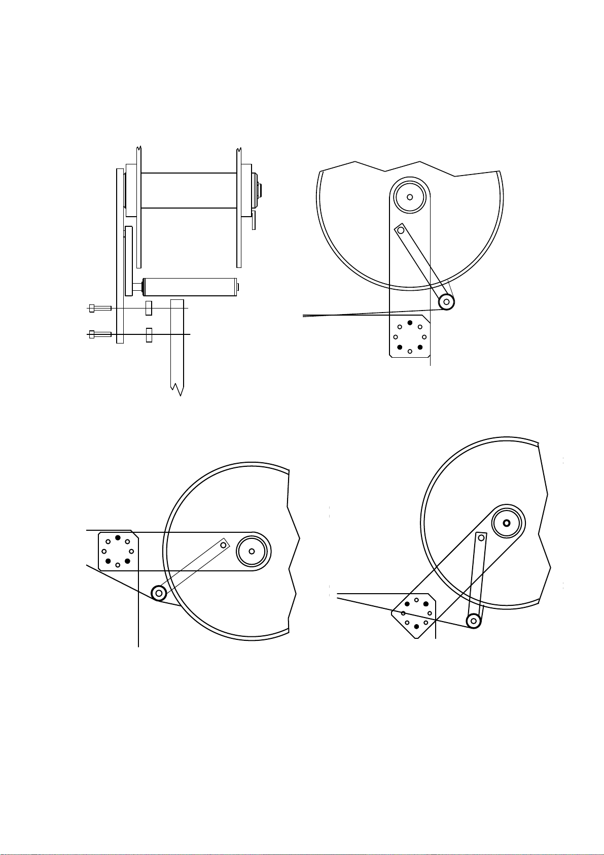
5.1. LABEL FORMAT SET UP PROCEDURE
(SEE PICTURES 5 and 7)
The printer retains the label length and the backing
paper transparency in permanent memory.
If changing label format or print media type
you have to use the following procedure to update the
values (see also paragraph 7.2):
1 - Switch the printer off.
2 - Lift the printing head up by rotating lever #25b.
3 - Thread the web between the printing roller and
the printing head #21,105.
4 - Lift the pressure roller up by rotating lever #17b.
5 - Thread the web between the driving roller and
the pressure roller #35,32 up to the rewinding
shaft #102.
6 - Check web has been rightly positioned under the
label photosensor #10.
7 - Lift the printing head and the pressure roller down
by rotating levers #25a and #17a.
8 - Switch the printer on while pushing the print
button.
9 - Printer ejects some labels (depending on their
length) and stores the values of the media.
10 - Release the print button.
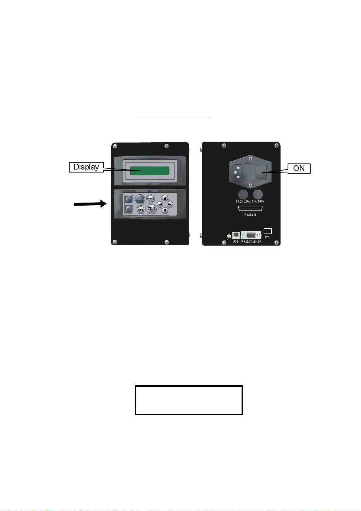
11 - The display lits light blue and the printer is ready
to work.
6. PRINTING MEDIA DESCRIPTION
6.1. PAPER SPECIFICATIONS
White coated glossy printing paper
- weight: 65 ÷ 90 g/mq (ISO536)
- caliper: 0,075 ÷ 0,083 mm (ISO534)
ADHESIVE SPECIFICATIONS
- peel adhesion(90° C): 430 N/m
- service temperature: -20° C ÷ + 70° C
LINER SPECIFICATIONS
- BG 40 brown, supercalendered glassine
- weight: 65g/mq (ISO536)
- caliper: 0.057 mm (ISO534)
- transparency: 45%
SUGGESTED MODELS
- Fasson Fasthermal NT
- Kanzaki KPT 86-H
- Fasson Fastransfer MP - S470 (TT models)
- Fasson Fastransfer Extra - S470 (TT models)
LABEL DIMENSIONS See Chapter 1
6.2. THERMAL RIBBON
SPECIFICATIONS
- film thickness 4.5 ÷ 6 micron
- core diameter: 25.4 mm
- width: 32 mm min/ 54 mm max.
- length: about 220 meters
- ink coating outside
SUGGESTED MODELS
- TOIKO C 250 (matt paper)
- TOIKO CR 150 (glossy paper and polypropylene)
- TOIKO R 300 (plastic media)
STORAGE
Keep labels and ribbons in a dry place at temperature
not over 40° C and not exposed to direct sun light.
7. THERMAL RIBBON AND LABEL ROLL REPLACEMENT
7.1. THERMAL RIBBON REPLACEMENT
(SEE PICTURE 7)
Remove the used roll. Remove the core #47 from the
shaft #30 and put it on the rewinder #29.
By rotating the lever #25b, lift the printing head #105
from the printing roller #21, setting the movement
of the ribbon free.
Slide new ribbon #43 onto shaft #30 and thread it
under the ribbon photosensor #48 and the threaders
#108, 107 and 37 and up round to the rewinder #29.
Attach the ribbon leader with label/tape to core #47.
Return head lever to closed position #25a
7.2. LABEL ROLL REPLACEMENT
(SEE PICTURE 5)
In case of changing of label format or printing media type, remember to follow the "Label format set up
procedure" shown on paragraph 5.1.
Remove the movable flange by rotating the lever #41.
Remove the empty label roll.
Insert new label roll onto roller #45
Reassemble the movable flange and push it tightly
against the side of the label roll; lock lever #41.
By rotating the lever #25b, lift the printing head #105
from the feed roller #21, setting the movement of
labels and ribbon free.
By rotating the lever #17b, lift the pressure roller #32
from the driving roller #35.
Remove clip #28 from the rewinding shaft #102.
Remove backing paper from the rewinding shaft.
Remove the first 50 centimetres from liner of the new
roll labels.
Hold pressure clip #33 up and feed the liner through
the path, thread the web between the printing roller
and the thermal head #21,105, then around the
driving roller and under the pressure roller #35,32,
finally slide the liner on the rewinder unit #102 and
fasten it with the clip holder #28.
Turn the rewinder to stretch the paper.
Turn head lever and toggle lever back to closed
positions #25a,17a.
Check paper has been rightly positioned under
the label photosensor #10.