Italtecnica Fluomac User manual

Istruzioni per l’uso Mode d’emploi
Owner’s manual Instrucciones para el uso
Bedienungsanweisung Instruções para o uso
ITALTECNICA S.r.l.
Viale Europa 31 35020 TRIBANO (Padova)
Italy
Telefo o ++39/049/9585388 – Fax ++39/049/5342439
E-mail: italtecnica@italtecnica.com Http://www.italtecnica.com

I
ISTRUZIONI PER L’USO
PARTI FUNZIONALI
1. Spia tensione di rete 5. Uscita con attacco filettato da
1” maschio
2. Spia arresto a secco 6. Vite di regolazione della
pressione di intervento
3. Tasto di RESET
4. Pressacavi 7. Ingresso con attacco filettato da
1” maschio
1. GENERALITÀ
Fluomac è un’apparecchiatura che consente di automatizzare l’avvio e
l’arresto di un’elettropompa in relazione rispettivamente
all’abbassamento della pressione (apertura rubinetti) e all’arresto del
flusso nell’impianto (chiusura rubinetti) in cui esso è montato. Assolve
inoltre all’importante funzione di arresto della pompa in mancanza
d’acqua, proteggendola così da dannosi funzionamenti a secco.
Si consiglia l’utilizzo di Fluomac in impianti dove sia certo il passaggio
di acqua priva di sedimenti. Se ciò non fosse possibile è necessario
installare un filtro in ingresso all’apparecchio.

!
I
LEGGERE ATTENTAMENTE IL PRESENTE FOGLIO ISTRUZIONI
PRIMA DELL’INSTALLAZIONE E DELLA MESSA IN FUNZIONE.
2. NORME DI SICUREZZA
Per evitare scosse elettriche e scongiurare il pericolo
d’incendio attenersi scrupolosamente a quanto segue:
•Prima di qualsiasi intervento sezionare l’apparecchio dalla
rete elettrica.
•Assicurarsi che la linea elettrica di allacciamento alla rete e le
eventuali prolunghe abbiano una sezione del cavo adeguata
alla potenza della pompa e che le connessioni elettriche non
siano raggiungibili dall’acqua.
•Utilizzare sempre un interruttore differenziale automatico con
IDn=30mA nel caso di impiego in piscine, laghetti o fontane.
ATTENZIONE: all’arresto della pompa le condotte risulteranno in
pressione, pertanto, prima di un qualsiasi intervento, sarà
opportuno aprire un rubinetto per scaricare l’impianto.
3. INSTALLAZIONE
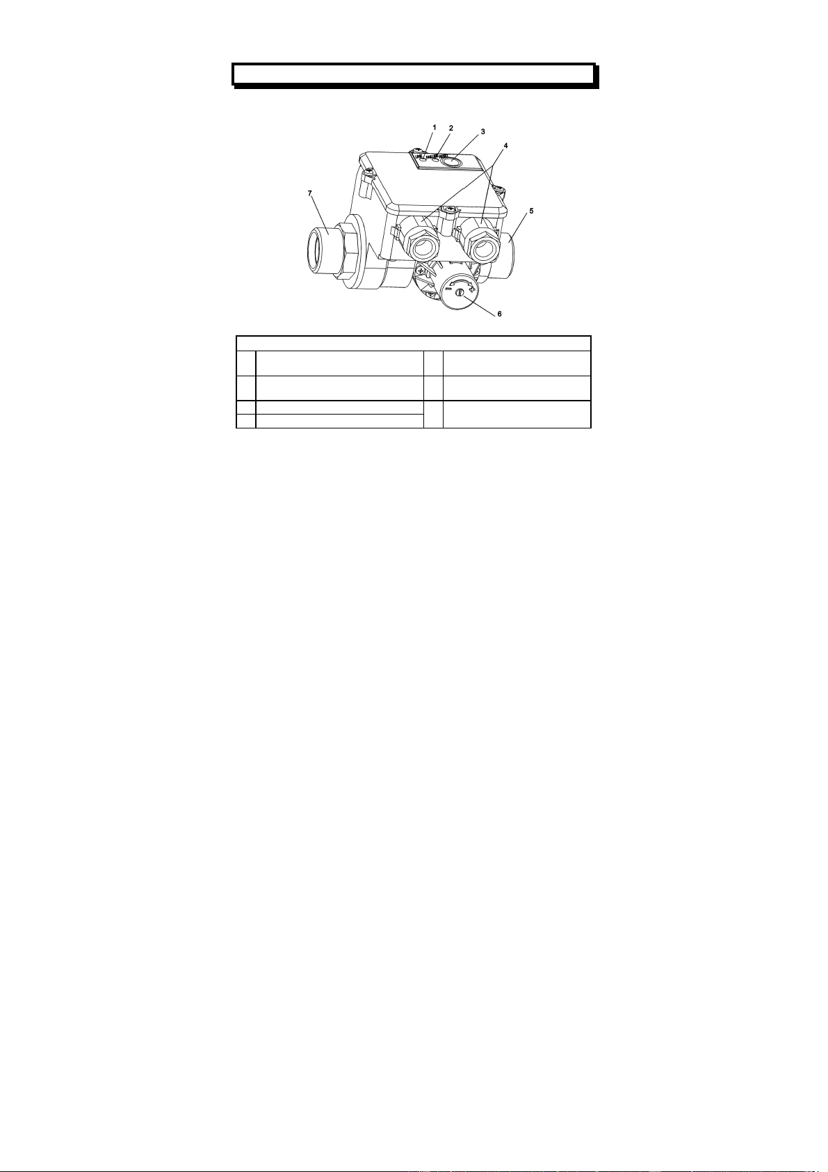
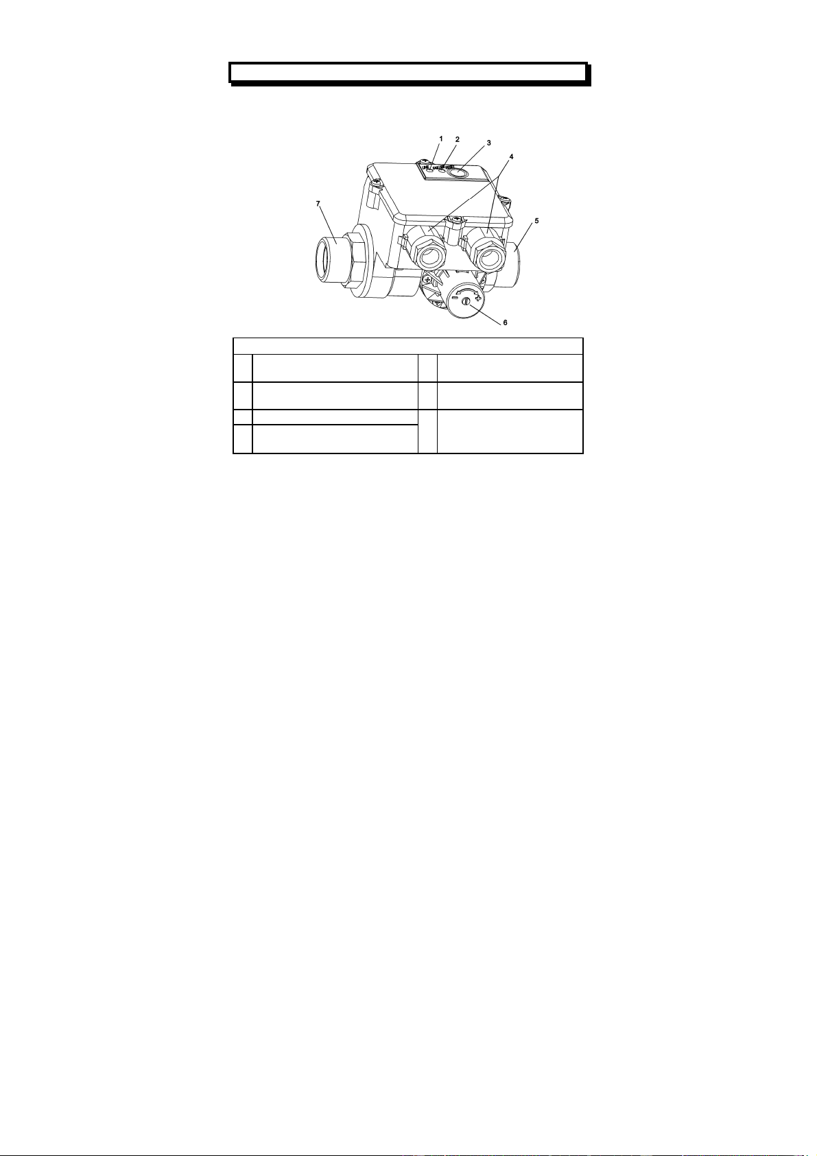
1. Installare l’apparecchio in un qualsiasi punto posto tra la mandata
della pompa ed il primo utilizzo in modo che la direzione della
freccia posta sul lato compreso tra i due attacchi da 1” corrisponda
alla direzione del fluido nella tubazione. Assicurarsi della perfetta
tenuta stagna delle connessioni idrauliche. Nel caso si utilizzi una
pompa con pressione massima superiore a 10 bar è necessario
installare un riduttore di pressione in ingresso all’apparecchio.
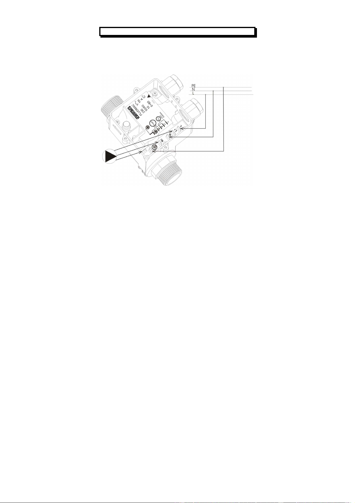
2. Per il collegamento elettrico della versione fornita senza cavi
attenersi allo schema riportato nel quadro interno o al disegno
seguente. Inoltre nel caso si utilizzi una pompa con potenza
superiore a ½ Hp. e la temperatura ambiente sia maggiore di 25°C
è necessario utilizzare per il cablaggio, cavi con resistenza termica
non inferiore a 99°C. Per il cablaggio dei Faston u tilizzare
esclusivamente l’apposita pinza. Nella versione con cavi di
collegamento inclusi è sufficiente connettere la spina di
alimentazione della pompa alla presa del Fluomac e
successivamente la spina di quest’ultimo ad una presa di corrente.

I
3. La pressione di intervento è preimpostata al valore 1,5 bar ottimale
per la maggior parte delle applicazioni; per ottenere pressioni di
intervento diverse agire sulla vite posta sulla flangia laterale
contrassegnata con i simboli + e -.
ATTENZIONE : PER UN CORRETTO FUNZIONAMENTO DEL
FLUOMAC E’ INDISPENSABILE CHE LA PRESSIONE MASSIMA
DELLA POMPA SIA SUPERIORE ALMENO DI 0,6 bar RISPETTO
ALLA PRESSIONE DI INTERVENTO.
4. PROCEDURA PER LA MESSA IN FUNZIONE
ATTENZIONE : nel caso in cui il livello dell’acqua da adescare sia
al di sotto del livello a cui è installata la pompa è obbligatorio
utilizzare un tubo di aspirazione dotato di valvola di fondo
antiriflusso che ne permette il riempimento alla prima messa in
funzione e ne impedisce lo svuotamento all’arresto della pompa.
1. Prima della messa in funzione riempire completamente il tubo di
aspirazione e la pompa ed attivare successivamente quest’ultima
dando alimentazione al Fluomac; all’arresto della pompa aprire il
rubinetto dell’impianto posizionato alla quota più elevata.
2. Se si ha flusso regolare in uscita dal rubinetto e funzionamento
continuo della pompa la procedura di messa in funzione è stata
completata con successo. Se non si ha presenza di flusso si può
provare a far funzionare con continuità la pompa per un tempo
superiore a quello di temporizzazione dell’apparecchio tenendo
premuto il tasto RESET. Se anche in questo caso il problema
persiste togliere alimentazione al Fluomac e ripetere la procedura
dal passo 1.
Arresto a secco : lo stato di arresto a secco è segnalato
dall’accensione della spia rossa FAILURE a motore spento. Per Il
ripristino dell’impianto è sufficiente premere il tasto RESET dopo aver
accertato la presenza d’acqua in aspirazione.

I
5. GARANZIA
La garanzia copre il prodotto per un periodo di 24 mesi dalla data
d’acquisto e viene riconosciuta se l’apparecchio non presenta
manomissioni e se sono state rispettate tutte le condizioni operative.

I
6. LE SOLUZIONI A PROBLEMI POSSIBILI
PROBLEMA POSSIBILI CAUSE SOLUZIONE
La pompa si attiva e
disattiva in continua_
zione.
L’impianto presenta
delle perdite. Controllare le varie
connessioni idrauliche.
Condizione di arresto
a secco anche in
presenza d’acqua in
aspirazione.
Pressione di inter_
vento troppo alta. Agire sulla vite 6 in senso
antiorario (-). Premere il
tasto RESET ed accertarsi
che all’arresto della pompa
la spia rossa risulti spenta.
La pompa non riparte. 1.Mancanza della ten_
sione di rete
2.Eccessivo dislivello tra
Fluomac ed uno degli
utilizzi (rubinetti).
3.La pompa è guasta
4.Anomalia Fluomac.
1.Controllare le connessioni
elettriche.
2.Agire sulla vite 6 in senso
orario (+) per aumentare la
pressione di intervento.
3.Rivolgersi ad un tecnico
di fiducia.
4.Rivolgersi al rivenditore.
La pompa non si
arresta. 1.L’impianto presenta
consistenti perdite.
2.Anomalia Fluomac.
1.Controllare l’impianto.
2.Rivolgersi al rivenditore.
7. DATI TECNICI
Alimentazione: . . . . . . . . . . . . . . . . . . . 110-230VAC ±10% 50/60Hz
Corrente max.: . . . . . . . . . . . . . . . . . . . . . . . . . . . . . . . . . . . . . . . . 10 A
Campo pressione di intervento: . . . . . . . . . . . . . . . . . . . . . . . 1÷3,5 bar
Pressione di intervento preimpostata: …………………………….. 1,5 bar
Pressione max. ammissibile: . . . . . . . . . . . . . . . . . . . . . . . . . . . . .10 bar
Temperatura max. liquido: . . . . . . . . . . . . . . . . . . . . . . . . . . . . . . . 55°C
Perdita di carico a 100l/min.: . . . . . . . . . . . . . . . . . . . . . . . . . . 0,7 bar
Connessioni: . . . . . . . . . . . . . . . . . . . . . . . . . . . . . . . . .1” GAS maschio
Su richiesta, ingresso 1” gas femmina girevole
Grado di protezione: . . . . . . . . . . . . . . . . . . . . . . . . . . . . . . . . . . . .IP 54
Tipo (Rif. EN 60730-1): …………………………………………………..1.B

GB
INSTRUCTIONS FOR USE
FUNCTIONAL PARTS
1.
Grid voltage indicator 5.
Outlet with 1” male
threaded connection
2.
Dry stop indicator 6.
Operating pressure setting
screw
3.
RESET button
4.
Cable clamps 7.
Inlet with 1” male threaded
connection
1. FEATURES
Fluomac is designed to automatize the starting and stopping operations
of an electric pump with regard to a drop in pressure (opening of the
taps) and to the stopping of the flow through the system (closing of the
taps), respectively. Furthermore, Fluomac stops the pump when senses
the lack of water flow, preventing it from any damaging dry operation.
It is advisable using Fluomac with water systems whose water is
without sediments. In case it is not possible, it is necessary to install a
filter before the inlet of the device.

!
GB
PLEASE READ THIS INSTRUCTION LEAFLET CAREFULLY
THROUGH BEFORE INSTALLING AND OPERATING THE DEVICE.
2. SAFETY REGULATIONS
To avoid shocks and fire risks, read and follow closely the
following instructions:
•Always unplug the device from the mains before carrying out
any work on it.
•Be sure that the electric line connecting the device to the
mains and the extension leads have a cross-section suitable
for pump power and be sure that the electrical connections
are far away from any water source.
•When Fluomac is used for swimming pools, ponds and
fountains it is necessary to use an automatic RCD with
IDn=30mA protection.
WARNING: when the pump stops the pipes are under pressure
consequently we recommend opening a tap to discharge the
system before carrying out any work.
3. INSTALLATION
1. Install Fluomac anywhere between the pump and the first service
outlet so that the arrow on the case is pointing in the same
direction as the fluid flowing through the pipe. Check perfect water
tightness of all water connections. If you are using a pump with a
pressure higher than 10 bar, install a pressure reducer on the
Fluomac’s inlet.
2. For the electrical connection of the version supplied without
electric leads, follow the wiring diagram on the printed circuit board
cover. Furthermore, in case of use of a pump with power higher
than ½ Hp and the ambient temperature is higher than 25°C it is
necessary to wire Fluomac with cables with a thermic resistance
not inferior to 99°C.Use only suitable wire nippers to wire the
Fastons. If the leads are included, simply connect the pump’s
power plug to the Fluomac socket and its own power plug to a
current outlet.

GB
3. Operating pressure is pre-set at 1.5 bar which is the optimum
value for the majority of applications. Minimum operating pressure
can be adjusted as needed by turning the screw situated on the
side flange marked with + and -.
WARNING: TO ENSURE CORRECT WORKING OF THE FLUOMAC,
MAXIMUM PUMP PRESSURE MUST BE AT LEAST 0,6 BAR
HIGHER THAN FLUOMAC OPERATING PRESSURE.
4. STARTING FLUOMAC
WARNING: whenever the level of the priming water is lower than
the level of the water where the pump is placed, a suction line
equipped with an antibackflow foot valve is absolutely essential.
This valve allows the line to be filled when it is first used and
prevents it from being emptied when the pump stops.
1. Before turning on, fill up the suction pipe and pump with water and
then start the pump by connecting the Fluomac power plug to a
current outlet; when the pump stops open the tap situated higher
up.
2. Installation is correct if the flow from the tap is regular and if the
pump works continuously. If there is no water you can try to make
the pump work without interruption - for a period of time longer
than the device’s working time - by keeping the RESET button
depressed. If the problem persists, disconnect the Fluomac and
repeat the procedure from point 1.
Dry stop: The red FAILURE LED lits up with motor off to indicate a
dry stop. To start the system again press the RESET button after
having checked the presence of water in the suction pipe.

GB
5. WARRANTY
The warranty is valid for a period of 24 months starting from the
purchasing date. The warranty is acknowledged if the device shows no
signs of tampering and if all the manufacturer’s instructions were
followed during the installing and operating phases.

GB
6. POSSIBLE PROBLEMS
PROBLEM POSSIBLE CAUSES SOLUTION
The pump switches
on and off
continuously.
Leaks in the system. Check all hydraulic
connections.
Dry stop even if
there is water in the
suction pipe.
Operating pressure too
high.
Turn screw 6
anticlockwise (-)
direction. Press the
RESET button and make
sure the red light is off
when the pump stops.
The pump do not
start again. 1.Mains voltage failure.
2.The drop between the
Fluomac and one of the tap
is too great.
3.The pump is out of order.
4.Fluomac is
malfunctioning.
1.Check the electrical
connections.
2.Turn screw 6 in
clockwise (+) to increase
the operating pressure.
3.Consult an electrician.
4.Consult your dealer.
The pump does not
stop. 1.There are big leaks in the
system.
2.Fluomac is
malfunctioning.
1.Check the system.
2. Consult your dealer.
7. TECHNICAL DATA
Power source: . . . . . . . . . . . . . . . . . . . 110-230 VAC ±10% 50/60Hz
Max. current: . . . . . . . . . . . . . . . . . . . . . . . . . . . . . . . . . . . . . . . . . .10 A
Operating pressure range: . . . . . . . . . . . .. .. 1÷3,5 bar / 14.5÷50,65 psi
Pre-set operating pressure: …………………………….. 1,5 bar / 21,8 psi
Max. allowable pressure: . . . . . . . . . . . . . . . . . . . . . . . . 10 bar / 145 psi
Max. liquid temperature: . . . . . . . . . . . . . . . . . . . . . . . . . . . .55°C/130°F
Pressure Drop to 100l/min: . . . ... . . . . . . . . . . . . . . . . . . . .... . . .0,7bar
Connections: . . . . . . . . . . . . . . . . . . . . . . . . . . . . . . . .. . . . 1” GAS male
Protection level: . . . . . . . . . . . . . . . . . . . . . . . . . . . . . . . . . . . . . . . IP 54
Type (Re. EN 60730-1): ……………………………………………….... 1.B

D
BEDIENUNGSANLEITUNG
FUNKTIONSTEILE
1.
Kontrollampe für Netzspannung
5.
Auslauf mit 1”
Aussengewindeanschluss
2.
Kontrollampe für Anhalten bei
Trockenlauf 6.
Verstellschraube des
Ansprechdrucks
3.
RESET-Taste
4.
Kabelhalter 7.
Einlauf mit 1”
Aussengewindeanschluss
1. ALLGEMEINES
Bei Fluomac handelt es sich um ein Gerät, mit dem das Anlassen und
das Anhalten einer Elektropumpe je nach Senkung des Drucks (Öffnen
der Hähne) und Anhalten des Wasserstroms in der Anlage (Schließen
der Hähne), in die es eingebaut ist, automatisiert werden kann. Es hat
außerdem die wichtige Aufgabe, die Elektropumpe bei Trockenlauf oder
Wassermangel abzuschalten und diese somit vor schädlichem
Trockenbetrieb zu schützen.
Fluomac wird für anlagen empfohlen, in denen das durchfließende
Wasser bestimmt ohne ablagerungen ist. Im gegenteiligen Fall muss
ein Filter am einlauf zum Gerät eingebaut werden.

!
D
DIESE ANLEITUNG VOR DER INSTALLATION UND DER
INBETRIEBSETZUNG GENAU LESEN.
2. SICHERHEITSVORSCHRIFTEN
Um elektrische Schläge zu vermeiden und Brandgefahr
vorzubeugen, das folgende genauestens beachten:
•Das Gerät vor jedem Eingriff vom Stromnetz abschalten.
•Sicherstellen, dass die Anschlussleitung an das Stromnetz und
eventuelle Verlängerungen einen Kabelschnitt haben, der für
die Leistung der Pumpe geeignet ist, und dass die elektrischen
Anschlüsse nicht vom Wasser erreicht werden können.
•Im Fall von Gebrauch in Schwimmbädern, Teichen oder
Brunnen immer einen automatischen Differentialschalter mit
IDn=30mA verwenden.
ACHTUNG: beim Anhalten der Pumpe werden die Leitungen unter
Druck stehen; daher sollte vor jedem Eingriff ein Hahn geöffnet
werden, um die Anlage zu entladen.
3. INSTALLATION
1. Das Gerät an einem beliebigen Punkt zwischen dem Auslass der
Pumpe und dem ersten Abnehmer installieren, so dass die
Richtung des Pfeils auf der Seite zwischen den zwei 1”
Anschlüssen mit der Richtung der Flüssigkeit in der Rohrleitung
übereinstimmt. Sicherstellen, dass die hydraulischen
Verbindungen vollkommen dicht sind. Falls eine Pumpe mit
Höchstdruck über 10 bar benutzt wird, muss ein Druckreduzierer
am Eingang des Geräts installiert werden.
2. Für den Elektroanschluss der ohne Kabel gelieferten Ausführung,
nach dem Plan auf dem Deckel der elektronischen Steuerkarte
vorgehen. Falls eine Pumpe mit Leistung über ½ HP verwendet
wird und die Raumtemperatur höher als 25°C ist, müssen Kabel
mit Wärmebeständigkeit nicht unter 99°C für die Verdrahtung
verwendet werden. Für die Verdrahtung der Faston ausschließlich
die dazu bestimmte Zange benutzen. Bei der Ausführung mit
mitgelieferten Anschlusskabeln genügt es, den
Versorgungsstecker der Pumpe mit der Steckdose des Fluomac
zu verbinden, dann den Stecker des Fluomac mit einer Steckdose
des Stromnetzes verbinden.

D
3. Der Druck, bei dem das Gerät anspricht, ist auf 1,5 bar
voreingestellt; dieser Druck ist für die meisten Anwendungen
optimal. Für einen anderen Ansprechdruck die Schraube mit den
Zeichen + und – am seitlichen Flansch betätigen.
ACHTUNG: FÜR EINEN KORREKTEN BETRIEB DES FLUOMAC
MUSS DER HÖCHSTDRUCK DER PUMPE MINDESTENS 0,6 BAR
HÖHER ALS DER ANSPRECHDRUCK SEIN.
4. VERFAHREN FÜR DIE INBETRIEBSETZUNG
ACHTUNG: sollte der Ansaugwasserstand unter der
Installationshöhe der Pumpe sein, ist es Pflicht, ein Ansaugrohr
mit Boden-/Rückschlagventil zu benutzen, welches das Füllen der
Pumpe bei der ersten Inbetriebsetzung gestattet und ihr Entleeren
beim Anhalten verhindert.
1. Vor der Inbetriebsetzung das Ansaugrohr und die Pumpe ganz
füllen, dann die Pumpe einschalten und den Fluomac speisen;
beim Anhalten der Pumpe den Hahn der Anlage öffnen, der sich
am höchsten Punkt befindet.
2. Die Inbetriebsetzung ist erfolgreich beendet, wenn das Wasser
regelmäßig aus dem Hahn ausläuft und die Pumpe mit
Dauerbetrieb arbeitet. Sollte kein Wasser ausfließen, kann
versucht werden, die Pumpe länger als die am Gerät eingestellte
Zeit auf Dauerbetrieb arbeiten zu lassen, wobei die Taste RESET
gedrückt werden muss. Sollte das Problem auch danach weiter
vorhanden sein, die Stromversorgung zum Fluomac abschalten
und das Verfahren ab Schritt 1 wiederholen.
Anhalten bei Trockenlauf: das Anhalten bei Trockenlauf wird durch
das Einschalten der roten Kontrollampe FAILURE bei abgeschaltetem
Motor gemeldet. Zur Rückstellung der Anlage genügt es, die Taste
RESET zu drücken, nachdem sichergestellt wurde, dass Wasser in der
Ansaugung vorhanden ist.

D
5. GARANTIE
Die Garantie deckt das Produkt für 24 Monate ab Kaufdatum. Sie ist nur
gültig, falls das Gerät keine Beschädigungen aufweiset und alle
Betriebsbedingungen eingehalten worden sind.

D
6. MÖGLICHE PROBLEME
PROBLEM MÖGLICHE
URSACHEN LÖSUNG
Die Pumpe
schaltet sich
dauernd ein und
aus.
Die Anlage weist
Leckagen auf. Die verschiedenen
hydraulischen Verbindungen
überprüfen.
Anhalten wie bei
Trockenlauf,
obwohl Wasser in
der Ansaugung
vorhanden ist.
Zu hoher
Ansprechdruck. Die Schraube 6 gegen den
Uhrzeigersinn betätigen (-).
Die Taste RESET drücken
und sicherstellen, dass die
rote Kontrollampe beim
Anhalten der Pumpe
ausgeschaltet ist.
Die Pumpe setzt
sich nicht mehr in
Betrieb.
1. Keine Netzspannung
vorhanden.
2. Zu großer
Höhenunterschied
zwischen dem Fluomac
und einem der
Abnehmer (Hähne).
3. Die Pumpe ist defekt.
4. Betriebsstörung des
Fluomac.
1. Die Elektroanschlüsse
überprüfen.
2. Die Schraube 6 in den
Uhrzeigersinn betätigen (+),
um den Ansprechdruck zu
erhöhen.
3. Sich an einen
Fachtechniker wenden.
4. Sich an den Händler
wenden.
Die Pumpe hält
nicht an. 1. Die Anlage weist
größere Leckagen auf.
2. Betriebsstörung des
Fluomac.
1. Die Anlage überprüfen.
2. Sich an den Händler
wenden.
7. TECHNISCHE DATEN
Betriebsspannung: ......…………..……….110-230 VAC ± 10% 50/60 Hz
Nennstrom: …………...………………………………………………... 10 A
Einschaltdruck: ………………………………………………….. 1÷3,5 bar
Eingestelter Anlaßdruck: ............................................................. 1,5 bar
Max. Betriebsdruck: ...........………………………………………....10 bar
Wassertemperatur, max.: ……............…………………………...….55°C
Gefällverlust 100 l/min……………………………………………….0,7 bar
Anschlüsse: ………………………….. 1” Gasanschluss, Außengewinde
Schutzart: ………………………………………………………….……IP 54
Type (Re. EN 60730-1) ……………………………………………….…1.B

F
MODE D’EMPLOI
PARTIES DE FONCTIONNEMENT
1. Voyant de tension de secteur 5. Sortie avec raccord fileté 1”
mâle
2. Voyant d'arrêt à sec 6. Vis de réglage de la pression
d’intervention
3. Touche de RESET
4. Passe-câble 7. Entrée avec raccord fileté 1”
mâle
1. DESCRIPTION GENERALE
Fluomac est un appareil qui permet d’automatiser la mise en marche et
l'arrêt d’une électropompe, relatifs, respectivement, à la baisse de
pression (ouverture des robinets) et à l’interruption du flux dans
l’installation (fermeture des robinets) sur laquelle la pompe a été
montée. Il remplit également la fonction importante d'arrêt à sec en
désactivant la pompe en cas de manque d’eau, ce qui la protège contre
les dommages provoqués par un fonctionnement à sec.
On conseille d’utiliser Fluomac dans des installations où le passage
d’eau est sans sédiments. S’il n’est pas possible, il faut installer un filtre
en entrée de l’appareil.

!
F
LIRE ATTENTIVEMENT CETTE NOTICE AVANT L’INSTALLATION
ET LA MISE EN SERVICE.
2. CONSIGNES DE SECURITE
Pour éviter tout risque électrique et d’incendie, se conformer
scrupuleusement aux indications suivantes:
•Avant toute intervention, débrancher l’appareil du secteur.
•S’assurer que la section des câbles de la ligne électrique de
branchement au secteur et des éventuelles rallonges ont une
section adéquate et que l‘eau ne peut pas arriver aux
connexions électriques.
•Toujours utiliser un disjoncteur différentiel automatique avec
IDn=30 mA.
ATTENTION : quand on arrête la pompe, les conduites sont sous
pression; avant toute intervention, il est donc nécessaire d’ouvrir
un robinet pour faire tomber la pression dans l’installation.
3. INSTALLATION
1. Installer l’appareil en un point quelconque entre le refoulement de
la pompe et le premier point d’utilisation de sorte que la direction
de la flèche située sur le côté compris entre les deux raccords de
1" corresponde à la direction du fluide de la conduite. S’assurer
que les raccordements hydrauliques sont parfaitement étanches.
Si l’on utilise une pompe ayant une pression maximum supérieure
à 10 bars, il est nécessaire d’installer un réducteur de pression à
l’entrée de l’appareil.
2. Pour le branchement électrique du modèle fourni sans câbles, se
conformer au schéma indiqué sur le cache de la carte
électronique. En autre, si on utilise une pompe de puissance
supérieure à ½ CV et la température ambiante est plus de 25°C il
est nécessaire d’utiliser pour le câblage des câbles avec une
résistance thermique de minimum 99°C. Pour le câbla ge des
faston, utiliser exclusivement la pince prévue à cet effet Pour le
câblage des faston, utiliser exclusivement la pince prévue à cet
effet. Pour les modèles avec câbles de branchement inclus, il suffit
de brancher la fiche électrique de la pompe à la prise du Fluomac
puis la fiche de ce dernier à une prise de courant.

F
3. La pression de mise en marche est préréglée à 1,5 bar, valeur
optimale pour la plupart des applications; pour obtenir des
pressions de mise en marche différentes, tourner la vis située sur
la bride portant les signes + et -, qui se trouve sous le couvercle.
ATTENTION: POUR UN FONCTIONNEMENT CORRECT DE
FLUOMAC, IL EST INDISPENSABLE QUE LA PRESSION MAXIMUM
DE LA POMPE SOIT SUPERIEURE D’AU MOINS 0,6 BAR A LA
PRESSION DE MISE EN MARCHE.
4. PROCEDURE POUR LA MISE EN SERVICE
ATTENTION: si le niveau de l’eau à pomper est au-dessous du
niveau auquel la pompe est installée, il est obligatoire d’utiliser un
tuyau d’aspiration équipé d’un clapet crépine qui garantit le
remplissage de la pompe lors la première mise en service et
l’empêche de se vider au moment de l'arrêt.
1. Avant la mise en service, remplir complètement le tuyau
d’aspiration et la pompe puis la mettre en marche en activant le
Fluomac; pour l’évacuation totale de l’air, ouvrir le robinet de
l’installation positionné au niveau le plus haut.
2. Si l’on a un écoulement régulier à la sortie du robinet et un
fonctionnement continu de la pompe, cela indique que la
procédure de mise en service a été correctement exécutée. En
cas d’absence d’écoulement, on peut essayer de faire fonctionner
la pompe en continu pendant une période supérieure à celle de la
temporisation de l'appareil en maintenant le bouton de
réarmement manuel enfoncé. Si le problème persiste malgré tout,
débrancher le Fluomac et répéter la procédure depuis le début.
Arrêt à sec: le voyant rouge FAILURE allumé avec le moteur arrêté
signale l'arrêt à sec. Pour remettre l’installation en service, il suffit
d’appuyer sur le bouton de réarmement manuel après s'être assuré qu’il
y a de l’eau en aspiration.

F
5. GARANTIE
La garantie couvre le produit pendant une période de 24 mois à
compter de la date d’achat et n’est reconnue que si l’appareil n’a pas
été modifié et si toutes les conditions de fonctionnement ont été
respectées.
This manual suits for next models
1
Table of contents
Languages:
Other Italtecnica Switch manuals