ITC 44-010 User manual

ESPAÑOL
Cl2SENSOR


CONTENTS
1.-GENERAL DESCRIPTION 4
2.-TRANSPORT AND HANDLING 4
3.-TECHNICAL FEATURES 5
4.-OPERATION 6
5.-INSTALLATION 7
5.1 Installation in the Multifunction Sensor Holder Red. 44-020 7
5.2 Connections 7
6.- START-UP 8
6.1 Sensor Conditioning 8
6.2 Sensor Calibration 8
7.- MAINTENANCE 9
7.1 Cleaning and Calibration 9
7.2 List of Parts 10
7.3 Electrode head replace 11
7.4 Problem-Cause-Solution 12
CE DECLARATION OF CONFORMITY 15
WARRANTY 15
SAFETY RULES
In order to prevent personal risks and damages to the environment and to
ensure the proper operation of the system, the staff in charge of the systems
installation, start-up and maintenance should follow, the instructions of this
manual, paying special attention to the explicitly detailed recommendations and
warning. They should also follow the specific instructions on the chemical
products to be dosed.

1.-GENERAL DESCRIPTION
.
Free chlorine amperometric sensor for drinking water and water treatment. Specifically
designed to determine the residual level of inorganic chlorine in water.
The chlorine sensor is of the open cell type with no intermediate liquids for the electroche-
mical reaction, thus facilitating installation and maintenance. Since it is an open sensor it
can be used in pressure applications and with solids in suspension.
Manufactured from materials that ensure perfect operation in applications such as:
- Drinking water desininfection
- Industrial processes
- Cooling towers
- Wastewaters reuse
The original packaging is designed to ensure that the transport and the storage of the
system can be carried out without causing damages to the systems provided these
processes are performed inside dry ventilated areas and away from sources of heat.
The packagin includes:
Free chlorine sensor
Instruction manual
2.- TRANSPORT AND HANDLING
4

3.-TECHNICAL FEATURES
- Potentiostatic amperometric sensor for measuring free chlorine
- Analyzable products: Cl2, NaClO, Ca(ClO)2
- Four- electrode system:
Working Electrode (Au)
Reference Electrode (Ag/AgCl)
Counter electrode (Au)
GND Electrode (Au)
-Scale reading 0.02-3.00 mg/l
- Precision: ± 2%
- WorKing conditions:
pH 6.5-9.0
Temperature 0-40ºC
Salinity: < 500 ppm Cl-, <500 ppm SO4
2-
Conductivity: 50 - 3000 uS/cm
Maximum pressure: 6 bar
- Polarization time: 30’ approx.
- Electrode cleaning: electrochemichal (WTR PRO control device)
- Protection: IP68
- Materials:
Body: PVC
Hydrodynamic regulator: PMMA
Sealing: FPM
5

Amperometric analysis is based on the measurement
of current intensity. This intensity is produced by the
oxidation or reduction of an analyte when a suitable
voltage is applied.
In the case of free chlorine analysis:
As can be deduced from the above reaction, current intensity is proportional to the
amount of hypochlorous acid which is present in the measured solution.
The chlorine reduction takes place in the gold
working electrode (W) in which the suitable voltage is
applied referred to in the reading we obtain from the
reference electrode (R) Ag/AgCl. The electrical circuit
is completed by using a gold auxiliary electrode
(counterelectrode)(C). Finally, since the intensities
generated are very low (in the nanoampere range), a
fouth electrode in used in order to keep the signal as
stable as possible. This electrodes also made of gold
acts as a ground connection to eliminate any residual
current that might be found in the water.
It is important to bear in mind that hypochlorous acid is a weak acid and thus the
distribution of its species greatly depends on the pH of the water.
At the working voltage, the amperome-
tric sensor responds not only to hypo-
chlorous acid but also to hypochlorite.
For this reason it is fundamental that the
sensor response be compensated in
accordance with the pH of the medium.
With the WTRpro system, this correction
is automatically carried out in the pH
range of 6.5 to 9.0.
Outside this pH range, parasitic reations
on the electrode surfaces make it
impossible to correct the readings
generated.
4.-OPERATION
+ - -
HClO + H + 2e Cl + H O
2
E
RE CEWE
A
ClO-Cl-
H2O O2
RE CEWERE CEWE
A
ClO-Cl-
H2O O2
V
0
10
20
30
40
50
60
70
80
90
100
4 5 6 7 8 9 10 11
pH
%
% HClO
%ClO-
R
CW
GND
6
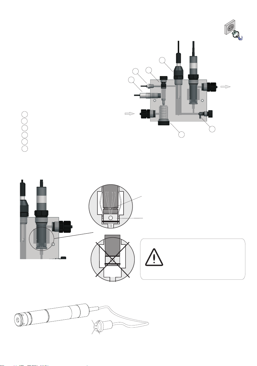
5.- INSTALLATION
1
2
3
4
5
6
1 Flow regulator
2 Cavity for temperature sensor
3 Flow detector
4 Input filter
5 Sampler
6 pH sensor cavity
ok
no
5.1 INSTALLATION IN MULTIFUNCTION SENSOR HOLDER REF. 44-020
HYDRODYNAMIC REGULATOR
AIR OUTLET
5.2 CONNECTIONS
1
2
4
3
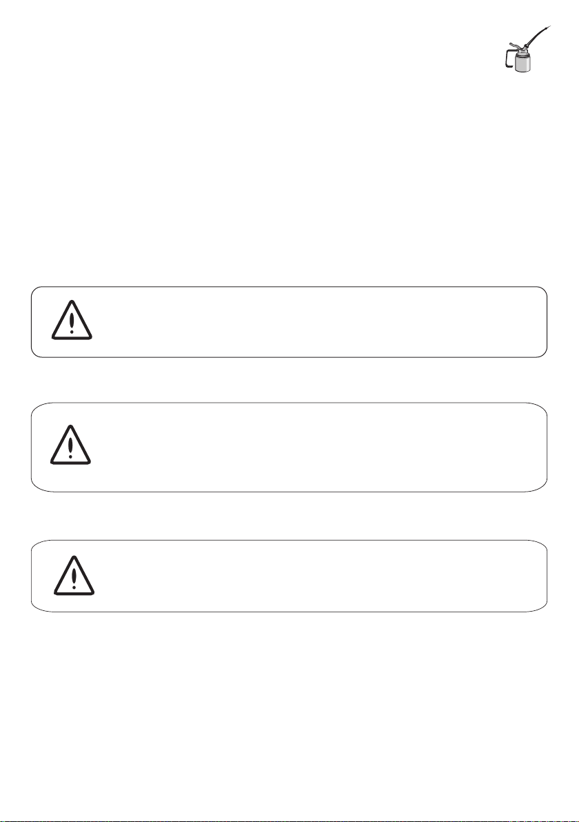
Working electrode
Reference electrode
GND
Counter electrode
12
3
4
The sensor must be installed where it is
possible to ensure a constant flow of
water with no chance of air bubbles
forming in the measuring cell.
It is recommended that it be installed in
the Multifunction Sensor Holder (Ref.
44-020), especially designed for this
application, and equipped with the
following:
Make sure there are no air
bubbles at the bottom of
the chlorine sensor.
7

If it has not been used recently or if it is being connected for the first time, the sensor will
require a conditionning time. Prior to sensor calibration, insert the sensor correctly into the
sensor holder and let the water containing free chlorine flow for 24 hours to ensure that the
cell is properly polarized. If the system start up can not be delayed 24 hours, wait one hour
before calibration, and repeat the calibration after 24 hours.
First point calibration: 0 mg/l
Once the sensor is properly conditioned let the water flow at 0 ppm until a stable
reading is achieved.
To facilitate the calibration at 0 mg/l, the user should have an active carbon filter
in by-pas before the sensor holder. This makes it possible to easily have the
qater at 0 ppm.
Second point calibration:
Let the water with free chlorine flow for ten minutes.
Take a sample of the water, do a DPD-1 analysis in order to determine the free
chlorine level of the sample, and introduce this value into the control device.
6.- START-UP
6.1 SENSOR CONDITIONING
6.2 SENSOR CALIBRATION
8
Cleaning interval:
Every 8 hours and after working for several hours without flow, with water without free
waste chlorine, or over 3 mg/l. This cleaning frequency is maintained automatically with
the WTR PRO control device.
Calibration interval:
The first time, after 24 hours.
This will subsequently depend on the water conditions: 1-4 weeks
After disconnecting the system, wait 60 minutes for the correct polarization
of the sensor. Calibrate, and after 24 hours repeat the calibration.
If the sensor has been working at 0 mg/l, without water flow, or without
water, for 1 hour or more, an electrochemical cleaning will have to be
Carried out. Then condition and calibrate the sensor once again.
The sensor can be passivated if it has been working for hours
over 3 mg/l. Clean the sensor introducing it into a HCI 0.1M solution for
20 seconds. Then conditioning and calibrate again the sensor.
7.- MAINTENANCE
7.1 CLEANING AND CALIBRATION
9

62300
64349
64410
44106
44104
CODE NAME
44-015 Chlorine sensor electrode head
44-016 Chlorine sensor body
44104 Ring holder for electrodes base
44106 Hydrodynamic regulator
62300 O-Ring 19x3 FPM
64349 O-Ring 14x2.5 FPM
64410 O-Ring 19x2 FPM
44-016
44-015
7.2 LIST OF PARTS
10
Table of contents


