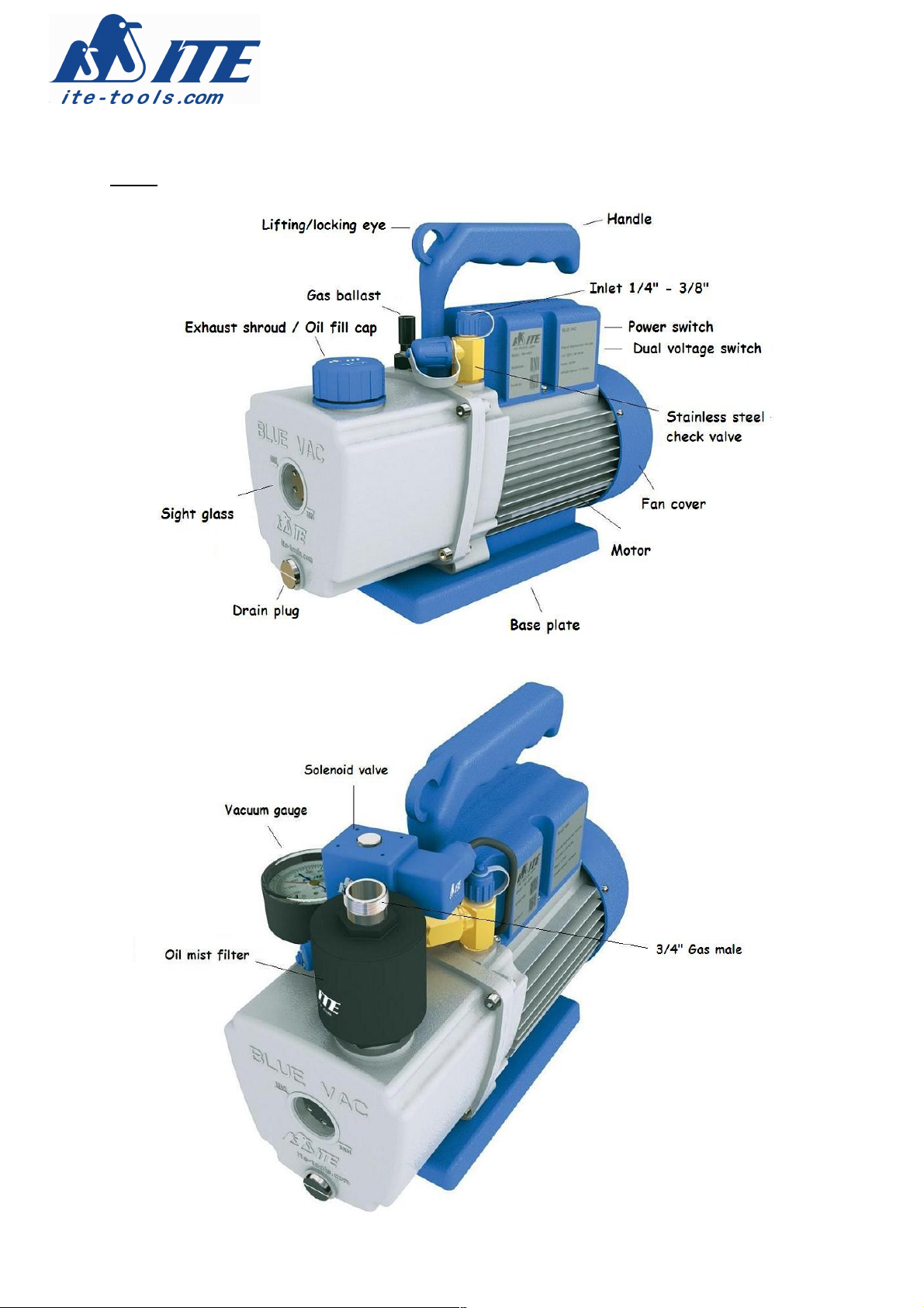
ITE MK-40-DS User manual

ITE Vacuum pumps
Instruction manual

Table of contents
Safety guidelines 3
Oil filling 3
Oil change 3
Gas ballast 3
General operation 4
Parts 5
Specifications 6
Warranty 7

3
Safety guidelines
∗After factory run-in and testing the pu p is drained of oil to prevent spillages during
ship ent - Do not operate the pu p until filled with oil.
∗Do not use the pu p to evacuate co bustible, explosive or poisonous gases.
∗Do not use the pu p to evacuate gases that contain particles, dust or stea .
∗The te perature of the evacuated gas should not exceed 80°C.
∗Do not use the pu p to transfer liquid or to co press gases.
∗Do not block the air outlet when the pu p is operating.
∗Do not operate the pu p in the rain or any other wet environ ent.
Oil filling
Ensure that the correct a ount of oil is used to fill the pu p (see specifications). Only ITE
vacuu pu p oil should be used as any other oil type ay affect perfor ance and could da age
your pu p.
1. Re ove the exhaust shroud fro top front of pu p and the cap fro the intake fitting.
2. Pour 50 l of oil into exhaust hole and then start the pu p for a few seconds with the intake
sealed.
3. Stop the pu p and continue filling until the oil level co es 3/4 of the way up the oil level
window located on the front of the pu p. DO NOT OVERFILL.
4. Please note that the oil level should be checked only when the pu p is running. When the
pu p is stopped the oil level of a correctly filled pu p will fall below the 1/2 way level in the
sight glass.
Oil change
Conta inants pulled fro a syste can affect vacuu pu p perfor ance and seriously da age
internal pu p parts so therefore frequent oil changes are reco ended. The pu p should be hot
when draining oil and if the pu p is not to be used for a long period of ti e always drain and refill
the pu p with fresh oil before using.
1. Re ove the drain plug at the botto of the front end of the pu p in order to drain the used
oil into a suitable receptacle with pu p running.
2. Refitt the drain plug and refill the pu p following the OIL FILLING procedure above.
Gas ballast
The gas ballast valve is used to help prevent condensation of conta inant vapors within the pu p.
Opening the valve ste (knurled rod located on top of pu p) allows relatively dry air fro the
at osphere to enter the pu p.
This air co bines with the wet vapor passing through the pu p and helps prevent the oisture
fro condensing and ixing with the vacuu pu p oil. To use the gas ballast valve slightly open
the valve during the first few inutes of syste pull-down and then close fully to allow the pu p
to achieve ulti ate vacuu .

4
General operation
The vacuu pu p is supplied with the following standard accessories.
1. An electrically operated solenoid valve which can easily be connected onto the inlet of the
vacuu pu p. This solenoid valve will ensure that the vacuu is aintained in the event of
power to the pu p being interrupted.
2. A vacuu gauge that allows you to check the depth of vacuu in the syste after evacuation
and also onitor for syste leaks.
3. An oil ist filter. This filter will avoid that excessive oil vapour will be exhausted fro the
pu p when evacuating large a ounts of air.
4. A non return valve on the inlet to prevent oil igrating fro the pu p into the evacuated
syste when the pu p is turned off.
5. A dual voltage switch allows an easy change fro 220V to 110V operation.
6. A 180 c (72”) charging hose to connect the pu p to a anifold gauge set or to the syste to
be evacuated.
7. The electric otor has ther al and electric overload protection to prevent the windings fro
da age if the electric otor beco es too hot or if the current gets too high, due to seizer or
other echanical da age.
8. The pu p is dual cycle and will operate on both 50 Hz and 60 Hz.
The ini u cold start te perature of the pu p is 0°C and below this te perature an external
heater should be used to a guarantee trouble free start up.
An optional anifold bracket can be supplied which is fitted to the pu p handle and this enables
quick and easy attach ent of a 1, 2, 4 or 5 valve anifold to the pu p.
The pu p can be supplied with different types of electrical connections/plugs. Please specify
odel requested.
The pu p can be used on all CFC, HCFC and HFC refrigeration syste s and for continuous use on
CFC and HCFC syste s ITE-205-P ineral vacuu pu p oil is reco ended.
For use on HFC syste s, we reco end the use of ITE-500-P ester oil.


6
Specifications
Model MK-40-DS MK-60-DS
Voltage 220 V/50Hz 110 V/60Hz 220 V/50 Hz 110 V/60 Hz
Free air displacement 40 L/ in 48 L/ in 66 L/ in 78 L/ in
1.44 CFM 1.70 CFM 2.30 CFM 2.75 CFM
Ultimate vacuum 15 icron 15 icron 15 icron 15 icron
0.020 Bar 0.020 Bar 0.020 Bar 0.020 Bar
Motor 0.19 kW 0.19 kW 0.25 kW 0.25 kW
1/4 HP 1/4 HP 1/3 HP 1/3 HP
Motor Speed 1440 RPM 1720 RPM 1440 RPM 1720 RPM
Oil capacity 350 l 350 l 380 l 380 l
Dimensions 330 x 135 x 255 350 x 143 x 265
Net weight 9,80 kg 11,50 kg
Model MK-120-DS MK-180-DS
Voltage 220 V/50Hz 110 V/60Hz 220 V/50 Hz 110 V/60 Hz
Free air displacement 132 L/ in 156 L/ in 176 L/ in 212 L/ in
4.66 CFM 5.50 CFM 6.23 CFM 7.50 CFM
Ultimate vacuum 15 icron 15 icron 12 icron 12 icron
0.020 Bar 0.020 Bar 0.016 Bar 0.016 Bar
Motor 0.25 kW 0.37 kW 0.37 kW 0.50 kW
1/3 HP 1/2 HP 1/2 HP 2/3 HP
Motor Speed 2880 RPM 3440 RPM 2880 RPM 3440 RPM
Oil capacity 450 l 450 l 500 l 500 l
Dimensions 330 x 135 x 265 350 x 143 x 285
Net weight 12 kg 14 kg
7

Model MK-240-DS MK-280-DS
Voltage 220 V/50Hz 110 V/60Hz 220 V/50 Hz 110 V/60 Hz
Free air displacement 225 L/ in 270 L/ in 273 L/ in 326 L/ in
7.94 CFM 9.53 CFM 9.64 CFM 11.50 CFM
Ultimate vacuum 12 icron 12 icron 12 icron 12 icron
0.016 Bar 0.016 Bar 0.016 Bar 0.016 Bar
Motor 0.50 kW 0.50 kW 0.50 kW 0.56 kW
2/3 HP 2/3 HP 2/3 HP 3/4 HP
Motor Speed 2880 RPM 3440 RPM 2880 RPM 3440 RPM
Oil capacity 500 l 500 l 500 l 500 l
Dimensions 380 x 160 x 285 380 x 160 x 285
Net weight 15,50 kg 16,50 kg
* Voltage is 220 V (+/- 10 %)
110 V (+/- 10 %)
* A onia (NH3) pu ps also available with special seals and steel inlet.
Warranty
This ITE vacuu pu p, anufactured in China to an exclusive ITE product design, is guaranteed
for 1 year against defects in aterials or work anship when used in accordance with our
instructions. This warranty is li ited to the repair or replace ent, at our option, of products
which in our opinion are defective. In no circu stances will we allow charges for labour, downti e
or any consequential da age.
Fill out the RMA warranty for on our website at www.ite-tools.co and send the unit to our
repair facility.
IMPORTANT NOTICE : ALWAYS DRAIN THE OIL FROM THE PUMP FIRST BEFORE SENDING
BACK.
For ore infor ation please call +32 3 766 02 02.
This manual suits for next models
1
Table of contents
Other ITE Water Pump manuals
Popular Water Pump manuals by other brands

Watson Marlow Pumps
Watson Marlow Pumps 500 Series user manual

Viking pump
Viking pump 230 Series Technical & service manual

TRIB
TRIB airCap PG owner's manual

LEYBOLD
LEYBOLD SOGEVAC SV160B operating instructions

HOLZMANN MASCHINEN
HOLZMANN MASCHINEN KMP 13 user manual

hillvert
hillvert HT-ROBSON-SP1100-93 user manual

Calpeda
Calpeda MXV-B Series operating instructions

Wilo
Wilo SiClean Series Installation and operating instructions

INPRO
INPRO Micro Domestic installation guide

Pentair Flotec
Pentair Flotec DIGIPRESS Use and maintenance manual

EUFAB
EUFAB 21048 operating instructions

Garland
Garland PRESS 191 CE instruction manual