ITE DOSTEC-40 User manual

DOSTEC-40

SAFETY RULES
To avoid personal or enviromental damages and to guarantee a proper
operation of the equipment, the staff in charge of the installation, set up and
maintenance of the equipment must follow the instructions of this manual,
specially those recommendations and warnings explicitly detailed. In addition,
specific instructions for the chemical products to be dosed should be followed.

INDEX
1.-GENERAL DESCRIPTION 4
2.-CARRIAGE AND MAINTENANCE 5
3.-TECHNICAL FEATURES 6
4.-OPERATION 9
5.- INSTALLATION
Generalities 9
Electric connection 10
Hydraulic connection 11
General installation scheme 13
6.- START UP 14
7.- MAINTENANCE
Dostec (piston) 16
List of parts Dostec (piston) 18
Dostec (diaphragm) 20
List of parts Dostec (diaphragm) 22
Periodical maintenance 24
Problems: causes and solutions 25
CE APPROVALDECLARATION 26
WARRANTY 26

4
1.- GENERAL DESCRIPTION
DOSTEC-40 dosing pumps are heavy duty, high precission, electric diaphragm
pumps for dosing liquid products.
This series allows many injection possibilities depending on the head being
chosen. The available heads are: 25, 50, 100, 200, 300, 500 l/hr for the piston
series, and 25, 50, 100, 200, 300 l/hr for the diafragme series.
DOSTEC-40 dosing pumps are manufactured with materials that can resist
most chemicals products, even acids. They are designed for all sorts of
processes where it is necessary to dose a product into a hydraulic network,
such as: food, textile, chemical industry, water treatments, etc. (See materials
in Technical Features). In case there is any doubt about compatibility of
materials with the products to be used please contact ITC S.L. Technical
Service.
Dosing flow of each module is adjustable independently with no need to stop
the pump from 0% to 100% of its capacity.
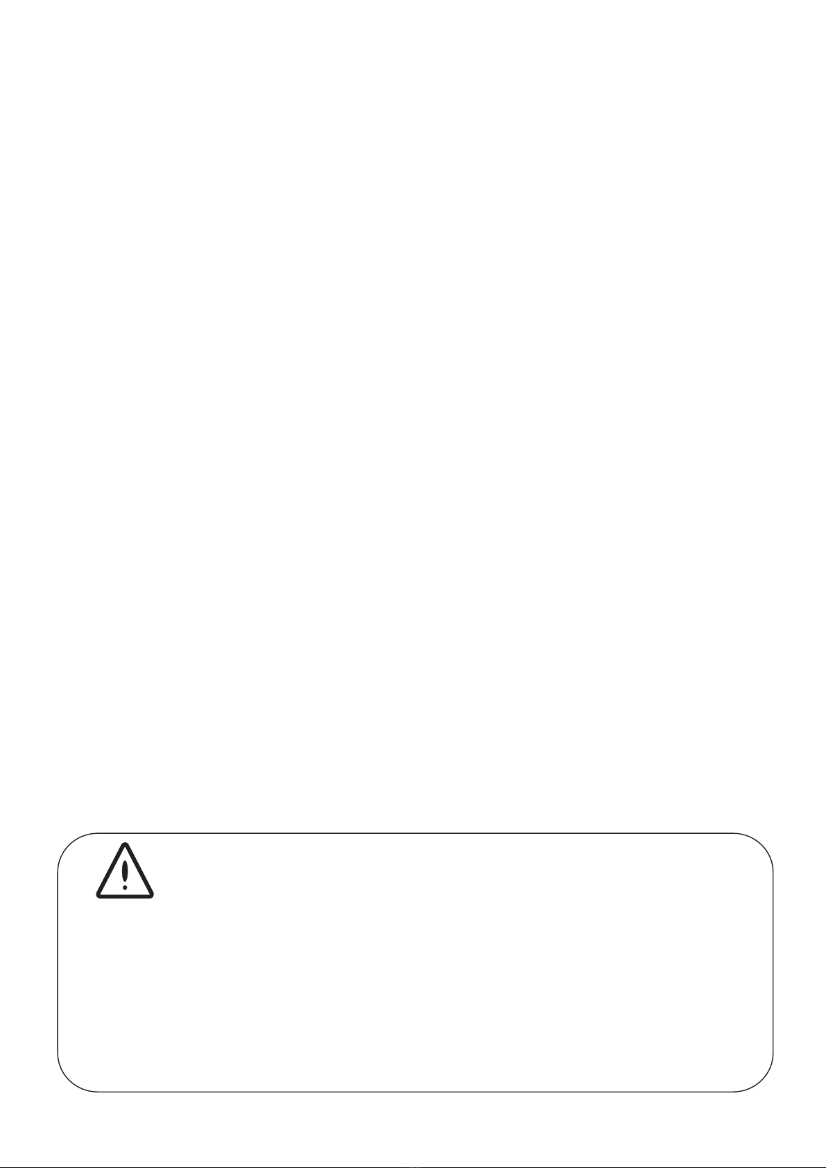
Motor
Cylinder
Block
Regulator

5
2.- CARRIAGE AND MAINTENANCE
The original packing is prepared so that carriage and storing of the product do
not cause any damage to the product, as long as this is done far from heat
sources and in dry, ventilated spaces.
Inside packing we include:
- DOSTEC-40 dosing pump
- Handbook 3
- Oil (250cm )
P: Polypropilene
C: Ceramic
I: AISI 304
F: PVDF
R: Racord 20mm
M: 1/2” BSP
N: 1/2 NPT
T: 3/4" BSP
S: 3/4" NPT
A: Three-phse
B: Single-phase 220V
C: Mono-phase 110V
D: 12V DC
E: 12V DC 400W
2: 2 cycles/s.
1: 1 cycle/s.
P0: Piston 50
P1: Piston 100
P2: Piston 200
P3: Piston 300
P5: Piston 500
D0: Diaphragm 50
D1: Diaphragm 100
D2: Diaphragm 200
D3: Diaphragm 300
REDUCTION FLOW MATERIAL CONNECTIONSMOTOR
60 - A 2 - P 0 P R
Code formulation

3.- TECHNICAL FEATURES
ELECTRIC CURRENT: As specified in the motor plate
POWER: 0.37 KW (0.5 Hp)
PROTECTION : IP-55
MATERIALS:
PISTON: P.E.U.A.P.M. / Ceramic
DIAPHRAGM: Elastomer base reinforced with fiber and P.T.F.E
clothing
SHAFT : P.E.T.P.
CYLINDER: P.P. / PVDF / AISI 304
VALVE(body): P.P / PVDF / AISI 304
VALVE(ball) : Body and borosilicate glass ball
RING GEAR : BRONCE .
PINION: F-154 CEM.
BLOCK: Alluminium cast
ECCENTRIC: F-154 CEM
RETENTION: FPM
NOISE LEVEL dB(A): minor than 70
WEIGH: 10 Kg (22 lb)
6
Piston
Diaphragm
CODE FLOW PRESSURE
l/h GPH bar PSI
60-A1-P0PR 25 7 15 217
60-A2-P0PR 50 13 15 217
60-A2-P1PR 100 26 15 217
60-A2-P2PR 200 53 11 160
60-A2-P3PR 300 79 7 100
60-A2-P4PT 500 132 4,5 65
60-A1-D0PR 25 7 15 217
60-A2-D0PR 50 13 15 217
60-A2-D1PR 100 26 10 145
60-A2-D2PR 200 53 8 116
60-A2-D3PR 300 79 5 72

7
in
mm
A
B
370
150
155
C
90
A
B
14,5
5,9
6,1
C
3,5
l/h A B C
50-300 12,6 6 7,6
500 12,6 6,9 8
DIMENSIONS
l/h A B C
50-300 320 154 195
500 320 175 205
l/h A B C
50-200 280 154 195
200 285 184 195
300 285 204 207
l/h A B C
50-200 11 6 7,6
200 11,2 7,2 7,6
300 11,2 8 8,1

8
Bars
65
4
3
2
1
L/H
7
200 -
180 -
160 -
200 l/h
L/H
10 Bars
987654321
80 -
100 -
90 -
100 l/h
432
1
L/H
5
300 -
270 -
240 -
300 l/h
Bars
1
10 Bars
8
6
4
2
L/H
22,5 45 -
20 40 -
25 50 -
12 14 15
25 - 50 l/h
DIAPHRAGME PUMP
FLOW - PRESSURE GRAPHICS

5.- INSTALLATION
GENERALITIES
To install this pump it is advisable to choose places protected from water,
away from heat sources and with air renewal.
Place the pump vertically over a totally rigid surface to achieve a proper
lubrication of all inner elements. Anticipate which will be the room you will
need to comfortably do the basic maintenance and install / desinstall the
pump.
9
4.- OPERATION
The electric motor (B) transmits its power by means of a reducer, made up of a
pinion (E) and a ring gear (F) solidary to an axis (I) and an eccentric (A) that
alternatively pushes and draws a shaft (C) threaded to the diaphragm (D).
The micrometic regulator (G) increases or diminishes the stroke of the shaft and the
diaphragm by means of a threaded pipe coupling (H), modifying the injection flow.
The dosing flow is adjustable from 0% tol 100%.
To regulate by means of an inverter is possible varying proportionaly the dosed flow
by the frequency supplied by an electric motor. The dosing flow is adjustable from a
10% to 100%.
B
E
FA
D
G
C
H
H

155mm
90mm
3,5 in
6,1 in
BLOCK
CEPSA SAE80W90
REPSOL EP 80W/90
SHELL SPIRLAXHD OIL 80W/90
ESSO GEAR OIL 80W/90
AGIP ROTRA MP
Pull out the oil cap for transport , fill the pump with the SAE oil 80W90 being
supplied (or similar oil), up to the level shown on the screen and put on the
working cap (black with a hole).
Approximate oil contents 3
250cm
Oils list:
80W-90
MOBILUDE HD 80W-90
BP ENERGEAR HT 80W-90
CATROL HYPOYC
GULF GEAR MP SAE 80W 90
ELF TRANSGEAR HD 80W-90
Min.
Max.
Fix the pump on the chosen flat surface by means of 4 screws.
ELECTRICAL CONNECTION
The electric protection of the motor must be installed and adjusted
following its nominal instensity (overloaded switch disjuntor). (See
wiring).
A disconnection dispositive must be installed in case of emergency.
The equipment must be protected to avoid untimely sudden starts.
10

11
ON
OFF
OFF
OVERLOAD PROTECTION
UVW
SINGLE PHASE CONNECTION
To work at 230 V single-phase at 50 Hz we will connect directly the motor wire to
the adequate protection. To work at 60 Hz we will connect the connection box
plates as shown in the drawing.
THREE-PHASE CONNECTION (50/60 Hz)
To work at 230 V we will plug the motor in triangle. Installing a protection.
To work at 400 V it will be a star connection. Installing a protection.
V1
W1
U1
230 V 400 V
V1
W1
U1
1,88 Amp 1,1 Amp
N
L
3 Amp.
230 VAC (50 Hz)
U1
W1
V1
U2
V2
W2
ON
OFF
OFF
OVERLOAD PROTECTION
L
N
HYDRAULIC CONNECTION
To evacuate leaks by the hole of the diaphragm breakage detector
in the inferior part of the cylinder we will take off the
security bolt dissassembling the cylinder and connecting a hose or
a pipe of a material compatible with the product to be dosed, and
collect the liquid in a safe place.
(R 1/2"),

12
SUCTION
It is essential to fit in the suction of the dosing liquid the filter of 100 mesh
supplied with the dosing pump.
Couple the suction pipe to the lower connecter of the cylinder, putting the mesh
filter in between. The stuff at the bottom of the tank must never be suctioned, to
avoid taking up undiluted particles.
The piping must be stiff enough so that it does not lose its shape when there is
suction.
To help suction the piping must be as short as posible, the pipe diameter must be
in keeping with that of the valve. For pipes of over 3 m, diameter must be
increased.
INJECTION
Fix the check valve supplied with the pump at the input of the water network, as
shown in the drawing, and couple the injection hose to the upper connecter of
the cylinder.
To protect the piping from the pressure variations or to achieve a continuous
flow, we suggest fitting a pulsation damper as near as possible to the pump.
In order to make priming easier, we suggest fitting a priming valve. You should
anticipate an adequate dispositive in order to collect the liquid than can get out
when priming, and derive it where it can not be harmful.
The pipe diameter will have to be the same as the valve diameter. For pipes over
15m length the diameter shall be increased. Do never insert a shutoff valve.
For the "Racor 20" connection use a hose with an inner diameter of 15 mm.
Install a safety valve in a derivation as near as possible from the
pump, in order to protect it and the whole installation from possible
over-pressures. This derivation must derive liquid to a safe place.

GENERAL INSTALLATION
2
3
4
91011
12
1
2
3
4
5
678
5
6
21
7
13
1. FILTER
2. VALVES
3. NON-RETURN VALVES
4. SUCTION
5. IMPULSION
6. SAFETY VALVE
7. SMALL DEPOSIT TO COLLECT LIQUID IN CASE OF BREAKOUT

14
6.- START UP AND REGULATION
STAND: Check that the pump is properly installed in its stand.
OIL: Take off re-filling lid and fill the pump with the provided oil: SAE
80 W 90 or equivalent. If the pump has several modules oil must be
spread to all fitting holes.
Lubricants list:
CEPSA SAE 80W 90
REPSOL EP 80W/90
SHELL SPIRLAX HD OIL 80W/90
ESSO GEAR OIL 80W/90
AGIP ROTRA MP 80W-90
MOBILUDE HD 80W-90
BP ENERGEAR HT 80W-90
CASTROL HYPOYC
GULF GEAR MP SAE 80W 90
ELF TRANSGEAR HD 80W-90
Check the oil level with the provided dipstick.
Approximate oil capacity: 100 cm3 per module.
When carrying, change filling lif for working lid.
CHECKING THE HYDRAULIC CIRCUIT: Check that all valves are
opened and that escapes from priming valves derive the liquid to a
proper receptacle.
ROTARY DIRECTION: Start up the pump to check that the rotary
direction coincides with the one shown by the arrow. To change rotary
direction invert two phases in the motor terminals box.
CHECKING OF PUMP: Check visually/auditorilly the proper working
of the pump.

1.- Prime the pump immersing the
suction pipe in a graduated
receptacle (A).
2.- Mark in the receptacle the liquid
level.
3.- Start up the pump and pour a
known volume (V) of measured
liquid in a second receptacle (B).
4.- Measure the time (t) that goes
between the start up of the pump
and the precise instant in which
the liquid reaches the level of the
mark of receptacle A.
5.- The dosed flows corresponds to:
Q(l/h) = V (liters) / t (seconds) x
3600
15
DOSING FLOW
Through the micrometic regulator ,we will adjust the dosing flow from 0 to 100%
depending on the wished value. It is not advisable a regulation under 10%.
In order to check the dosing flow:
A
B

60116 (2P)
60117 (1P)
62352(x4)
63213
63212
60111
60320(x4)
60319
60312
60313
60106
60303
60103
60120
60107
62129
64310
63420
63421
63422
63423
63424
62119
63332
62310
66333
63124
63125
60113
16
DOSTEC-40
Piston
62120-P/ F/ I
62121
62122
62123
63350
-P/ F/ I
-P/ F/ I
-P/ F/ I
62132 / 62143
62133 / 62144
60125 / 62145
60126 / 62146
60127
66-802
66-804-P/ F
63-809-P/ F
63-813-P
66-801
66-803-P/ F
63-808-P / F
63-812-P
28014
28021
60302(x4)
7.- MAINTENANCE

66171-P/ F
66226
66427
63814
66172-P/ F
66427
63814
66170-P/F
50 y 100 L/H 200 y 300 L/H
66171 66170
63814
66226
66172
63814
60110
60314
60108
60315
60318
66344
60109
62453
62451
60305
60104
61324
62453
62451
61305
60102
60300
63212(x4)
60115(2 P)
60114(1 P)
17
66226
66427
63814
Impulsion
63-809 -P/ F
50 - 300 L/H
66427
63814
Suction
63-808 -P/ F
Suction
66-803 -P/ F Suction
166-80
Impulsion
66-804 P/ F Impulsion
66-802
63806
63810
63807
63811
66334
60301
66172-P/ F

LIST OF PARTS DOSTEC-40 (Piston)
CODE DESCRIPTION UNITS
28014 MOTOR T71 B14 1/2HP THREE-PHASE 220V/380V 1
*28021 MOTOR T71 B14 1/2HP SINGLE-PHASE 220V -
60102 BLOCK LID DOSTEC 1
60103 POLE GUIDE 1
60104 AXIS WITH ECCENTRIC 1
60106 BRAKE 38 1
60107 SHAFT M20 DOSTEC 1
60108 DOSTEC REGULATION ROD 1
60109 REGULATOR DOSTEC 1
60110 REGULATOR BUMPER DOSTEC 1
60111 BUMPER BSF 1
60113 BLOCK DOSTEC 1
60114 RING GEAR 1 STROKE DOSTEC -
60115 RING GEAR 2 STROKE DOSTEC 1
60116 2 STROKE PINION DOSTEC 1
*60117 1 STROKE PINION DOSTEC -
60120 SPRING 38x65x4 1
60300 OIL PEEP HOLE 1
60301 REGULATOR PLUG 1
60302 SCREW M4x8 DIN933 I 4
60303 SCREW M6x6 DIN915 1
60305 WEDING PIECE 5x5x20 DIN6885-A 1
60312 O'RING 68x1,5 NBR 1
60313 O'RING 44X2 NBR 1
60314 O'RING 17x3 NBR 1
60315 O'RING 6,5x2 NBR 1
60318 GASKET M8 DIN125 1
60319 BEARING 608-2Z (8x22x7) 1
60320 ELASTIC GASKET DIN137-B(21x10.5x1) 4
61305 O'RING 88x2,5 NBR 1
61324 BEARING 6206 ZZ (30x62x16) 1
62119 CYLINDER SEPARATOR 1
62120-P/ F/ I CYLINDER 50L-S 1
*62121-P/ F/ I CYLINDER 100L-S -
*62122-P/ F/ I CYLINDER 200L-S -
*62123-P/ F/ I CYLINDER 300L-S -
*63350 CYLINDER 500L/H -
62129 BELLOW OIL 1
62132 PISTON 50L-S 1
62133 PISTON 100L-S -
60125 PISTON 200L-S M20 -
60126 PISTON 300L-S M20 -
60127 PISTON 500L M20 -
62143 PISTON 50L CERAMIC -
62144 PISTON 100L CERAMIC -
62145 PISTON 200L CERAMIC -
62146 PISTON 300L CERAMIC -
18

CODE DESCRIPTION UNITS
62310 O'RING 14x3 FPM 2
62352 SCREW M6x12 DIN 933 I 1
62451 BEARING 6202 ZZ (15x35x11) 2
62453 DIN 471 15 RETAINING RING 1
63124 FILLER PLUG C/RESP TCNS 3/8” 1
63125 DRAIN PLUG 3/8” 1
63212 ALLEN SCREW M5x12 DIN912 4
63213 GASKET 18x5x2,5 F5 1
*63331 ALLEN SCREW M8x20 DIN912 I -
63332 ALLEN SCREW M8x90 DIN 912 I 4
*63351 500L ELECTRO FLANGE 1
63420 SEAL 50L 2
*63421 SEAL 100L -
*63422 SEAL 200L -
*63423 SEAL 300L -
*63424 SEAL 500L -
64310 O'RING 55,5x3,5 2
66333 O'RING 14x3 NBR 2
66334 NUT M6 1
66344 GASKET M6 DIN125 1
VALVES
66-801 SUCTION VALVE P.P 1
66-803-P/F SUCTION VALVE O'RING -
62-801 SUCTION VALVE ½" INOX -
62-803 SUCTION VALVE ½" INOX NPT -
63-808-P/F SUCTION VALVE ½"-½" -
63-812-P SUCTION VALVE ½"-½" P.P NPT -
66-802 IMPULSION VALVE P.P 1
66-804-P/F IMPULSION VALVE TORICA -
62-802 IMPULSION VALVE ½" INOX -
62-804 IMPULSION VALVE ½" INOX NPT -
63-809-P/F IMPULSION VALVE ½"-½" -
63-813-P IMPULSION VALVE ½"-½" P.P NPT -
19

67.300 67115 (200l/h)
67119 (300l/h)
67114 (200l/h)
67118 (300l/h)
67116 (200l/h)
67123 (300l/h)
67301
67117 (200l/h)
67121 (300l/h)
67104 (50l/h)
67100 (50l/h)
67105 (50l/h)
62310
66333
85308(50l/h)
28014
28021
60116 (2P)
60117 (1P)
62352(x4)
63213
63212
60111
60320(x4)
60319
60312
60313
60106
60303
60103
60215
60122
62129
64310
DOSTEC-40
Diaphragm
63124
63125
60113
60302(x4)
Table of contents
Other ITE Water Pump manuals
Popular Water Pump manuals by other brands

Nimbus Water Systems
Nimbus Water Systems EU Patient manual

ARO
ARO SCD501BN08-V Series Operator's manual

ITT
ITT PumpSmart PS220 Configuration and operation manual

Pentair
Pentair IntelliFlo VF Installation and user guide

Ultranatura
Ultranatura SP-100 operating instructions

SKC
SKC 210-1000 Series operating instructions