9
4.ASSEMBLYAND INSTALLATION
Set the injection pump ECOFERTIC on the ground on a horizontal stand.
Put two inlets (A) and (B) in the water network where the pump is going to be
located at a minimum distance of 0.25 m. (0.75 ft) from each other.
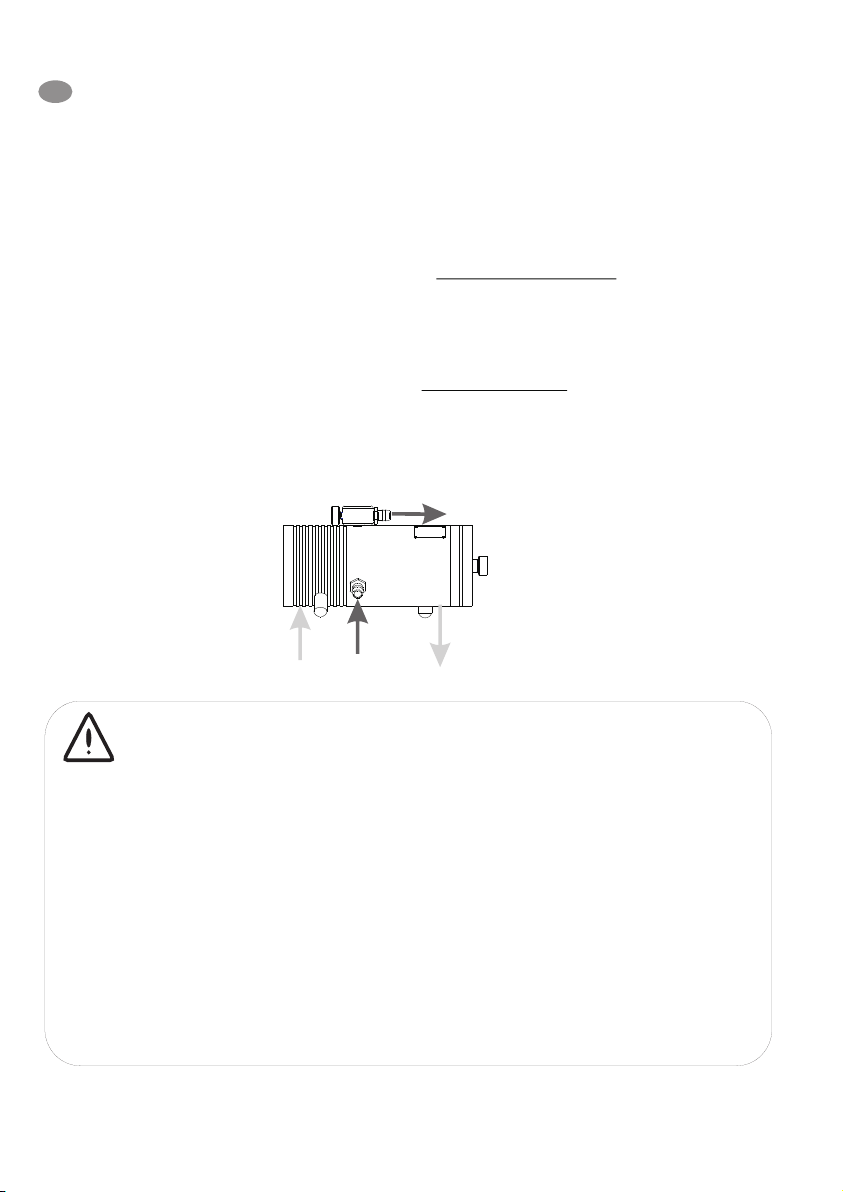
Pressure inlet (C) Connect the flexible pressure inlet hose (A) to the pump
connector (C) inserting a 120 mesh line filter.
Fertilizer injection (F) From the pump connector (F) put the flexible injection hose
at the irrigation network inlet (B).
Fertilizer suction (E) It is necessary to put a 120 mesh filter.
Drainage (D) Connect the free drainage hose to the outside or to the suction of the
irrigation pump.
IMPORTANT
It is advisable to put plastic ball valves at the water inlet (A) fertilizer injection (B)
and fertilizer suction (E) for the maintenance of the pump.
Fertilizer should not be sucked from de tank bottom to avoid taking up non dissolute
particles.
The ECOFERTIC pump keeps the injection liquid flow open even when it is stop,
which may produce a siphon effect. It is therefore suggested that, should it be
necessary, an antisiphon valve be set between the injection inlet (B) and the pump
connector (F) at 0.5 m. (1.5 ft) above the fertilizer tank.
RESET Should the pump not start the first time, the reset button should be pushed
down firmly.
8
GB
E
CD
F
4.MONTAJE E INSTALACIÓN
Colocar la bomba inyectora ECOFERTIC sobre una base horizontal en el suelo.
Hacer dos tomas en la red de agua donde se desee instalar la bomba (A) y (B)
distante entre ellas 0.25 m como mínimo.
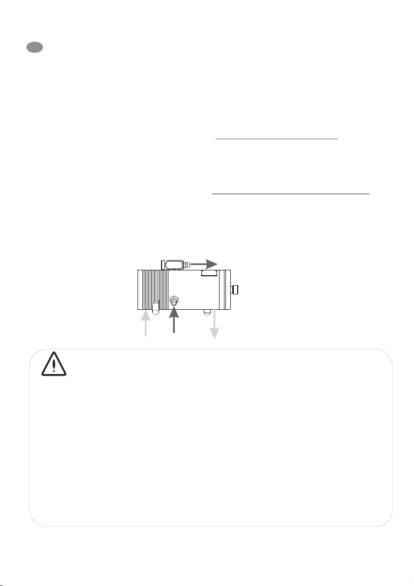
Toma de presion (C) Conectar la manguera flexible de toma de presión (A)en el
racor de la bomba (C) intercalando un filtro de linea de 120
mesh como mínimo.
Inyeccion del abono (F) Del racor de la bomba (F) colocar la manguera
flexible de inyección a la toma de la red de riego (B).
Aspiración del abono (E) Es necesario colocar un filtro de 120 mesh como
mínimo.
Desagüe (D) Conectar la manguera de desagüe libre al exterior o a la
aspiración de la bomba de riego.
IMPORTANTE
En la toma de agua (A), y aspiración de abono (E) se aconseja colocar válvulas de
bola de plástico para el mantenimiento de la bomba.
No aspirar el abono del fondo del depósito para evitar las partículas no disueltas.
La bomba ECOFERTIC mantiene el paso del líquido a inyectar abierto, aun
estando la misma parada, pudiendo ocurrir un efecto de sifón, por lo que se
recomienda, en caso de que sea necesario, colocar una válvula antisifón entre la
toma de inyección (B) y el racor de la bomba (F), situándola a 0.5 m. por encima de
los depósitos de abono.
REARME En caso de que la bomba no se pusiera en funcionamiento en su
primera puesta en marcha, accionar el rearme presionándolo hasta el
Fondo.
E
E
CD
F