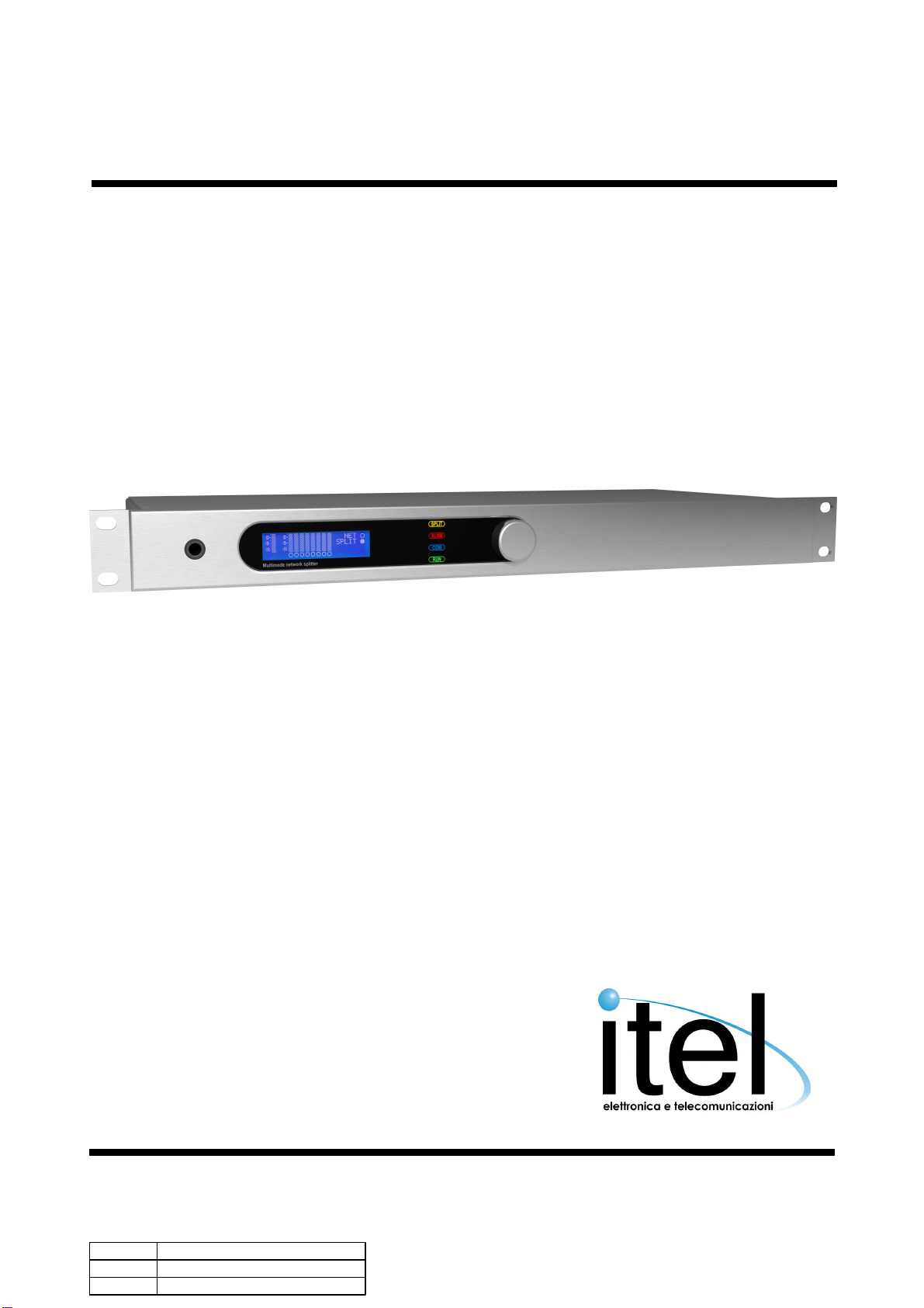
MPX-S Multimode network splitter2
© 2017 ITEL SNC
Table of contents
Section 1 Introduction 4
................................................................................................................................... 41 List of changes
................................................................................................................................... 52 Warnings
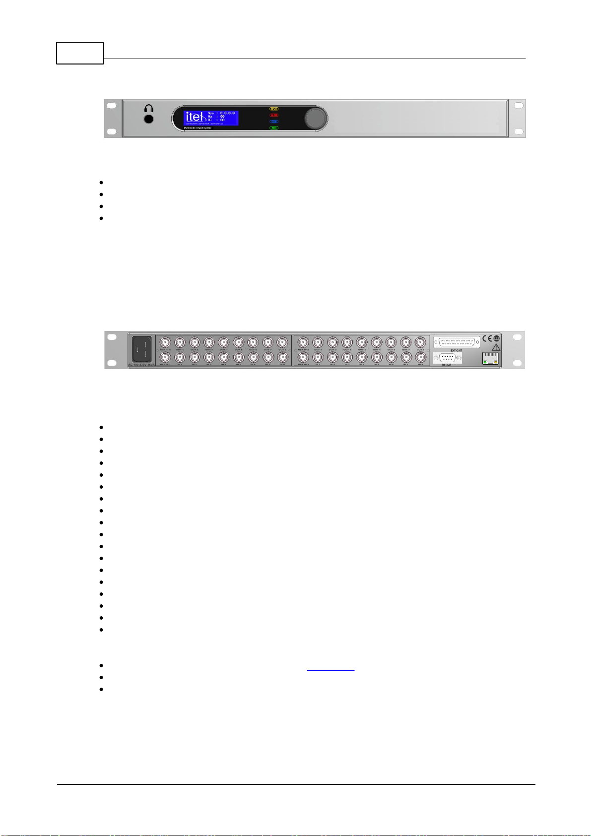
................................................................................................................................... 63 Front panel
................................................................................................................................... 64 Rear panel
................................................................................................................................... 75 EXT CNT connector
................................................................................................................................... 86 Editing and navigation
Section 2 Front panel display 11
................................................................................................................................... 111 Splitter status
......................................................................................................................................................... 11Input level
......................................................................................................................................................... 11Level monitor
................................................................................................................................... 112 RDS and MPX Audio monitor
......................................................................................................................................................... 12Mpx source selection and stereo levels
......................................................................................................................................................... 12RDS flags ......................................................................................................................................................... 12Radiotext ......................................................................................................................................................... 12RDS blocks percentage monitor
......................................................................................................................................................... 13AF tables ......................................................................................................................................................... 13RDS Stream monitor
......................................................................................................................................................... 13Subcarrier monitor and deemphasis selection
................................................................................................................................... 133 Alarms
................................................................................................................................... 144 System setup
......................................................................................................................................................... 14Display and Mpx inputs
......................................................................................................................................................... 14Interfaces and input modules
......................................................................................................................................................... 15Parallel status
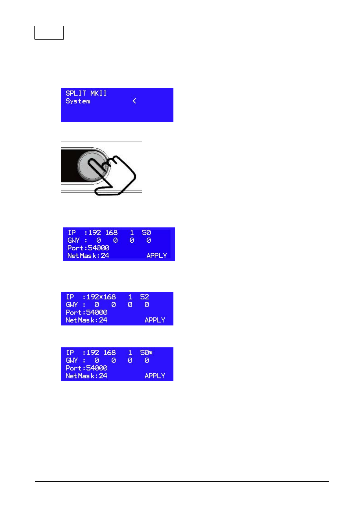
......................................................................................................................................................... 15Network setup
......................................................................................................................................................... 15System info
......................................................................................................................................................... 15System manteinance
................................................................................................................................... 165 HeadphonesLevel