Itho Daalderop HRU ECO 350 User manual

Itho Daalderop
HRU ECO 350
Installation manual

Original document.

3
ä
Warning!
Indicates a risk of personal injury to persons and/or serious
damage to the product, installation or surroundings.
ä Attention
!
Instruction relevant to the installation, operation, operation or
maintenance of the product. Ignoring this instruction may cause
minor bodily injury to persons and/or serious material damage
to the product, installation or environment.
Note
Instruction relevant to the installation, operation, operation or
maintenance of the product. Ignoring this instruction may cause
minor material damage to the product, installation or environment.
Foreword
This manual is intended for the installer of the ventilation system.
It contains important information about installation, use,
maintenance and malfunctions of the ventilation system.
The installer is responsible for the installation and commissioning
of the unit.
The following definitions are used in this manual to draw attention
to dangers, instructions or directions relating to persons, product,
installation and/or environment.
Although this manual has been compiled with the utmost
care, no rights can be derived from it.
Itho Daalderop reserves the right to change products and manuals
without prior notice.
Due to our continuous process of improving our products, this
document may differ from the product delivered to you. You can
download the latest version of this manual from our website.
Tip
Indications that may be relevant to the installation, operation,
operation or maintenance of the product, not related to injury to
persons or damage to property.
Tip
Don't forget to register the product via the website of Itho
Daalderop!

4
Content
1.
Safety and regulations 5
1.1.
Security 5
1.2.
Standards and guidelines 6
2.
Product information 7
2.1.
Versions 7
2.2.
Accessories 7
2.3.
Technical data 8
2.4.
Capacity chart 9
2.5.
Capacity 9
2.6.
Dimension drawings 10
2.7.
Spare parts 11
2.8.
Schemes 12
3.
Installation 15
3.1.
Installation requirements 15
3.2.
Installing the ventilation unit 15
3.3.
Connecting condensation drain 20
3.4.
Connecting the channels 21
3.5.
Dipswitch settings 22
3.6.
Connecting electrically 22
4.
Operation 23
4.1.
Ventilation modes 23
4.2.
Controls 23
4.3.
Sensors 24
4.4.
Signing in and out of wireless controls and 24
sensors
5.
Commissioning 25
5.1.
Preparation 25
5.2.
Commissioning 26
5.3.
Adjusting capacity 26
5.4.
Adjusting the supply/discharge balance 27
6.
Inspection and maintenance 28
6.1.
Inspection and maintenance schedule 28
6.2.
Inspection, cleaning/replacing filters 29
6.3.
Resetting dirt filter indication 30
6.4.
Cleaning mosquito filter 30
6.5.
Replace engine frost valve 30
6.6.
Inspection/Cleaning valves 31
6.7.
Inspect and clean fans 31
6.8.
Inspecting/cleaning channels 33
7.
Malfunctions 34
8.
Service parts 39
9.
Warranty 41
10.
Statements 42

5
1.
Safety and regulations
1.1.
Security
● Work on the ventilation system may only
be carried out by approved installers (1) in
accordance with the instructions in the
manual. Only accessories and parts as
prescribed by the manufacturer may be
used.
● Do not use the product for purposes
other than those for which it is intended,
as described in this manual.
● Handle electrical appliances with
care:
-
Never touch the device with wet
hands.
-
Never touch the device when you are
barefoot.
● This product and/or system may be
operated by children aged 8 years and
over and by persons with reduced
physical, sensory or mental capabilities or
lack of experience and knowledge if they
are supervised or instructed in its safe
use and are aware of the dangers of the
product and/or system.
● Cleaning and maintenance by the user
must not be carried out by children or by
persons with reduced physical, sensory or
mental capabilities or a lack of experience
and knowledge without supervision.
● Prevent children from playing with the
product and/or system.
● Do not use the product in the presence
of flammable or volatile substances such
as alcohol, insecticides, petrol, etc.
● Safety instructions must be followed to
prevent physical injury and/or damage to
the product.
● Maintenance and cleaning may only
be carried out after the appliance
has been de-energized.
● The product contains rotating parts.
Therefore, after disconnecting the
product from the power supply, wait at
least 10 seconds before opening or
touching the product, because these
parts will continue to rotate for some
time.
● Secure the system against
unintentional reactivation.
● Maintenance instructions must be
followed to prevent damage and
excessive wear and tear.
● The product must not be modified.
● The product is only suitable for a 230
V 50 Hz AC system.
● Make sure that the electrical system
to which the product is to be
connected meets the required
conditions.
● Do not expose the product to
weather conditions.
● Do not place any objects on the device.
● Regularly inspect the product for defects.
In the event of defects, switch off the
product and contact your installer or the
Itho Daalderop service department
immediately.
● Never switch off the product unless
when:
-
The product does not function properly.
-
You want to clean the product.

6
ä
Warning!
The specifications and settings of the appliance only comply
with the standards and laws of the country in which the
appliance is sold.
Applications outside this country can lead to very
dangerous situations!
-
Wants to carry out
maintenance on the
appliance.
-
The government advises closing
windows and doors in the event of a
calamity.
● Take care not to damage the electrical
circuit.
● Do not use the appliance to vacuum
water boilers, heating systems, etc.
● Make sure that the appliance drains into
a drain that is suitable and laid for this
purpose and that drains to the outside.
● Keep valves and grids free and clean.
1) A certified installer is an installer working for a central heating or
mechanical installation company registered with the Chamber of
Commerce and included in the SEI recognition register (Stichting
Erkenning Installatiebedrijven) or who has a Sterkin recognition.
1.2.
Standards and guidelines
The installer must ensure that the entire installation complies with
the legal requirements, the regulations contained in this document
and other applicable documentation from the manufacturer.
All legal requirements and regulations are subject to additions,
amendments or legal requirements that came into force later apply
at the time of installation.
After installation, there must no longer be any health, safety or
environmental risks in accordance with the applicable CE
directives. This also applies to other products included in the
installation.

7
Versions HRU ECO 350
2.
Product information
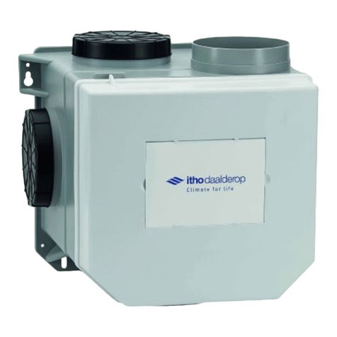
The HRU ECO 350 consists of a central balance ventilation unit
with heat recovery, a mounting set and a condensate drain
connection.
2.1.
Versions
2.2.
Accessories
Article
Type
Description
03-00389
HRU ECO 350
LR
Balance ventilation unit with
Heat recovery; RF; low buildings
application; earthed plug
03-00390
HRU ECO 350
LP
Balance ventilation unit with
Heat recovery; RF; low buildings
Application; Perilex plug
03-00391
HRU ECO 350
HR
Balance ventilation unit with
heat recovery; RF; high-rise buildings
application; earthed plug
03-00392
HRU ECO 350
HP
Balance ventilation unit with
heat recovery; RF; high-rise buildings
Application; Perilex plug
Article no.
Type
Description
536-0124
RFT W
Wireless control switch with
Three modes and timer function
(White)
536-0150
RFT CAR
Wireless RF control switch
with 2 modes, auto and timer
function.
580-0230
HRS-3I C
Wired 3-position switch for
installation
04-00045
RFT-CO2 230V
RFT-CO2 sensor with control - 230
V fed
04-00046
RFT-RV BAT
RFT-RV sensor with control -
battery-powered
545-7550
RF-PIR BAT
RF-PIR presence sensor -
battery-powered
03-00062
Spider Base
Climate thermostat
545-1507
VKK
Ventilation Boiler Coupling
545-1508
VKK-HB
Ventilation Boiler Coupling HB
591-1070
FGD 180-50
Sound-absorbing flexible hose, Ø
180 mm, length 50 cm
591-1270
FGD 180-100
Sound-absorbing flexible hose, Ø
180 mm, length 100 cm
591-1050
FGD 152-50
Sound-absorbing flexible hose, Ø
152 mm, length 50 cm
591-1250
FGD 152-100
Sound-absorbing flexible hose, Ø
152 mm, length 100 cm
04-00089
OPTIMA 2 SET
Optima 2 set (2x CO2+ RFT AUTO)
63-00004
OJ 600I
PureBlue Induct 600
air purifier

8
ä
Warning!
Never connect the appliance with an extension cord!
2.3.
Technical data
Description
Symbol
Unit
HRU ECO 350
LR / HR
LP / HP
DIMENSIONS AND WEIGHT
Dimensions (HxWxD)
—
mm
848 x 730 x 479
Weight
—
kg
24
CONNECTIONS
Channel connections top side
—
mm
4x Ø 150 internal/Ø 180 external
Duct connection underneath
—
mm
2x Ø 150 internal/Ø 180 external
(to/from home)
Drainage of condensation
—
mm
Ø 40 mm external
GENERAL
IP classification
—
—
IP21
Safety class
Double insulated
Installation class
II
Filter class
—
—
Standard G3
RF (integrated)
—
—
30 m free field, 868 MHz
Supply voltage
—
—
~ 230V - 50Hz (+/- 10%)
Power connection
—
—
3-core
mains cable
with protective
earth
plug
5-core
power
cable
with
Perilex-
plug
TECHNICAL PARAMETERS
Thermal efficiency of heat recovery
ƞt
%
94
Electrical input power of the fan drive,
at maximum flow rate
—
W
145

9
2.4.
Capacity chart
2.5.
Capacity
Line
graph
Capacity
Q
[m3/h]
Pressu
re dP
[Pa]
Power
P
[W]
Sound power
radiated (LwA)
dBA
Sound power level
Dissipation (LwA)
dBA
Position 1
Minimum
A-a
50
14
7,5
30
42
Position 1
Standard
50
14
7,5
30
42
Position 1
Maximum
B-b
100
205
42
49
60
Position 2
Minimum
100
26
12
41
53
Position 2
Maximum
C-c
150
115
39
49
57
Position 3
Minimum
D-d
250
43
57
52
59
Position 3
Standard
250
139
90
56
62
Position 3
Maximum*
E-e
350
100
146
60
65
* Indicated in graph with dotted line
500 Pa E
Power lines140 W
c
100 Pa B
a
dP [Pa]
P [W]

10
ithodaalderup
1
M
N
--+--- 480 - - 125
00
ij
306 424
2.6.
Dimension drawings

11
10 4
5 11 6
2.7.
Spare parts
Legend
1
Ventilation unit
2
Bayonet rear side
3
Heat exchanger
4
Front panel
5
Front door
6
Filter
7
Engine module
8
Connection cap with control board and power cable
9
Mosquito filter
10
Frost valve
11
Bypass valve

12
Note
Despite the heat exchange, in which the fresh outside air is pre-
heated, the balanced ventilation system should not be regarded
as a heating system. It is a ventilation system that contributes to
a comfortable and healthy living environment in the home.
2.8.
Schemes
The HRU ECO 350 has as standard a 3-position control where the
ventilation flow in the low position and the high position can be
infinitely adjusted by means of potentiometers on the unit. In
addition, the ventilation unit has a number of automatic controls that
operate continuously in the background.
2.8.1.
Heat recovery
Before the polluted air is removed to the outside, it is filtered and
passed through the heat exchanger. The fresh outside air is also
filtered and passed through the heat exchanger before it is brought
into the house. In the supply air, so that this energy is not lost.
Heat recovery takes place with a very high efficiency.
2.8.2.
Summer bypass scheme
The purpose of the summer bypass control is to ventilate the house
with less, or completely without, heat transfer.
The Itho Daalderop heat recovery unit HRU ECO 350 is supplied
as standard with a bypass valve that is 100% integrated in the
unit. This valve works fully automatic. The bypass ensures that
the sucked in outside air is guided around the exchanger. The
return air still passes through the exchanger.
This automatic control will be activated mainly at night, in summer.
The outside air is then usually cooler than the warm inside air.
2.8.3.
Vorstregeling
The purpose of the frost control is to prevent the heat exchanger
from freezing and to prevent ventilation.
If the temperature of the supply air in the heat exchanger gets too
close to freezing point, the unit will regularly open the frost flap at
the top of the unit and draw in warm room air. This warm room air
is mixed with the drawn in cold outside air. At the same time, the
supply fan starts to turn harder (the fan is speeded up so that the
amount of fresh outside air remains the same). Because the fresh
cold outside air is pre-heated, the warm extracted air from the
house does not have to heat the cold freezing air as much. The
automatic control keeps the temperature of the supply air in the
heat exchanger safely above freezing point.
Should the outside temperature drop even further, the supply fan
will turn softer (the fan will be turned down to a minimum).
If the temperature continues to drop, the drain fan will increase and
the supply fan will continue to run at a minimum.
If the outside temperature becomes extremely low, the supply fan
will be switched off, but the exhaust fan will continue to operate.
The frost valve will therefore be closed.
After a certain period of time, the supply fan will start to run at a
minimum and the frost valve will be opened again to check whether
the frost hazard is now gone.
If the outside temperature rises, the above measures are carried
out in reverse order until the danger of frost has passed. The
resident 'always' determines the discharge air quantity.
Note
The summer bypass control is not cooling, but it does ensure
that the house remains cool longer in the summer night.

13
CHP AWW
ON ON
Note
It is advisable to check the LED on the ventilation unit regularly.
ä Attention
!
If a dirty filter is detected, the resident also receives a signal
because the operation suddenly seems to work the other way
around: if you press the Low mode button on the remote control,
the ventilation unit goes to High mode and if you press High
mode, the unit goes to Low mode. Check the LED on the
ventilation unit. If it flashes, the filter needs to be cleaned or
replaced.
2.8.4.
Filters
The HRU ECO 350 has two filters, one for each air flow. Both
filters are placed in the ventilation unit in such a way that they
protect the exchanger from contamination. In addition, the filter in
the air supply also protects the user against dust and other
contaminants in the sucked in outside air.
There are different types of filters:
● Filter G3 (Filter ISO Coarse ³45%).
This filter is supplied as standard with the appliance and is very
suitable as a 'building material filter' in the first period after
delivery of the new home. After about three months the filter has
to be replaced by a G4 or F7 filter.
● Filter G4 (Filter ISO Coarse ISO 65%.).
This coarse filter is mainly used to filter relatively large dust
particles from the air. This mainly protects the heat
exchanger against penetrating dirt.
● Filter F7 (Filter ISO ePM2.5 70%).
In addition to the coarser dust particles, this fine filter also
stops finer dust particles (pollen). Especially people with
allergy complaints, who are sensitive to this, can benefit
from this.
Over time, the filters will become dirty, which will reduce the
capacity of the ventilation unit. It is therefore necessary that the
filters are cleaned according to the instructions and eventually
replaced.
2.8.4.1.
Filter warning
The control of the ventilation unit keeps track of when the filters
need to be cleaned or replaced by means of a counter. If a dirty
filter is detected, the LED (4) on the ventilation unit flashes orange.
1
Balance supply setting
2
Potmeter-High setting
3
Potmeter-Low setting
4
Status LED / Dirt filter indication
5
Communication connection
6
Dipswitch setting (VKK & AWW)
Legend
ä
Warning!
The HRU ECO 350 must be fitted with the appropriate filters at all
times! Without filters, the unit can suffer irreparable damage.

14
2.8.4.2.
Filter warning CO2 sensor or RH
sensor
If the ventilation unit detects that the filter needs to be cleaned or
replaced, the unit sends a message to the controllable CO2 sensor,
and RH sensor (if connected). The status LED on the sensor then
flashes orange at 1 Hz. After cleaning or changing the filter, reset
the counter, see Resetting the Dirty Filter Indication on page 30.
2.8.4.3.
Filter warning Spider
climate thermostat
If the ventilation unit detects that the filter needs to be cleaned or
replaced, the unit sends a message to the Spider air conditioning
thermostat (if connected). The display of the climate thermostat will
show the message Replace filter. The orange filter symbol flashes
and the ventilation symbol and the Service button illuminate
continuously. After cleaning or changing the filter, the counter must
be reset, see Resetting the dirt filter indicator on page 30.
2.8.4.4.
Status LED
The appliance is equipped with a status LED. The status LED can
display the following messages:
Pattern
Function
Green
Orange
Flashes 1x/s
Flashes 1x/s
Identification
Flashes 1x/s
Login mode
Burns 6 s
Flashes 1x/s
Frost mode
Burns 5 s
Flashing 2x/s
Bypass mode
Brandt
Normal operation
Pattern
Function
Red
Orange
Flashes 1x/s
Flashes 1x/s
Error drain fan
Flashes 1x/s
Flashing 2x/s
Error
supply fan
Flashing 2x/s
Flashing 2x/s
Sensor error
outlet temperature
Flashing 2x/s
Flashing 3x/s
Sensor error
supply temperature
Flashing 3x/s
Flashes 1x/s
Sensor error
Flashes 1x/s
Filter dirt
2.8.5.
Ventilation Coupling VKK
With the coupling type VKK and VKK-HB it is possible to
connect the HRU ECO 350 to the Remeha HR combi boiler the
Avanta. The purpose of the coupler is to simplify the ducting
system between the HRU ECO 350 and the boiler. Both the
ventilation installation and the boiler need a supply and an
exhaust duct to and from the outside. The VKK coupler
combines the outlet of the ventilation installation with the supply
and outlet of the boiler (2 duct system).
For example, only a supply and exhaust duct is required
for the ventilation system (up to 12 floors).
The coupling type VKK-HB (up to 40 storeys) combines the air
outlet of the ventilation system with the air supply of the boiler. Both
have a separate exhaust system (3-channel system).
VKK coupler-HB
VKK coupler
See above: Dipswitch settings on page 22.
ä Attention
!
If a VKK or VKK-HB coupling is installed, this must be set on
the ventilation unit!

15
3.
Installation
3.1.
Installation requirements
Please take the following into account before installing the
system:
● Mount the ventilation unit
-
in a closed set-up room (where the system can
cause as little noise nuisance as possible).
-
in an installation room that is frost-free.
-
in the vicinity of a socket outlet 230 V, 50 Hz (for Euro
plug or Perilex plug, depending on the type); the length of
the power cable is 1.5 m.
-
in the vicinity of a siphon with connection to the
sewerage system (for connection of the condensation
drain).
-
in such a way that it remains accessible for service and
maintenance.
-
on a wall with sufficient load-bearing capacity (min. 200
kg/m2).
● The duct system and the drainage and supply points must
be correctly dimensioned.
● The correct fastening materials must be present.
3.2.
Installing the ventilation unit
3.2.1.
Unpacking and checking
a)
Carefully take the equipment out of the box.
b)
Check the nameplate details and type for correctness as shown
on the sticker on the outside of the box.
c)
Check the equipment for damage and completeness.
d)
Check that the ventilation unit comes with a manual
(installation and/or user manual) and the necessary
accessories (e.g. condensation drain connection and assembly
kit).
e)
Place the ventilation unit upright on the ground.
3.2.2.
Mounting positions
The ventilation unit is mounted on the wall.
Depending on the arrangement of the ducts, the ventilation unit
can be mounted to the wall 'standard' (as supplied in the
packaging) or 'rotated' (see Conversions for mirrored mounting
on page 17).
The pictograms on the side of the duct connections indicate
where the ducts of the house are to be connected.
ä Attention
!
To prevent condensation, the duct coming from outside and the
duct going out to the ventilation unit must be insulated thermally
and vapour-tight.
ä Attention
!
Always ensure that the ventilation unit is mounted in such a
way that the ducts are connected to the correct inlet and outlet
openings!
Tip
When positioning the ventilation unit, take into account that
sufficient space is also kept free to provide service. This
requires at least 500 mm extra space at the front of the
ventilation unit.
Tip
To prevent noise complaints, Itho Daalderop recommends
connecting the two ducts coming from the house with silencers.
ä Attention
!
Attach the ventilation unit to a concrete surface, not to a wooden
or plaster surface or to a surface with insufficient load-bearing
capacity (˂ 200 kg/m2). This leads to noise nuisance.

16
Mounting
positions
High rise 'standard
High-rise 'twisted' (1)
C
A
BD
D
E
B
D
CA
DE
Low-rise 'standard
Low-rise 'twisted' (1)
C
A
ED
D
B
E
D
CA
DB
1) See Conversion for assembly.
Legend
A Exhaust air to the outside
C
Supply air from outside
B Supply air to dwelling
D
Exhaust air from home
E
Close

17
3.2.3.
Conversion for mirrored mounting
The HRU ECO 350 comes standard with the motor module on the
left side. If it is more convenient for the duct system, the ventilation
unit can be 'mirrored' easily and without tools before being
mounted on the wall. If it is not necessary to rotate the unit, this
section can be skipped.
(a) Remove both filter holders.
c)
Also turn the bayonet at the back one quarter turn
counterclockwise and remove the bayonet.
d)
Move the front panel upright (without turning it) to the other
side and place the front panel by pressing the rim under the
black rim of the enclosure.
This is easiest if the ventilation unit lies flat on the ground.
b) Turn the front door with bayonet lock one quarter turn anti-
clockwise and remove the front door.

18
e) Place the front door on the new front as shown. Turn the front
door a quarter turn clockwise until it is neatly vertical.
Make sure that the round disc of foam, in the hole against the
changer between the door and the changer, is present.
(g) Fit both filter holders.
The ventilation unit is now 'mirrored' and ready for
further assembly.
f) Place on the bayonet at the new rear as shown. Turn the bayonet
a quarter turn clockwise until the bayonet is secure.
Make sure that the foam disc is between the changer and the
bayonet.

19
30
30
300
480
30
480
3.2.4.
Wall mounting
a)
Determine the exact location of the unit, taking into account
the Installation requirements on page 15.
b)
Fix the wall plate level on the wall using 5 screws (mounting
material not supplied).
Standard assembly.
Turned assembly.
The edge of the mounting kit corresponds to the centre line of the
ducts. The notch at the bottom of the mounting kit indicates the location
of the condensation drain (left for a standard unit and right for a turned
unit).
c)
Hang the ventilation unit with the mounting strip on the wall
plate. The mounting bracket is already placed in the unit. Make
sure that the ventilation unit rests on the supports on the
underside of the wall plate.
The sides of the wall plate correspond to the centre lines of the duct
connections.
80
600
848
168
80
600
848
168

20
ä Attention
!
If the ventilation unit is placed outside the thermal shell of the
dwelling (for example in an uninsulated attic), the condensation
drain must be thermally insulated up to the ventilation unit.
ä Attention
!
A suitable siphon (horizontal or vertical) must be installed to
connect the condensate hose to the condensate drain. For a
vertical siphon, the unit must be raised sufficiently with beams.
ä
Warning!
Make sure at all times that the condensation hose sticks into
the siphon (at least 30 mm under water) up to EXPLOSURE.
Otherwise you will get leaks!
3.3.
Connecting condensation drain
In winter, the exhaust air from the house can condense in the heat
exchanger. A condensation drain is integrated in the ventilation
unit for this purpose.
d)
Fill the siphon to get a water trap.
a)
Mount the condensate drain connection (not supplied) on the
condensate drain outlet of the ventilation unit.
b)
Connect a condensation hose (minimum Ø20 mm inside) to the
condensation drain connection.
c)
Feed the condensation hose to a siphon capable of creating
at least 50 mm of water trap. Insert the hose deep enough
into the siphon.
ä Attention
!
Make sure that the condensation hose is mounted from top to
bottom to the drain.
30 mm
> 50 mm
ä
Warning!
Always mount the appliance on a wall, never standing on the
floor!
ä Attention
!
The condensation hose must not have any sharp bends!
Table of contents
Other Itho Daalderop Fan manuals
Popular Fan manuals by other brands

Davies Craig
Davies Craig 10" Thermatic Fan installation instructions

Humongous Fan
Humongous Fan 51512 installation guide

Monte Carlo Fan Company
Monte Carlo Fan Company 5DIC52 D Series Owner's guide and installation manual

Parrot Uncle
Parrot Uncle F6111110V Installation & operating instructions

Vents
Vents TT Silent-M Series user manual

NuAire
NuAire AVT1-R installation manual