Itho Daalderop CVE-S ECO Quick start guide

Installation & use
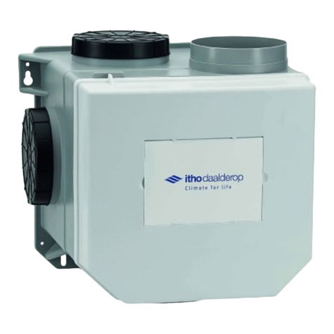
Itho Daalderop
CVE-S ECO
D

Original document.

3
ä
Warning!
Indicates a risk of personal injury to persons and/or
serious damage to the product, installation or
surroundings.
Foreword
This manual is intended for the userand approved
installer of the product and contains important information
on installation, use, maintenance and malfunctions.
The installer is responsible for the installation and
commissioning of the unit.
The following definitions are used in this manual to
draw attention to dangers, instructions or directions
relating to persons, product, installation and/or
environment.
Note
Instruction relevant to the installation, operation,
operation or maintenance of the product. Ignoring this
instruction may cause minor material damage to the
product, installation or environment.
ä Attention
!
Instruction relevant to the installation, operation,
operation or maintenance of the product. Ignoring
this instruction may cause minor bodily injury to
persons and/or serious material damage to the
product, installation or environment.

4
Tip
Don't forget to register the product via the website of
Itho Daalderop!
Although this manual has been compiled with the
utmost care, no rights can be derived from it.
Itho Daalderop reserves the right to change
products and manuals without prior notice.
Due to our continuous process of improving our products,
this document may differ from the product delivered to you.
You can download the latest version of this manual from our
website.
Tip
Indications that may be relevant to the installation,
operation, operation or maintenance of the product,
not related to injury to persons or damage to
property.

5
Content
1.
Safety and regulations 6
1.1.
Security 6
1.2.
Standards and guidelines 10
2.
Product information 11
2.1.
Product description 11
2.2.
Versions EN 13
2.3.
Accessories 13
2.4.
Technical Specifications 14
2.5.
Capacity 15
2.6.
Product card information 16
2.7.
Improve energy label 18
2.8.
Recycle 18
3.
Installation 19
3.1.
Installing the ventilation unit 19
3.2.
Connecting electrically 20
4.
Operation 22
4.1.
Subscribe and unsubscribe RF controls 25
4.2.
Subscribe and unsubscribe Spider Base 25
5.
Commissioning 26
5.1.
Adjusting capacity 28
6.
Inspection & Maintenance 30
6.1.
Inspection 30
6.2.
Maintenance 32
7.
Service parts 36
8.
Malfunctions 38
9.
Warranty 45
10.
Statements 46

6
1.
Safety and regulations
1.1.
Security
●Work on the ventilation
system may only be carried
out by approved installers (1) in
accordance with the
instructions in the manual.
Only accessories and parts
as prescribed by the
manufacturer may be used.
●Do not use the product for
purposes other than those
for which it is intended, as
described in this manual.
●Handle electrical
appliances with care:
-
Never touch the device with
wet hands.
-
Never touch the device
when you are barefoot.

7
●This product and/or system
may be operated by children
aged 8 years and over and by
persons with reduced
physical, sensory or mental
capabilities or lack of
experience and knowledge if
they are supervised or
instructed in its safe use and
are aware of the dangers of
the product and/or system.
●Cleaning and maintenance by
the user must not be carried
out by children or by persons
with reduced physical,
sensory or mental capabilities
or a lack of experience and
knowledge without
supervision.
●Prevent children from playing
with the product and/or
system.
●Do not use the product in the
presence of flammable or
volatile substances such as
alcohol, insecticides, petrol,
etc.

8
●Safety instructions must be
followed to prevent physical
injury and/or damage to the
product.
●Maintenance and cleaning
may only be carried out after
the appliance has been de-
energized.
●The product contains rotating
parts. Therefore, after
disconnecting the product
from the power supply, wait at
least 10 seconds before
opening or touching the
product, as these parts will
continue to rotate for some
time.
●Secure the system against
unintentional reactivation.
●Maintenance instructions must
be followed to prevent damage
and excessive wear and tear.
●The product must not be
modified.
●The product is only suitable
for a 230 V 50 Hz AC
system.
●Make sure that the electrical
system to which the product
is to be connected meets the
required conditions.

9
●Do not expose the product to
weather conditions.
●Do not place any objects
on the device.
●Regularly inspect the product
for defects. In the event of
defects, switch off the product
and contact your installer or
the Itho Daalderop service
department immediately.
●Switch the product off
when:
-
The product does not
function properly.
-
You want to clean the
outside of the product.
●
Take care not to damage
the electrical circuit.
●Do not use the appliance to
vacuum water boilers, heating
systems, etc.
●Make sure that the appliance
drains into a drain thatis
suitable and laid for this
purpose and that drains to the
outside.
●Keep valves and grids free
and clean.
1)
A qualified installer is an installer working for a central heating or
mechanical installation company registered with the Chamber
of Commerce and included in the SEI recognition register
(Stichting Erkenning Installatiebedrijven) orwho has a Sterkin
recognition.

10
ä
Warning!
The specifications and settings of the appliance only
comply with the standards and laws of the country in
which the appliance is sold.
Applications outside this country can lead to very
dangerous situations!
1.2.
Standards and guidelines
The installer must ensure that the entire installation
complies with the legal requirements, the regulations
contained in this document and other applicable
documentation from the manufacturer.
All legal requirements and regulations are subject to
additions, amendments or legal requirements that came into
force later apply at the time of installation.
After installation, there must no longer be any health,
safety or environmental risks in accordance with the
applicable CE directives. This also applies to other
products included in the installation.

11
2.
Product information
2.1.
Product description
Living comfort and energy savings are becoming
increasingly important in housing construction.
Nowadays, homes are becoming increasingly better
insulated. Unfortunately, good insulation often comes at
the expense of the indoor climate. Without good
ventilation, moisture, moulds and dust mites can escape
and the air in the house can quickly feel 'stuffy' due to an
increasing concentration of CO2 (carbon dioxide). Itho
Daalderop develops equipment that regulates the indoor
climate and takes into account the requirements for
comfort and energy consumption in homes.
One of these devices is the Itho Daalderop ventilation
unit CVE-S ECO.
The CVE-S ECO ventilation unit is used in individually
controllable ventilation systems based on decentralised,
natural air supply in the facade and central, mechanical
air extraction in the wet rooms.
The CVE-S ECO ventilates several rooms in the house.
Through channels, the kitchen, bathroom, toilet and, if
necessary, the storage/storage room can be accessed.
laundry room connected to the unit for air extraction. A
motorless extractor hood can be part of the system.
To ensure good air distribution, extraction valves are
fitted to the openings of the ventilation ducts in the rooms
to be ventilated. Air is extracted via these extraction
points, while fresh air flows in from outside to inside via
air supply openings (e.g. grilles) in the façades of living
rooms and bedrooms.
The CVE-S ECO is now also equipped with a built-in
humidity sensor as standard. Thanks to its smart control,
this humidity sensor accurately measures the air humidity
and automatically adjusts the ventilation accordingly.
When the sensor detects an (abrupt) rise, the automatic
control will speed up the ventilation unit to the maximum
position. The RH sensor cannot be adjusted (without
special Itho Daalderop tools).
In this way, the unit helps to reduce the humidity in your
bathroom, refresh the toilet and eliminate cooking odours
from the kitchen.

12

13
2.2.
Versions EN
Article
Type
Description
03-00398
CVE-S ECO SE
Ventilation unit standard, Int. Stainless steel sensor, euro plug
03-00400
CVE-S ECO SP
Ventilation unit standard, Int. Stainless steel sensor, Perilex plug
03-00402
CVE-S ECO HE
Ventilation unit high performance, geïnt. RH sensor, euro plug
03-00403
CVE-S ECO HP
Ventilation unit high performance, geïnt. Stainless steel sensor, Perilex plug
03-00404
CVE-S PAK
Everything in 1 vent. package, CVE S, geïnt. RV sensor and RFT-AUTO control
03-00405
CVE-S PAK SPI
Everything in 1 vent. package, CVE S, geïnt. RV Sensor and Spider Base
2.3. Accessories
Article
Type
Description
03-00062
Spider Base
Climate thermostat
04-00045
RFT-CO2 230V
RFT-CO2 sensor with actuator - 230 V power supply
04-00046
RF-RV BAT
RFT-RV sensor with control - battery operated
04-00048
CO2 CONSTRUCTION
CO2 sensor for CVE installation
545-7550
RF-PIR BAT
RF-PIR presence sensor - battery-powered
536-0150
RFT CAR
Wireless control switch with two positions, one automatic position and a
timer function.
580-0230
HRS-3I C
Wired 3-position flush-mounted switch
580-0245
HRS O C
Surface mounted box for wired 3-position switch HRS-3
540-7960
CVH 125
Mechanical non-return valve diameter Ø 125 mm
591-1030
FGD 128-50
Sound-absorbing flexible hose, Ø 128 mm, length 50 cm
591-1230
FGD 128-100
Sound-absorbing flexible hose, Ø 128 mm, length 100 cm

14
2.4.
Technical Specifications
Description
Symbol
Unit
CVE-S ECO
SE
HE
SP
HP
DIMENSIONS AND WEIGHT
Dimensions (HxWxD)
—
mm
350 x 355 x 294
Weight
—
kg
3,4
CONNECTIONS
Connections from home
—
mm
4x Ø 124
Connection to the outside
—
mm
1x Ø 124
GENERAL
IP classification
—
—
IP31
RF (integrated)
—
—
30 m free field, 868 MHz
Supply voltage
—
—
~ 230V - 50Hz
Power connection
—
—
2-core power
cable with Euro
plug
5-core
power
cable
with
Perilex-
plug
TECHNICAL PARAMETERS
Maximum power consumption
P
W
50
62
50
62

15
2.5.
Capacity
Type S
Capacity (m3/h)
Pressure (Pa)
Power (W)
Setting 1 minimum
25
5
1,6
Stand 1 standard
75
11
2,5
Setting 1 maximum
125
31
5,2
Position 2 standard (*)
150
44
7,3
Setting 3 minimum
175
60
10,2
Stand 3 standard
225
100
18,7
Setting 3 maximum
375
100
50
Type H
Capacity (m3/h)
Pressure (Pa)
Power (W)
Setting 1 minimum
25
5
1,6
Stand 1 standard
75
11
2,5
Setting 1 maximum
125
31
5,2
Position 2 standard (*)
175
60
10,2
Setting 3 minimum
175
60
10,2
Stand 3 standard
275
100
31,6
Setting 3 maximum
415
100
62
*) Position 2 is the automatic position when sensors (CO2, RH and/or PIR) are logged in. The capacity is automatically controlled
between low and high.

16
2.6.
Product card information
Itho Daalderop
CVE-S ECO
Description
Symbol
Unit
S
H
Specific energy consumption class
—
—
D
Specific energy consumption, under moderate
climate conditions
SEC
kWh/(m2.a)
-20
-20
Specific energy consumption, under warm
climate conditions
SEC
kWh/(m2.a)
-8
-8
Specific energy consumption, under cold
climate conditions
SEC
kWh/(m2.a)
-41
-41
Type of ventilation unit
VE
—
Residential ventilation unit (RVE)
One-way ventilation unit (EVE)
Type of drive
—
—
Variable speed
Type of heat recovery system
HRS
—
None
Thermal efficiency of heat recovery
ƞt
%
Not applicable
Maximum flow rate
qmax
m3/h
375
415
Electrical input power of the fan drive,
at maximum flow rate
Pmax
W
50
62
Sound power level
LWA
dB
50
52
Reference flow rate
qref
m3/s
0,070
0,080
Reference pressure difference
ΔPref
Pa
50
Specific input power
SPI
W/(m3/h)
0,078
0,088
Ventilation control
—
—
Manual control (no DCV)
Control factor
CTRL
—
0,85

17
Itho Daalderop
CVE-S ECO
Description
Symbol
Unit
S
H
Percentage of external leakage for one-way ventilation
units with air ducts
—
%
n/a
Instructions for the installation of regulated
suction/injection/injection systems.
Extractor grilles in the façade for natural air inlet/outlet
—
—
Not applicable
Instructions for pre-assembly/disassembly
—
—
www.ithodaalderop.nl
Sensitivity of airflow to pressure fluctuations at + 20
Pa and - 20 Pa
—
—
Not applicable
Airtightness between inside and outside
—
—
Not applicable
Annual electricity consumption
AEC
kWh
0,70
0,79
Annual heating savings, under temperate
climate conditions
AHS
kWh
22
22
Annual heating savings, under warm
climate conditions
AHS
kWh
10
10
Heating saved annually, under cold conditions
climate conditions
AHS
kWh
43
43

18
2.7.
Improve energy label
Improve the energy label of the ventilation system by
applying one or more sensors or additional components.
Take a look at our website and determine the new
energy label with the help of our toolbox package labels.
2.8.
Recycle
Durable materials have been used in the manufacture of
this product. This product must be disposed of
responsibly at the end of its life. The government can
provide you with information about this.
The packaging of the product is recyclable. These
materials must be disposed of responsibly and in
accordance with government regulations.
In order to comply with the obligation to separate the
treatment of batteries and electrical household
appliances
the product bears the symbol of a crossed-out dustbin.
This means that at the end of its service life, the product
must not be disposed of with ordinary household waste.
The product must be taken to a special centre for
selective collection in the municipality or to a point of sale
that provides this service.
Separate treatment of batteries and household
appliances avoids possible negative effects on the
environment and health caused by inappropriate
treatment. It ensures that the materials making up the
appliance can be recovered in order to achieve
significant savings in energy and raw materials.

19
3.
Installation
3.1.
Installing the ventilation unit
Attach the ventilation unit, preferably in a closed room,
with the appropriate screws and the mounting holes to a
(sloping) wall or ceiling/floor with sufficient load-bearing
capacity (> 200 kg/m2). (A)
The ventilation unit is equipped with five air outlets: one
outlet for the extraction of air to the outside and four
outlets for the extraction of exhaust air from the house. (B)
a)
Connect the outlet spigot (1, diameter 124 mm) to
the exhaust duct / roof outlet to the outside.
b)
Connect the suction nozzles (1-4, diameter 124
mm) to the ducts leading to the rooms to be
evacuated.
c)
Close unused spouts on the unit with the
blue caps provided.
B
A
ä
Warning!
When the unit is used in a stacked construction, a
mechanical non-return damper must be fitted in the
discharge duct to prevent backflow from the central
duct.

20
3.2.
Connecting electrically
The ventilation unit can be connected electrically
in various ways:
●With a Euro plug.
●With a Perilex plug.
3.2.2. Connecting with Perilex plug
If the unit is equipped with a Perilex plug:
a)
Connect the unit to a Perilex wall outlet (possibly
in combination with a wired 3-position switch)
according to the following diagrams and table.
b)
If necessary, clamp the power cord into the terminals
on the underside of the unit.
3.2.1. Connection with Euro plug
The SE and HE versions of the unit are equipped with a
Euro plug. These versions cannot be connected to the
wired three-position switch.
Operation takes place with a wireless remote control.
a)
Connect the unit to a wall outlet with the
Euro plug.
b)
If necessary, clamp the power cord into the terminals
on the underside of the unit.
ä
Warning!
Never connect the appliance with an extension cord!
Other manuals for CVE-S ECO
1
This manual suits for next models
12
Table of contents
Other Itho Daalderop Fan manuals
Popular Fan manuals by other brands

Craftmade
Craftmade Cameo CA60 installation instructions

HOME ELEMENT
HOME ELEMENT HE-FN1206A user manual

Home Decorators Collection
Home Decorators Collection YG583-WH Use and care guide

Craftmade
Craftmade Vogue VG54 installation guide

Klimatronic
Klimatronic CoolBreeze 4000 SVM manual

KDK
KDK M11SU Operating and installation instructions