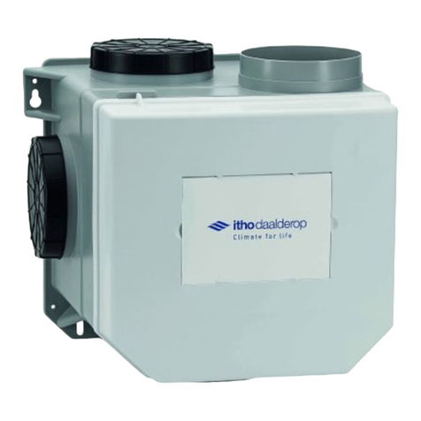
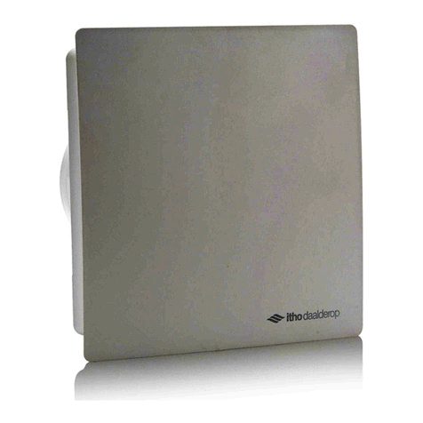
Itho Daalderop BTV-N200 User manual

1
Itho Daalderop
BTV-N200
Manual

2
1.
Safety & regulations
1.1.
Safety
●Work on the ventilation system may only
be carried out by authorized fitters (1) in
accordance with the instructions in the
manual. Only accessories and spare parts
prescribed by the manufacturer may be
used.
●Do not use the product for purposes
other than those specified in this
manual.
●Handle electrical appliances with
care:
-
Never touch the device with wet
hands.
-
Never touch the device when you are
barefoot.
●This product and/or system may be
operated by children aged 8 and above
and by persons with reduced physical,
sensory or mental capabilities, or lack of
experience and knowledge, if they are
supervised or instructed in how to use it
safely and are aware of the hazards of
the product and/or system.
●Cleaning and maintenance by the user
must not be carried out by children or by
persons with reduced physical, sensory or
mental capabilities, or lack of experience
and knowledge, without supervision.
●Prevent children from playing with the
product and/or system.
●Do not use the product in the presence
of flammable or volatile substances such
as alcohol, insecticides, petrol, etc.
●The unit must absolutely NOT be used for
the discharge of hot air into ducts
intended for the flue gas of stoves or
other combustion appliances. The air
must be discharged directly to the
outside.
●If, in the same room where the appliance
is installed, there is also a fuel-fired
appliance (water heater, gas heater, etc.,
without an enclosed combustion
chamber), it is necessary to check that
enough new air can enter the room to
ensure proper combustion in these
appliances, taking precautions to prevent
gases coming from the gas exhaust pipe
or from other fuel-fired appliances from
escaping back into the room.
●The unit must not be used to control
fans, other heaters, etc.
●Do not obstruct the air supply or the air
outlet in any way. Also check that the
air conduction systems are not blocked
or closed.
●It is essential that there is a sufficient
supply of air in the room where the unit is
installed at all times.
●The air to be discharged with the unit
must be clean, i.e. free from grease,
soot, chemical and corrosive
substances, flammable or explosive
mixtures.
●Do not immerse the device or its parts in
water or other liquids.
●Do not use the product at an
ambient temperature above 40°C.

3
●Safety instructions must be followed in
order to avoid physical injury and/or
damage to the product.
●Maintenance and cleaning may only
be carried out after the appliance
has been disconnected from the
power supply.
●The product contains rotating parts.
Therefore, after disconnecting the
power supply, wait at least 10 seconds
before opening or touching the product,
as these parts continue to rotate for
some time.
●Secure the system against
unintentional reactivation.
●Maintenance instructions must be
followed to prevent damage and
excessive wear.
●The product must not be modified.
●The product is only suitable for a 230
V 50 Hz AC system.
●Make sure that the electrical system
to which the product is connected
fulfils the stipulated conditions.
●The connection systems to the power
supply system must allow complete
disconnection during Category III
overvoltage conditions.
●Do not expose the product to
weather conditions.
●Do not place any objects on top of the
device.
●Regularly inspect the product for defects.
In case of defects, switch off the product
and contact your installer or the Itho
Daalderop service department
immediately.
●Never switch off the product except
when:
-
The product does not function
properly.
-
You want to clean the product.
-
Want to carry out
maintenance on the device.
-
The government advises to close
windows and doors in case of calamity.
●Take care not to damage the electrical
circuit.
●Do not use the unit for extracting water
boilers, heating systems, etc.
●Make sure that the appliance drains into
a drain that is suitable and laid out for
this purpose and that drains to the
outside.
●Keep valves free and clean.
●If the power cable is damaged, it must
be replaced by the manufacturer, his
agency or a qualified person in order to
avoid danger.
●The user/consumer must not open the
device.
*) A recognised installer is an installer working at a central heating or
mechanical installation company that is registered with the Chamber
of
Commerce and listed in the SEI recognition register (Stichting Erkenning
Installatiebedrijven) or that has Sterkin recognition.

4
Warning!
The specifications and settings of the appliance comply
exclusively with the standards and laws of the country in
which the appliance is sold.
Applications outside this country can lead to very
dangerous situations!
1.1.1.
Standards and guidelines
The installer must ensure that the entire installation meets
the legal requirements, the regulations contained in this
document and any other applicable manufacturer's
documentation.
For all legal requirements and regulations, supplements,
amendments or legal requirements and regulations that come into
force later apply at the time of installation.
After installation, there must be no more safety, health and
environmental risks in accordance with the applicable CE directives.
This also applies to other products included in the installation.

5
2.
Product information
The BTV-N200 is a fan with a propeller for direct air extraction,
possibly via a short pipe, suitable for installation in the wall or
ceiling.
2.1.
Versions
Article
Type Description
53-00350
BTV-N200
Bathroom and toilet fan white,
53-00351
BTV-N201 T
Bathroom and toilet fan white,
and Timer
53-00352
BTV-N202 H
Bathroom and toilet fan white,
and Hygrostat*
53-00353
BTV-N203 HT
Bathroom and toilet fan white,
Timer and Hygrostat*
53-00354
BTV-N211 T
Bathroom and toilet fan white,
and Timer
*
These versions are equipped with a non-return valve. The purpose of the
non-return valve is to prevent the hygrostat from starting up
unintentionally due to condensation when the temperature falls at night.
2.2.
Technical specifications
Description
Symbol
Unit
BTV
N200
N201 T
N202 H
N203 HT
N211 T
DIMENSIONS AND WEIGHT
Dimensions (HxWxD)
- —
mm
186 x 160 x137
Weight
- —
kg
0,69
CONNECTIONS
Outer diameter
- —
mm
Ø 98 external
GENERAL
Colour
- — - — RAL 9003
Matt silver
IP classification
- — - — IPX4*
Safety class
- — - — II; double insulated
Supply voltage - — - —
~ 230V - 50Hz
Power connection
- —
- —
zero
+switch
wire
zero + phase + switch wire
Post-running time (adjustable) - —
minus
-
-3-25
-
-0.5-20 -3-25
Bearings
- — - —
Plain Bearings
TECHNICAL PARAMETERS
Maximum flow rate
m3/h 78
Electrical input power of the fan drive - —
W
11,7
APPLICATION
Temperature range
°C 0-40
Relative humidity range
%
5-95 (non-condensing)
*
According to standard IEC 60529 2001-02

6
2.3.
Product card information
Itho Daalderop
BTV
Description Symbol Unit N200 N201T N202H N203HT N211T
Specific energy consumption class
- —
- —
F
D
Specific energy consumption, under cold climate conditions
SEC
kWh/(
m2
.a)
-22
-48
Specific energy consumption, under moderate
climate conditions
SEC
kWh/(m2.a)
-9
-23
Specific energy consumption, under warm climate conditions
SEC
kWh/(m2.a)
-1
-8
Type of ventilation unit VE - —
Residential ventilation unit (RVE) One-way ventilation
unit (EVE)
Type of drive
- —
- —
On/Off
Type of heat recovery system
HRS
- —
No
Thermal efficiency of the heat recovery system
ƞt
%
Not applicable
Maximum flow rate
qmax
m3/h
78
Electrical input power of the fan drive, at
maximum flow rate
Pmax
W
11,7
Sound power level
LWA
dB
54
Reference flow
qref
m3/s
0,0206
Reference pressure difference
ΔPref
Pa
10
Specific input power SPI W/(m3/h)0,158
Ventilation control
- —
- —
Manual control (no DCV)
Control factor
CTRL
- —
Manual
Local
Percentage for external leakage for one-way ventilation
units with air ducts
- —
%
Not applicable
Instructions for installing regulated suction/intake
extraction grilles in the facade for natural air intake/exhaustion - — - — Not applicable
Instructions for pre-assembly/disassembly - — - —
Airflow sensitivity to pressure variations at + 20 Pa and
- 20 Pa
- — - — Not applicable
Air tightness between inside and outside - — - — Not applicable
Annual electricity consumption
AEC kWh
218
142
Heating saved annually, under cold
climate conditions
AHS
kWh 2732
5131
Annual heating savings, under moderate
climate conditions
AHS
kWh 1397 2623
Heating saved annually, under warm
climate conditions
AHS
kWh 632
1186

7
2.4.
Scale drawings
2.5.
Scope of delivery
1
2
3
Legend
1
Fan
2
Fixing material
3
Documentation
2.6.
Unpacking and checking
a)
Carefully take the equipment out of the box.
b)
Check the nameplate data and the type for correctness as
shown on the sticker on the box.
c)
Check the equipment for damage and completeness.
d)
Check whether the appliance is packed with the necessary
documentation and accessories.

8
2.7.
Arrangements
2.7.1.
Standard regulation
The BTV-N200 is the standard version with standard control only.
With this standard control, the fan starts ventilating at high speed
as soon as it is switched on and continues until it is switched off by
the (light) switch.
2.7.2.
Timer control
The BTV-N201 T , the BTV-N203 HT and the BTV-N211 T are equipped
with
a time switch and are ideal for applications where post-
ventilation is required, such as toilets. The fan is switched on via
the light switch or a separate switch and continues to run for
approximately 10 minutes after it is switched off. The so-called
follow-up time is set at approx. 10 minutes on delivery. If required,
this time can be changed by turning the potentiometer.
2.7.3.
Hygrostat control
The BTV-N202 H and BTV-N203 HT are equipped with a humidity
control. The humidity control switches on automatically if the
humidity level in the room exceeds the set value. The switching
point (relative humidity) can be set between 40% and 95% using
the setting potentiometer. After the relative humidity has fallen to
the setpoint (and with the HT version also the delay time has
expired), the fan will switch off.
2.7.4.
Operating the fan
The BTV models are operated with the light switch or a separate
switch. As soon as the switch is turned on, the fan starts to
ventilate in high speed. After switching off with the switch, the fan
switches off.
2.8.
Recycle
Sustainable materials have been used in the manufacture of this
product. This product must be disposed of responsibly at the end
of its life cycle. The government can provide you with information
about this.
The product packaging is recyclable. These materials must be
disposed of responsibly and in accordance with official regulations.
In order to draw attention to the obligation to separate batteries
from household electrical waste, the product bears the symbol of a
waste bin with a cross through it. This means that the product must
not be disposed of with normal household waste at the end of its
service life. The product must be taken to a specialised waste
collection centre in the municipality or to a point of sale that
provides this service.
The separate disposal of batteries and household appliances avoids
possible negative consequences for the environment and health
caused by inappropriate treatment. It ensures that the materials
that make up the appliance can be recovered to achieve significant
savings in energy and raw materials.

9
3.
Installation
3.1.
Installation requirements
Please observe the following before installation: Mount
the BTV:
●At a height of 2.3 metres above the ground in the wall, or in
the ceiling (not in the floor or in a sloping wall!).
●In a room where there is sufficient supply air.
●
in the vicinity of a 230 V, 50 Hz wall socket.
Ensure low resistances by using as many short, straight and
smooth ducts as possible. When using flexibles, we recommend
using a larger duct diameter. Also use a wall duct with low
resistance.
The fan is suitable for a connection diameter of 100 mm.
Placement against a connection diameter up to 125 mm is
possible, but may slightly affect performance.
Warning!
When using a cable tray, a suitable power cable with an outer
diameter of 5 to 7 mm must be passed through the rubber cable
duct and strain relief provided.
Warning!
Before starting the electrical installation (connecting the
wiring), de-energise the group to which the fan is connected.
Do not re-energise the group until AFTER the installation has
been completed.
Warning!
Never connect the device with an extension lead!
Warning!
Never connect the device with a damaged power cable!
3.2.
Installing the fan
The BTV-N200 series bathroom and toilet fan should be mounted in
the wall or the ceiling.
c) Drill the necessary holes for the plugs supplied. Use the rear
part of the fan itself as a marking template or use the
dimensional drawings.
Mount the fan as follows:
a)
Make sure that any remaining dirt is removed from the hole.
b)
Check whether there is a power supply connection at the
location where the fan is to be installed.
d)
Insert the supplied plugs.
Warning!
The duct to the outside must be leak-tight connected to the
fan and installed at a slope.
Warning!
The fan should discharge the exhaust air directly to the outside.
6 mm

10
e)
Drill a hole for the power cable in the rear of the enclosure,
or go to step f if a cable tray is used. Go to step h if no cable
tray is used.
f)
Power supply connection with cable duct:
i) Mount the cable using the strain relief provided. Connect the
wiring as indicated in the chapter "
Connecting the
power
supply
".
j) Mount the cover plate on the fan and screw it into place.
g)
Prepare and mount the supplied wire grommet on the top
side.
k) Replace the housing.
h)
Place the fan (with the supplied white foam between the wall
and the fan to reduce vibrations and air leakage) and screw it
into the wall or ceiling.

11
Warning!
When using a cable tray, a suitable power cable with an outer
diameter of 5 to 7 mm must be passed through the rubber cable
duct and strain relief provided.
*
L
N
L
N
L
L
N
*
N
3.3.
Electric connection
Mounting the power cable under the strain relief
Wiring diagram BTV-N200
Connection of light point
Connection diagram for BTV-N201T, N202 H, N203 HT and 211 T
*
Connection of light point
Note
Use a short duct and outer wall grille with as little resistance
as possible.

12
TIMER
3
25
-
HY%
40
95
-
Warning!
If the fan is internally contaminated, it must be cleaned by a
recognised installer. The user/consumer must not unscrew
the device. However, the decorative cap can be removed to
wipe the surfaces with a slightly damp cloth.
4.
Set up
4.1.
Setting the Timer
4.2.
Setting the Hygrostat
The timer (delay time) can be set. On delivery, the shut-off delay
is set to approximately 10 minutes. If required, this time can be
altered by turning the adjusting potentiometer (behind the
curved trim panel) from 3 minutes (anti-clockwise) to 25 minutes
(clockwise). The time must be
determined
by experiment
.
Switching on by the humidity switch takes place automatically if
the humidity level in the room exceeds the set value. The
switching point (relative humidity) can be set between
40%
(counterclockwise) and 95% (clockwise) by means of the
setting
potentiometer. The adjusting potentiometer is located behind the
decorative plate.
5.
Service & Maintenance
The fan requires little maintenance. Wiping with a slightly
damp cloth is usually sufficient.
OFF
ON

13
6.
Faults
Warning!
The user/consumer must not open the device!
The fan does not run any more
Cause
Solution
a) The main switch is in the OFF position.
●
Set the main switch to On.
b) The fan is not (properly) electric
connected.
●
Connect the fan correctly electrically.
c) The fan is jammed due to extreme contamination.
●Clean the fan. Internal cleaning
may only be carried out by a
The work must be done by a recognised
installer.
d) The fan is defective. ●Replace the entire fan.
The fan makes (too) much noise
Cause
Solution
a) The fan is not properly mounted. ●Mount the fan correctly (with the
supplied with dowels and screws).
b) The drain has a lot of resistance. ●Clean the duct. Internal cleaning
may only be carried out by a
The work must be done by a recognised
installer.
c) The fan is running. ●Clean the fan. Internal cleaning
may only be carried out by a
The work must be done by a recognised
installer.
d) The fan is jammed due to deformation of the
housing. The ring in which the non-return valve
mounted is taken off
●
Replace the attachment ring on the
round housing part. The non-return
valves
may be removed.
e) The fan is defective.
●Replace the entire fan.
The fan does not discharge enough air
Cause
Solution
a) The installation has too much resistance (dirt,
long, curved, flexible duct, external wall grille
is closed, etc.).
●Remove the resistors from the fan.
Internal cleaning may only be
performed by a recognised installer
be done.
b) There is insufficient air supply in the room. ●Make sure that sufficient air can be
supplied, for example at least 3 cm
under the door.

14
7.
Warranty
For all Itho Daalderop products, a standard factory guarantee
of two years applies. Within this period, the product or its
parts will be repaired or
replaced
free of charge
.
Provisions and exclusions are included in our
guarantee conditions.
Please refer to the product's page on our website for full
warranty terms and/or additional warranty terms or conditions.
If there are problems with the operation of our product, we advise
the consumer to consult the manual first. If the problems persist,
please contact the installer who installed the product or the Itho
Daalderop service department. You will find the contact details at
the end of the manual or on our website.

15
DirectivesHarmonised
European standards
-EN
ISO 5801:2017
Directive 2009/125/EC (Ecodesign)
Directive 2011/65/EU
EN
IEC 63000:2018
8.
Statements
EC declaration of conformity
Itho Daalderop Group BV
PO Box 7
4000 AA Tiel
Netherlands
Declares that the following ventilation units comply with
the following directives and standards.
-
BTV-N200, Bathroom and Toilet Fan White
-
BTV-N201T, Bathroom and Toilet Fan White, with Timer
-
BTV-N202 H, bathroom and toilet fan white, with Hygrostat
-
BTV-N203 HT, Bathroom and Toilet Fan White, with Timer and Hygrostat
-
BTVZ-N211T, bathroom and toilet fan matt silver, with timer
Directive 2014/30/EU (EMC)
-
EN 55014-1:2017+A11:2020
-
EN 55014-2:1997 +AC:1997 +A1:2001 +A2:2008
-
EN 62233:2008 +AC:2008
-
EN 61000-3-2:2014
-
EN 61000-3-3:2013
Directive 2014/35/EU (LVD)
-
EN 60335-1:2012 +AC11:2014 +A13:2017
+A1:2019 +A2:2019 +A14:2019
-
EN 60335-2-80:2003 +A1:2004 +A2:2009
Tiel, 1 April 2021.
Coen Schut
Innovation Manager Ventilation
This manual suits for next models
9
Table of contents
Other Itho Daalderop Fan manuals