7
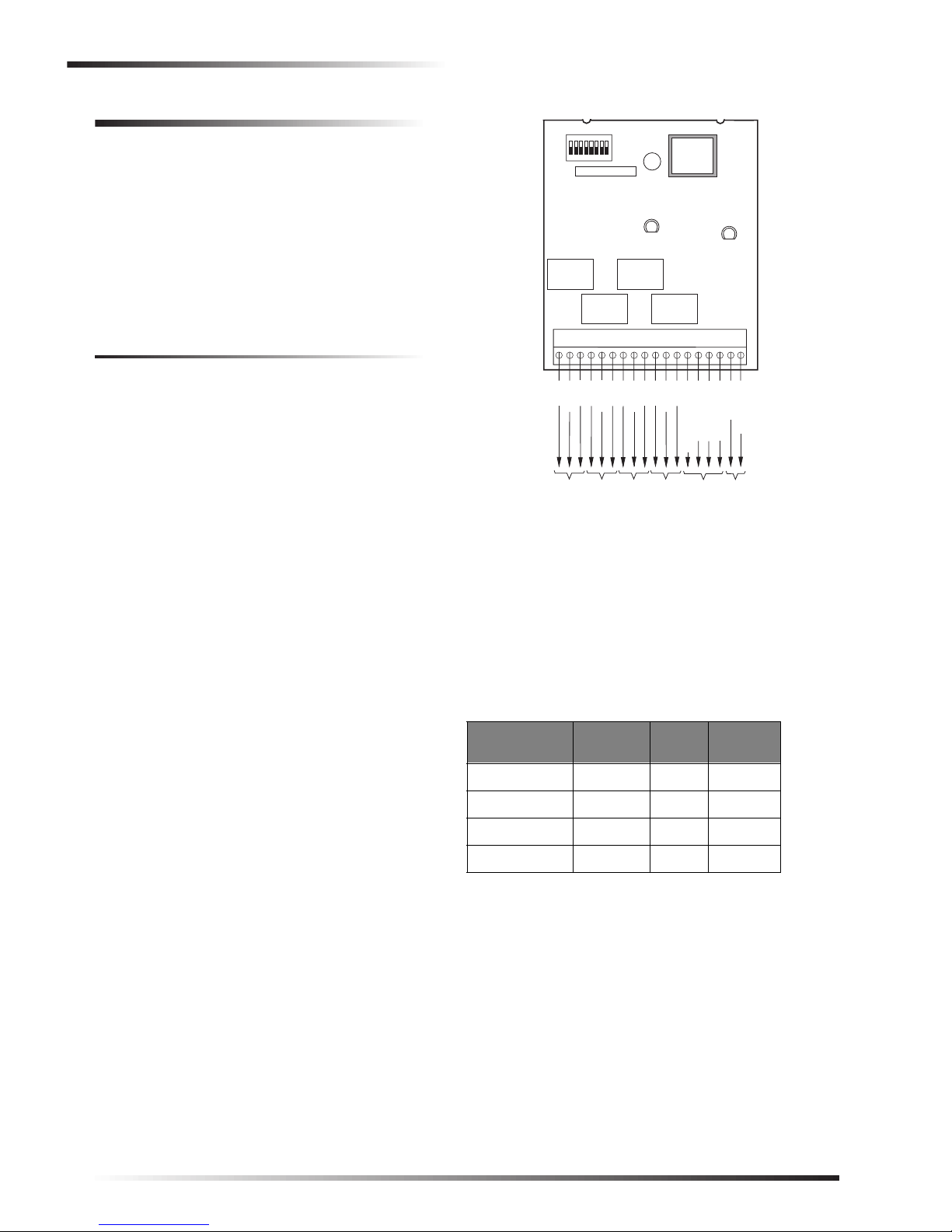
SuperBus® 2000 4-Relay Output Module
Programming and Testing
2. Connect the panel battery(s) and restore panel AC
power. Alphanumeric touchpad displays should come
on. Both the green and red LEDs turn on for one sec-
ond, then the green POWER LED will remain on.
3. Press 8for System Menu.
4. Press 0for Program Menu.
5. Enter your Install Code (default 0123).
6. Enter Item Number 48001 to add SuperBus 2000
devices. All installed devices are automatically added
(learned) into panel memory when Devices Added is
indicated.
7. Press * twice to return to the Main Menu.
8. The red BUS status LED should flash to indicate suc-
cessful communication with the panel.
Note
If the green POWER LED is not on or the red BUS
status LED does not flash, remove AC panel power,
disconnect the battery(s), and see Table 6 “Trouble-
shooting.”
UltraGard Panels
1. Verify that all wiring at the panel and the module is
correct.
2. Verify nonconflicting bus unit number settings.
3. Connect the panel battery and restore panel AC power.
4. Turn on the panel AC power.
5. Set the UltraGard panel RUN/PROGRAM switch to
PROGRAM.
If the alphanumeric touchpad displays 1-OFF and the 1is
flashing, you must enter the 4-digit installer access code to
get the panel into program mode.
Alphanumeric touchpads should display PROGRAM
MODE and the red BUS status LED on the module should
be flashing continuously, indicating successful communica-
tion to the panel.
Note
If the green POWER LED is not on or the red BUS
status LED does not flash, set the RUN/PROGRAM
switch (UltraGard) to RUN, remove AC panel power,
disconnect the backup battery, and see Table 6 “Trou-
bleshooting.”
Programming and Testing
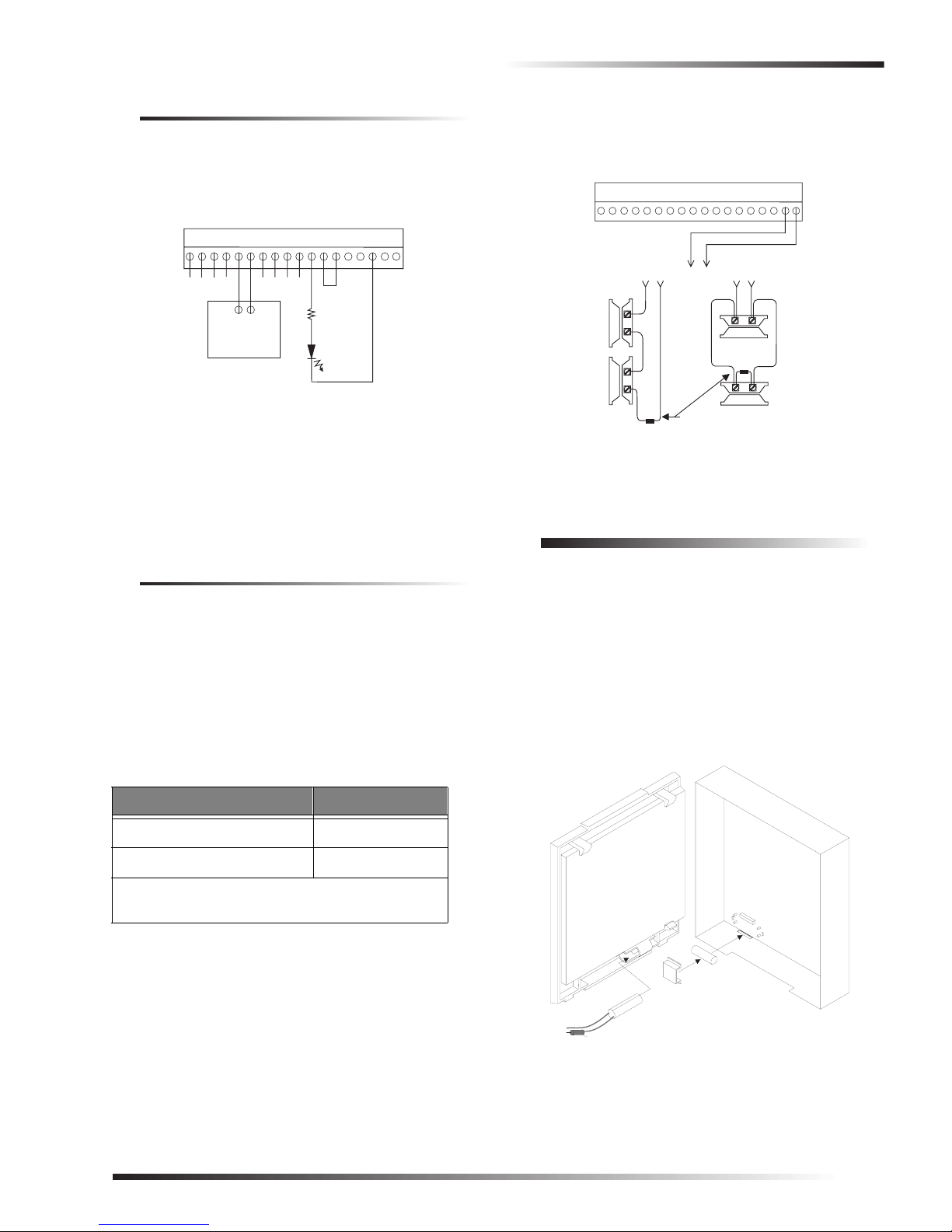
Refer to the specific panel Installation Instructions for
configuring module outputs, adding (learning) hardwire
sensors, and testing.
Troubleshooting
Use the following table to determine possible solutions to
module problems.
Table 6: Troubleshooting
Problem Solution
The green POWER
LED stays off. 1. Check for incorrect wiring con-
nections.
2. Make sure panel AC power is
applied and the backup battery(s)
are connected.
3. If the LED still remains off,
replace the module.
The red BUS LED
doesn’t flash to
indicate
communication
with the panel.
1. Verify that the panel recognizes
the module by entering program
mode (see specific panel Installa-
tion Instructions).
2. Check for incorrect wiring con-
nections.
3. For Concord (software versions
1.0–1.6) and UltraGard panels
make sure that module DIP switch
1 is set to “M.” For Concord (soft-
ware versions 2.0 or later) and
Advent panels make sure that
module DIP switch 1 is set to “A.”
4. If the LED still doesn’t flash,
replace the module.
Output(s) activate
only momentarily,
activate randomly,
or module and/or
touchpads lock up.
1. For Concord (software versions
1.0–1.6) and UltraGard systems,
check for bus devices with the
same unit number setting.
2. Re-initialize the panel by discon-
necting and reconnecting panel
power.
3. Verify that the output/point is con-
figured correctly (see specific
panel Installation Instructions).
4. Make sure the zone has been
“learned” into panel memory.
5. Verify that the panel recognizes
the module by entering program
mode (see specific panel Installa-
tion Instructions).
6. Check module/panel wire routing
and length.
7. Replace the module.
Module Zone input
is inoperable.
(UltraGard &
Concord)
1. Some panels and panel versions
do not read the module built-in
zone input status. Use a panel zone
input instead.
One output stays
activated. 1. Check if the point is programmed
for a 3 minute “on” time and if the
triggering event for the point is
repeatedly “resetting” the 3
minute timer (see specific panel
Installation Instructions).
2. Output may have failed or been
overloaded. Reprogram using a
different (unused) module output
or replace the module.