ITR WindowWasher User manual

from Calcutt Boats
Installation and
Operating Manual
Diesel Fired Continuous Output
Window Cleaning Water Heater

Copyright © January 2010
MANUFACTURED BY: SOLE EUROPEAN DISTRIBUTORS:
International Thermal Research Calcutt Boats Ltd.
2431 Simpson Road, Tomlow Road, Stockton,
Richmond, BC, Canada, V6X 2R2 Southam, CV47 8HX, UK
Tel: +1 604-278-1272 Tel: +44 1926 813757
Fax: +1 604-278-1274 Fax: +44 1926 814091
Website: www.itrheat.com Website: www.dieselheating.com
All rights reserved. No part of this manual may be reproduced
or transmitted in any form by any means, electronic or
mechanical, including photocopying and recording, information
storage, retrieval, or transmission, without permission in
writing from International Thermal Research and/or Calcutt
Boats Ltd.
Disclaimer:
Due to our commitment for quality and ongoing product
improvement, ITR & Calcutt Boats reserve the right to modify or
change without notice, any materials, applications, equipment,
accessories, and/or prices. All measurements and weights are
approximate.

International Thermal Research i
Table of Contents
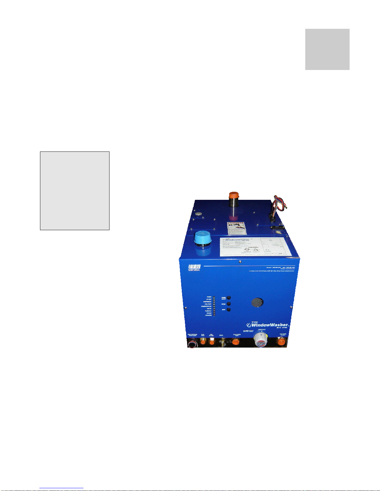
Section 1, Overview...................................................... 1
1.1 Unpacking the WindowWasher...................... 2
1.2 Protect Your Warranty................................. 2
1.3 The WindowWasher™ by ITR Features ........... 3
1.4 Critical Factors ........................................... 4
1.5 Equipment, Tools and Skills.......................... 4
1.6 Testing and Inspection ................................ 5
Section 2, Mounting the WindowWasher....................... 7
2.1 Before You Begin........................................ 7
2.2 Your Mounting Location ............................... 8
2.3 Procedure.................................................. 9
Section 3, Installing the Exhaust System.................... 11
3.1 Before You Begin...................................... 11
3.2 Mounting Location..................................... 11
3.3 Procedure................................................ 13
Section 4, Installing the Fuel System.......................... 15
4.1 Before You Begin...................................... 15
4.2 Fuel System Installation ............................ 15
4.3 What NOT to Do ....................................... 16
4.4 Procedure................................................ 17
Section 5, Wiring the Electrical System ...................... 19
5.1 Before You Begin...................................... 19
5.2 12 VDC ................................................... 19
5.3 Remote Operating Panel Cable.................... 20
5.4 Main Electronic Control Board..................... 20
5.5 What NOT to Do ....................................... 20
Section 6, Plumbing the System ................................. 23
6.1 Before You Begin...................................... 23
6.2 Plumbing Installation................................. 23
6.3 What NOT to Do ....................................... 25
6.4 Installation Procedure................................ 25
Section 7, Operating The WindowWasher™ ................ 27
7.1 Operating Instructions............................... 27
7.2 Turning the Power “ON”............................. 28
7.4 Functions of the Remote Panel.................... 28
7.5 Functions of Control Panel.......................... 29

Table of Contents
ii WindowWasher Installation Manual
7.6 WindowWasher Maintenance.......................31
7.7 Protect the WindowWasher™ ......................33
7.8 General Troubleshooting ............................33
Section 8, Warranty Information.................................35
List of Figures
Figure 1-1: WindowWasher Unit .....................................1
Figure 2-1: Dimensions .................................................9
Figure 2-2: Location of Mounting Brackets...................... 10
Figure 3-1: Installing the Exhaust System...................... 14
Figure 5-1: System Wiring ........................................... 20
Figure 6-1: Plumbing Fittings ....................................... 23
Figure 7-1: The WindowWasher - Fittings....................... 27
Figure 7-2: Remote Operating Panel.............................. 29
Figure 7-3: The WindowWasher - Control Panel............... 30

International Thermal Research 1
Section 1, Overview
Thank you for purchasing The WindowWasher™ by ITR for
the window cleaning trade.
This section describes features of The WindowWasher™ by
ITR and covers critical information you need to know before
beginning the installation, including how to protect your
warranty, and tools and equipment needed.
Figure 1-1: WindowWasher Unit
Section
1
Some of the figures
in this manual
represent a typical
installation, but
other configurations
or methods may be
acceptable. If in
doubt, obtain
approval from
Calcutt Boats or ITR.

Section 1, Overview
2 WindowWasher Installation Manual
1.1 Unpacking the WindowWasher
When you receive The WindowWasher™ by ITR:
1 Unpack it carefully.
2 Check each component against the provided parts list to
ensure that you have everything and that all parts
arrived undamaged.
3 If you discover any missing or defective parts, call
Calcutt Boats or ITR immediately.
4 If you are not installing The WindowWasher™ by ITR
right away, secure all components so none will be
misplaced.
5 Before installing The WindowWasher™ by ITR, read
the rest of Section 1 – Overview. It contains
critical information for a proper installation.
A properly installed WindowWasher™ by ITR is essential for
several reasons:
•To ensure that you and/or your customers receive
satisfactory results.
•To ensure a trouble-free installation, a successful
inspection and testing process and ease of future
maintenance.
•To protect your Warranty.
1.2 Protect Your Warranty
This document reflects approved installation techniques,
methods, and materials, and applies only to ITR equipment.
The WindowWasher™ by ITR is only guaranteed by ITR if the
entire system has been installed according to the
requirements and recommendations set out here.
Any modification must be approved in writing by
qualified Calcutt Boats or ITR personnel, prior to the
installation.
This includes:
•Deviations from the instructions in this Manual.
•Changes to any piece of ITR-supplied equipment.
•Substitution of a non-ITR-approved component.
NOTICE

Section 1, Overview
International Thermal Research 3
No warranty will be extended to improper installations. Use
of any unapproved materials, equipment, or installation
procedures will result in a voided warranty for the entire
system. Calcutt Boats and ITR accept no liability for any
damage or loss of service resulting from unapproved
modifications.
1.3 The WindowWasher™ by ITR
Features
The WindowWasher™ by ITR uses a patented diesel burner
(12 VDC) controlled by a multi-functional electronic controller
as the primary source of heating water. The
WindowWasher™ by ITR heats water to provide a continuous
supply for window cleaning.
Other features of The WindowWasher™ by ITR include:
•A high-temperature, stainless steel burner and
stainless steel jacket.
•5.3 US gallon (20.5 L) welded stainless steel
insulated water tank that minimizes heat loss and
optimises heat recovery.
•Low water level switch in the tank.
•Easy to install with hook-ups and connections easily
accessible from the top and front of The
WindowWasher™ by ITR.
•Quiet operation and low power consumption.
•Low pressure fuel system with built-in fuel pump.
•Fuel efficient burner capable of burning a wide
variety of diesel-based fuels.
•Exhaust has minimal smoke or smell.
•Fan assisted sealed combustion chamber is designed
to use outside air.
•Simple, low amperage draw ignition.
•Electronically-controlled system with:
oAutomatic Safety Shutdown.
• Efficient
• Clean
• Quiet
• Compact
• Safe
• Rugged
• Reliable
• Economical

Section 1, Overview
4 WindowWasher Installation Manual
oManual reset aquastats for safety overheat
protection.
oLED indicators on the Control Panel for
diagnostics.
oPatented, proprietary flame sensor.
•The WindowWasher™ by ITR Remote Operating Panel
with ON/OFF switch for the diesel burner and
indicator LEDs for operational and diagnostic
information.
1.4 Critical Factors
The key factors to keep in mind when planning and carrying
out the installation are:
•Mounting location restrictions for The
WindowWasher™ by ITR exhaust outlet (to reduce
noise, vibration, heat loss, etc.)
•Length, routing, and sizing of fluid lines, fuel lines,
air flow tubing, exhaust piping and wiring.
•Unrestricted intake required to draw in outside air for
combustion.
•Ability to easily access and service the product,
especially fuel, plumbing, and electrical systems.
•After installation, requirement to purge water and
fuel lines and inspect/test entire system using the
ITR-supplied Inspection Check Sheet.
1.5 Equipment, Tools and Skills
As the user and/or installer, you must be qualified and
authorized to do the installation, which requires mechanical
aptitude and electrical knowledge. Make sure you comply
with existing industry practices, using the highest and most
recent standards and codes. Good workmanship is essential.
Please refer back to Section 1.2, Protect Your Warranty.
You will need the following equipment and tools (not
supplied) to install the heating system. This list does not
include optional equipment and accessories:
•Standard tools normally available in a well-equipped
workshop.
•Appropriate fasteners for mounting the heater unit.
Pay attention to the
notices of “Danger”
“Warning” “Caution”
and “Notice” in this
manual.

Section 1, Overview
International Thermal Research 5
•Stainless steel 1-1/2” ID exhaust piping, maximum
12’ with no bends (see Section 3 – Installing the
Exhaust System, for details when bends are present).
•Optional ITR silencer.
•1/4” supply and return fuel line, approved rubber or
copper.
•Domestic water hose and/or tubing to connect The
WindowWasher™ by ITR hose fittings to the van
water system.
1.6 Testing and Inspection
After all components have been properly installed according
to standard practices, and the recommendations of this
Installation and Operating Manual, The WindowWasher™ by
ITR should be test-operated for inspection purposes.
For your convenience, you can use the pullout Inspection
Check Sheet in this Manual. The Inspection Check Sheet is
divided into progressive sections, allowing each phase of
the inspection to be carried out systematically, and then
signed off by authorized persons.

Section 1, Overview
6 WindowWasher Installation Manual

International Thermal Research 7
Section 2, Mounting the
WindowWasher
2.1 Before You Begin
Plan the location of The WindowWasher™ by ITR and all its
major components in advance to ensure the chosen locations
are feasible and within the technical specifications.
Consider the following factors to help you decide exactly
where best to mount The WindowWasher™ by ITR:
•The WindowWasher™ by ITR weight when full.
•Ventilation requirements.
•Exhaust outlet location and maximum acceptable
length.
•Through van body exhaust location.
•Potential for vibration and jarring.
•Fuel storage location.
•Most efficient plumbing runs.
•Safe and convenient access for maintenance.
•Location of other equipment to be installed or
connected to The WindowWasher™ by ITR.
Make sure you are familiar with Section 1 – Overview of
this Manual. If the system is not installed according to
specifications and with the correct equipment, The
WindowWasher™ by ITR may not operate properly, safety
may be compromised, and your Warranty may be voided.
Section
2
!
W
ARNING

Section 2, Mounting the WindowWasher
8 WindowWasher Installation Manual
2.2 Your Mounting Location
Your mounting location should consider the following:
•Mounting location must be able to support double
the gross weight of The WindowWasher™ by ITR
(i.e. 150 lbs. x 2 = 300 lbs/68 KG x 2 = 136 KG)
and must be of a non-combustible surface.
•The WindowWasher™ by ITR is 14”H x 14”W x
24”D (35.6 cm x 35.6 cm x 60.9 cm). See Figure
2-1: Dimensions.
The WindowWasher™ by ITR must not be installed in any
compartment with flammable gasses.
•The WindowWasher™ by ITR must be completely
isolated from living spaces. Combustion air must
be drawn from a 100% outside source and cannot
contain any combustible gasses.
•The WindowWasher™ by ITR must be mounted in
an area that provides unrestricted access to the
front panel mounted fuel and water connections,
and top mounted power and exhaust connection
(minimum of 10” top clearance) and 3” clearance
to all other WindowWasher™ surfaces.
•The WindowWasher™ by ITR must not be installed
in any compartment with flammable gasses.
•The WindowWasher™ by ITR must be mounted
horizontal and level using eight (8) x 1/4” through
bolts using 1” diameter washers, lock washers
and nuts.
•It is recommended that a catch tray be placed
under The WindowWasher™ by ITR for containing
any unexpected leakage.
If The WindowWasher™ by ITR is going to be mounted in
the engine compartment, check for adequate ventilation.
When the engine is running, this area could be under a
negative pressure. Make sure the air intake and exhaust
hoses have no leaks and are well-fastened to the heater,
silencer and through van fitting. Assembly parts that may
cause injury through accidental contact should be
protected.
! CAUTION
NOTICE

Section 2, Mounting the WindowWasher
International Thermal Research 9
Isolate the unit in a closed compartment so that no air from
the heater will infiltrate the vehicle cab.
•Choose a sturdy surface in a location that won’t be
unduly affected by vibration and the jarring of rough
roads.
•Mount the unit with the front panel side facing out
and accessible. Facing out simplifies installation and
maintenance.
•Open access is required to properly service the
heater. Leave room at the front, and top of the unit.
•Ensure that the exhaust tubing can be properly and
safely routed to the outside. The maximum exhaust
run for the system is 12’.
Figure 2-1: Dimensions

Section 2, Mounting the WindowWasher
10 WindowWasher Installation Manual
2.3 Procedure
After choosing the mounting location for The
WindowWasher™ by ITR:
1 Mount The WindowWasher™ by ITR horizontally and
level.
2 Secure The WindowWasher™ by ITR in place (against
the wall, floor, or a mounting platform) using eight (8) x
1/4” through bolts
using 1” diameter fender washers,
lock washers and nuts (See Figure 2-2: Location o
f
Mounting Brackets.).
Figure 2-2: Location of Mounting Brackets

International Thermal Research 11
Section 3, Installing the
Exhaust System
3.1 Before You Begin
For efficient and safe operation of The WindowWasher™ by
ITR follow all recommendations for properly installing the
exhaust. Any deviations from these must be approved in
advance by Calcutt Boats or ITR.
Although the heater’s exhaust produces very low carbon
monoxide emissions, caution is still advised:
•Do not operate The WindowWasher™ by ITR in an
enclosed area unless there is adequate ventilation.
•Isolate The WindowWasher™ by ITR in a closed
compartment so that no air from the unit will
infiltrate the vehicle cab.
Never place any exhaust parts close to combustible material
or through a combustible wall or ceiling without fireproof
protection. The exhaust can reach high temperatures.
3.2 Mounting Location
If you can’t meet the technical specifications for mounting
the exhaust, don’t use The WindowWasher™ by ITR. The
unit may perform poorly or become damaged if not installed
according to specifications.
Section
3
!DANGER

Section 4, Installing the Fuel System
12 WindowWasher Installation Manual
Recommended Exhaust Outlet Locations
The following is recommended for a van exhaust outlet
location:
Mount the exhaust outlet outside the van, not inside the
heater compartment. Otherwise, exhaust fumes could
infiltrate the van from The WindowWasher™ by ITR
compartment.
In a van, the typical mounting location for the exhaust outlet
is under the floor of the heater compartment, or on the other
side of the van, directly across from the heater unit. Keep in
mind you cannot exceed 12’ of exhaust piping, including
bends.
Position the outlet of the exhaust pipe so that the exhaust
exits off the side of the van, not towards the front, back, or
under an opening window, vent or slide-out.
Recommendation for Installation
You may use sweep bends but each 90° bend is equivalent to
one foot of exhaust piping. For example, if you use two 90°
bends you must deduct one foot per bend from the
maximum allowed 12’ straight exhaust pipe length.
Therefore you will be restricted to 10’ of straight exhaust
piping plus the two bends. Do not exceed these
recommendations.
The combustion air-intake must use 100% outside air.
Use an ITR-manufactured silencer; no other silencer is
acceptable.
Exhaust outlet is on the top of The WindowWasher™ by ITR,
towards the back.
The exhaust and outlet are HOT and the surrounding areas
must be thermally shielded and protected from the hot
surfaces and heat build-up by insulation. Nothing can come
into inadvertent contact with any part of the exhaust
system
Exhaust pipe must have a minimum of 3” (7.6 cm) clearance
from all surfaces.
Ensure that the exhaust cannot be plugged or restricted.
The exhaust fitting on The WindowWasher™ by ITR is
1.5” O.D. and the exhaust pipe used must have a minimum
of 1.5” I.D throughout its length.
All exhaust elbows must be of a large radius design
(minimum radius 2.0”).
The exhaust must be supported a minimum of every 3’ of its
installed length.
! DANGER

Section 3, Installing the Exhaust System
International Thermal Research 13
The exhaust and The WindowWasher™ by ITR connection
point must use appropriate clamps and sealing compound to
ensure that the connections are tight and leak free. The
WindowWasher™ by ITR exhaust outlet pipe and the exhaust
pipe itself must not be distorted or damaged during this
process.
With The WindowWasher™ by ITR running, the connection
points and the system must be checked for leaks and any
found must be corrected. Periodically, check the exhaust
fittings, connections, exhaust tube and insulation for leaks
and integrity and correct if required.
Appropriate exhaust insulation must be used to cover the
entire length of any interior exhaust run.
Solid stainless steel exhaust tubing is recommended but an
approved stainless steel flexible exhaust tubing can be used.
If flexible exhaust tubing is used the exhaust tubing must be
inspected regularly for leaks and deterioration as this type of
exhaust does not have the life expectancy of solid tubing.
Stepped band clamps are recommended for joining flex and
solid tubing as they apply firm, even pressure.
•Install an exhaust collar on the exhaust pipe to
isolate the pipe from the van.
What NOT to Do
Don’t mount the exhaust pipe inside the heater
compartment.
Don’t use more than 10’ of exhaust pipe including no more
than 180° of total bends.
Don’t use silencers with any flow restrictions.
Don’t over tighten exhaust clamps or you may crush The
WindowWasher™ by ITR’s exhaust spout.
3.3 Procedure
Figure 3-1 shows a standard setup for the up exhaust. To
install the exhaust system:
1 Leave suitable air spacing to protect combustible
materials; use an exhaust collar and metal shields where
required.
2 Securely seal the exhaust piping to The WindowWasher™
by ITR fitting using an approved exhaust clamp.

Section 4, Installing the Fuel System
14 WindowWasher Installation Manual
3 Connect the exhaust piping in series with the silencer,
using heavy-duty exhaust clamps. If you use vibration
isolation mounts they must be high temperature.
4 Connect the air-intake tubing (2” I.D.) to the air-intake
fitting on top of the heater, and to an outside air-intake
fitting. Ensure the run of tubing is as short as possible to
facilitate air flow.
5 Secure both ends of the air-intake tubing with properly
sized hose clamps to prevent air leaks.
6 Make sure the air-intake and exhaust hoses have no leaks
and are not touching each other.
Figure 3-1: Installing the Exhaust System

International Thermal Research 15
Section 4, Installing the Fuel
System
4.1 Before You Begin
For efficient and safe operation of The WindowWasher™ by
ITR, follow all recommendations for properly installing the
fuel system. Any deviations from these recommendations
must be approved in advance by Calcutt Boats or ITR.
Never use petrol in The WindowWasher™ by ITR. Use only
diesel fuel, furnace oil, stove oil or kerosene.
Keep fuel lines away from any heat source above 100°F
(38°C).
Keep petrol and any equipment that uses petrol away from
The WindowWasher™ by ITR location. The
WindowWasher™ by ITR is not rated for use in an explosive
environment.
Never share the fuel supply to The WindowWasher™ by ITR
with any other fuel-burning device.
4.2 Fuel System Installation
Recommendation for Installation
The WindowWasher™ by ITR’s fuel connections are accessed
from the front panel of the heater. The fuel inlet and fuel
return are labelled and located on the front lower face of The
WindowWasher™ by ITR and are not interchangeable. These
fittings consist of 1/8” female NPT that connect to the fuel
pump inside the units’ front cover.
The following is recommended for the fuel system
installation:
Section
4
! DANGER
!
W
ARNING

Section 4, Installing the Fuel System
16 WindowWasher Installation Manual
The fuel supply from the fuel storage tank to the fuel inlet
must be from a dedicated fuel pickup on the top of the tank.
•The fuel supply line should be installed with minimal
rise from the fuel tank. In no event should The
WindowWasher™ by ITR be more than 60” above the
fuel tank.
•The fuel return line should be installed from The
WindowWasher™ by ITR to the fuel tank.
•The fuel line must be run and secured so as to
prevent damage, chafing and kinking during normal
operation.
•All fuel line connection points and hoses must use
suitable clamps and/or sealant and must be checked
for leaks on the initial installation and also
periodically as part of normal maintenance.
•A primary fuel oil filter (not provided) must be
installed inline in the fuel supply hose between the
tank and The WindowWasher™ by ITR, in a manner
that ensures easy access for maintenance. A
secondary fuel filter is mounted inside The
WindowWasher™ by ITR case. Both filters must be
inspected and replaced as required as part of normal
maintenance.
•Fuel line hose used must be appropriate for your
requirements. It is strongly recommended that the
hoses have permanently installed end fittings.
4.3 What NOT to Do
Don’t allow the fuel or the fuel lines to become
contaminated with foreign material.
Don’t allow the fuel lines to become damaged or constricted.
Ensure that fuel lines are always protected from
contamination by foreign material. When installing or
servicing, seal off ends to prevent contamination. After
installing, you may also wish to flush the fuel line to rid it of
air and any foreign material.
The fuel supply
requires a dedicated
pickup line from the
main fuel tank. The
pickup must allow the
heater to run out of
fuel before the tank
itself is empty.
Other manuals for WindowWasher
1
Table of contents
Other ITR Water Heater manuals
Popular Water Heater manuals by other brands

Bosch
Bosch AQUASTAR 125B LPL operati Installation and operating instructions

Kaysun
Kaysun COMPAK KHP 15/190 ACS1 Technical manual

Rheem
Rheem RETEX-04T Use & care manual

Atlantic
Atlantic TWH 200 manual

Lochinvar
Lochinvar CHP-WI-04 Installation and service manual

Kioto Solar
Kioto Solar FWS 20 E Installation and instruction manual

Girard Products
Girard Products GSWH-1 owner's manual

Takagi
Takagi AT-KJr3U-IN Installation manual and owner's guide

A.O. Smith
A.O. Smith 100 Series Installation and operating manual

TriangleTube
TriangleTube MiniSmart manual

Acond
Acond Hydromodul installation manual

TriangleTube
TriangleTube Marquis TWH180 user manual