cLeaning the DuaL-fOrce Vac puMp aSSeMbLy
1. Remove the Dual-Force Vac from the drum and remove the compressed air
lter.
2. Turn the knob to the “FILL” position.
3. With a 9/16” open-end wrench, unscrew the brass pipe nipple and ball valve
from the side of the pump. Remove the 3 shoulder screws.
4. Lift the cap assembly off the pump body, and pull the oat valve assembly
from the bottom of the pump.
5. Unscrew the hex barrel from the pump body.
6. Remove the three-lobed centering ring and rubber spacer. Carefully remove
the red and/or green shims from the hex barrel.
7. Throughly clean the parts in solvent and dry with compressed air.
8. The oat valve assembly and the cap assembly should be inspected. Verify
that the oat moves freely inside the stainless steel guide tube and that the
O-ring is attached to the oat.
1. Do not operate the Dual-Force Vac Drum Pump at compressed air
pressures above 150 psig (10.3 Bar).
2. Do not operate the Dual-Force Vac Drum Pump at line temperatures
above 110oF (43oC).
3. Avoid direct contact with compressed air.
4. Do not direct compressed air at any person.
5. When using compressed air, wear safety glasses with side shields.
6. The closed head steel drum must be in “as new” condition and meet
the requirements of UN1A1/X1.8/300.
7. Operating the Dual-Force Vac Drum Pump at compressed air
pressures above 60 psig requires the use of a drum consisting entirely
of 16 gauge steel or stronger.
8. Do not operate the Dual-Force Vac Drum Pump with ammable or
volatile liquids such as gasoline, alcohol, kerosene, aviation fuel,
mineral spirits or any material that has a low ash point.
9. Do not operate the Dual-Force Vac Drum Pump without the oat valve
assembly in place secured by the three screws. Operating without the
three screws in place could result in a hazardous situation.
10. Do not operate the Dual-Force Vac Drum Pump without the oat valve
assembly installed between the pump body and the drum.
11. Do not restrict or block the discharge ow of liquid out of the conveying
hose.
DuaL-fOrce Vac DruM puMp aSSeMbLy
LiMiteD Warranty
Vortec compressed air products manufactured by ITW Air Management
will be replaced or repaired if found to be defective due to manufacture
defect within ten years from the date of invoice. Refer to our website
www.vortec.com for full warranty details and limitations. ITW Air Management
makes no specic warranty merchantability or warrant of tness to a particular
purpose.
Insufficient performance may be caused by the following:
1. Undersized compressed air line size.
2. Compressed air pressure too low.
3. Partial or complete blockage of internal compressed air path, due to dirt.
If trouble persists, please contact Vortec at 1-800-441-7475.
trOubLeShOOting
The compressed air supply must be ltered to remove water and dirt using
a 5 micron or smaller lter. Failure to use a lter may cause clogging of the
compressed air paths inside the Vortec product. Filter recommendations are
given in Table 1.
Filter elements must be changed on a regular basis. Frequency of change is
determined by the condition of the compressed air supply. Filters should be
installed in the compressed air supply line as close as possible to the Vortec
product.
The appropriate size of compressed air supply line should be selected to
ensure optimal performance of the Vortec product. Please refer to Table 2 to
determine what supply line size is recommended for your application.
Contact Vortec at 1-800-441-7475 for further assistance.
cOMpreSSeD air SuppLy
inStaLLatiOn
Remove the top mounted 2” and 3/4” bung plugs from the closed head steel
drum. The customer-supplied drum must meet UN1A1/X1.8/300 specications
and be constructed entirely of 16 gauge steel or stronger.
1. Install the Dual-Force Vac Drum Pump into the 3/4”bung hole in the drum.The
lower stainless steel oat valve portion of the pump rotates independently of
the top part of the pump. This aids in the installation of the pump, and when
moving the pump from drum to drum without having to disconnect the air
supply hose. Use a 1-1/8” open-end wrench to tighten the lower portion of
the pump onto the drum. The top part of the pump is now free to rotate so the
ball valve can be positioned in the most convenient location.
fiLLing the DruM
1. Rotate the knob on top of the pump counterclockwise 1/4 turn until the knob
pops up.
2. Open the brass ball valve to operate the unit. Immerse the end of the wand
into the liquid to be picked up.
3. If using the Model 2102 Spill Pick-Up Kit, pull the squeegee tool slowly
across the surface to pick up liquid spills.
4. The top of the drum will “pop” inward as the vacuum is created and the
liquid starts to ll the drum. As the drum reaches maximum capacity, the
oat valve on the pump will isolate the drum interior from the Dual-Force
Vac Drum Pump and the liquid ow will stop. A small amount of liquid
may be expelled out the bottom of the Dual-Force Vac Drum Pump before
the oat valve completely closes. Shut off the brass ball valve to stop the
compressed air ow.
eMptying the DruM
1. Push the knob on the top of the pump down and rotate it 1/4 turn clockwise
until it locks in position.
2. Be sure the conveying hose is securely attached to the drum tting.
DO NOT RESTRICT OR IN ANY WAY BLOCK THE FLOW OF LIQUID
FROM THE CONVEYING HOSE.
3. Slowly open the brass ball valve.
4. The top of the drum will “pop” outward as the drum is pressurized and
liquid starts to ow from the conveying hose. The drum is pressurized to a
maximum of 8 psig and is held at this pressure by the pressure relief valve.
5. To stop operation, close the brass ball valve and slowly rotate the knob
counter-clockwise on top of the Dual-Force Vac Drum Pump to the “FILL”
position. This will aid in venting residual pressure in the drum and stop the
ow of uid.
intrODuctiOn
The Dual-Force Vac Drum Pump suctions liquids into and empties liquids
from a sealed 55 gallon drum. The compressed air-powered pump is used for
handling sludge, used coolant (complete with metal chips), hydraulic oil, tramp
oil or solvents. Liquids can be suctioned from milling machines, lathes, EDM
machines, sumps, parts washers, open pits or chemical processes, etc.
The optional Spill Pick-Up Kit, Model 2102, includes a long handled squeegee
to aid in vacuuming materials from surfaces.
Model 2109
(Drawings shown below are not to scale)
2. Attach the compressed air lter (#701S-24A) to the Dual-Force Vac Drum
Pump using the pipe ttings supplied. (Air ow arrow must point to the pump.)
3. Connect a compressed air supply hose (3/8” inside diameter minimum) to
the compressed air lter (3/8” NPT).
4. Install the 36” (914 mm) long aluminum evacuation tube into the 2” bung
hole. Carefully screw the black polypropylene tting at the end of the tube into
the hole in the drum.
5. Attach the cam-lever coupling on the 10’ (3 m) long conveying hose to the
black polypropylene tting on the drum. Be sure both levers are engaged in
the up position and that the conveying hose is securely attached to the drum.
6. Fit the 19” (483 mm) wand into the cuffed end of the conveying hose.
7. If using the Model 2102 Spill Pick-Up kit, slip the 6” wide squeegee tool into
the tool couplling on the wand and rotate the coupling until it is hand tight.
9. The guide rod should move freely in the cap assembly (approximately
25/32” [19 mm] axial travel) and the poppet should move freely on the guide
rod (approximately 27/32” [21 mm] axial travel).
10. Inspect the shim(s) removed from the hex barrel. Replace them if they are
damaged. (Green= 0.003” thick, Red=0.002” thick)
11. Re-assemble the pump in reverse order of disassembly. Do not over-tighten
the hex barrel in the pump body.
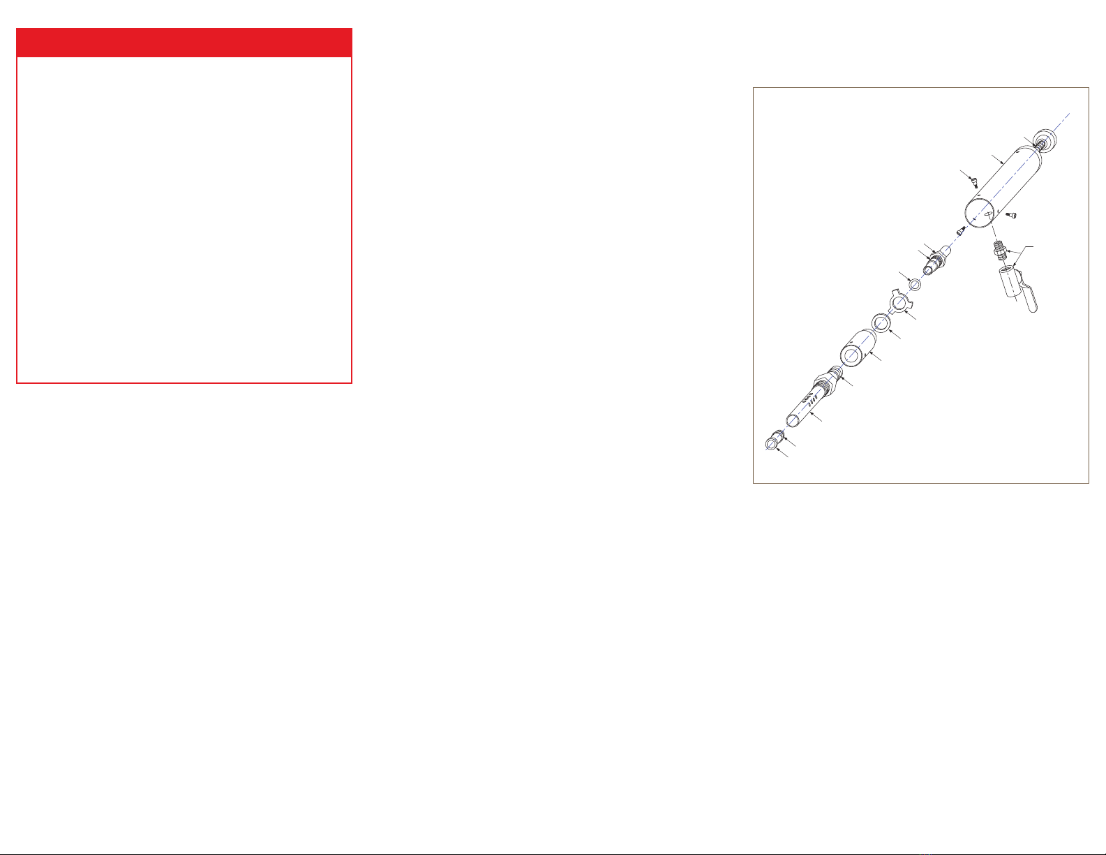
-015 size O-ring
Float
Float valve assembly
-020 size O-ring
Pump body
Rubber spacer
Centering ring
.002” and/or .003” shim(s)
-018 size O-ring
Hex barrel Ball valve and
pipe nipple
Shoulder screws
Cap assembly
Guide rod
generaL Safety cOnSiDeratiOnS
Warning: cOMpreSSeD air cOuLD cauSe Death,
bLinDneSS Or injury


