CONTENIDO DE LA CAJA
• Actuador
• Llave de utilidad *A
• Pilas alcalinas stilo
• El presente Folleto de instrucciones
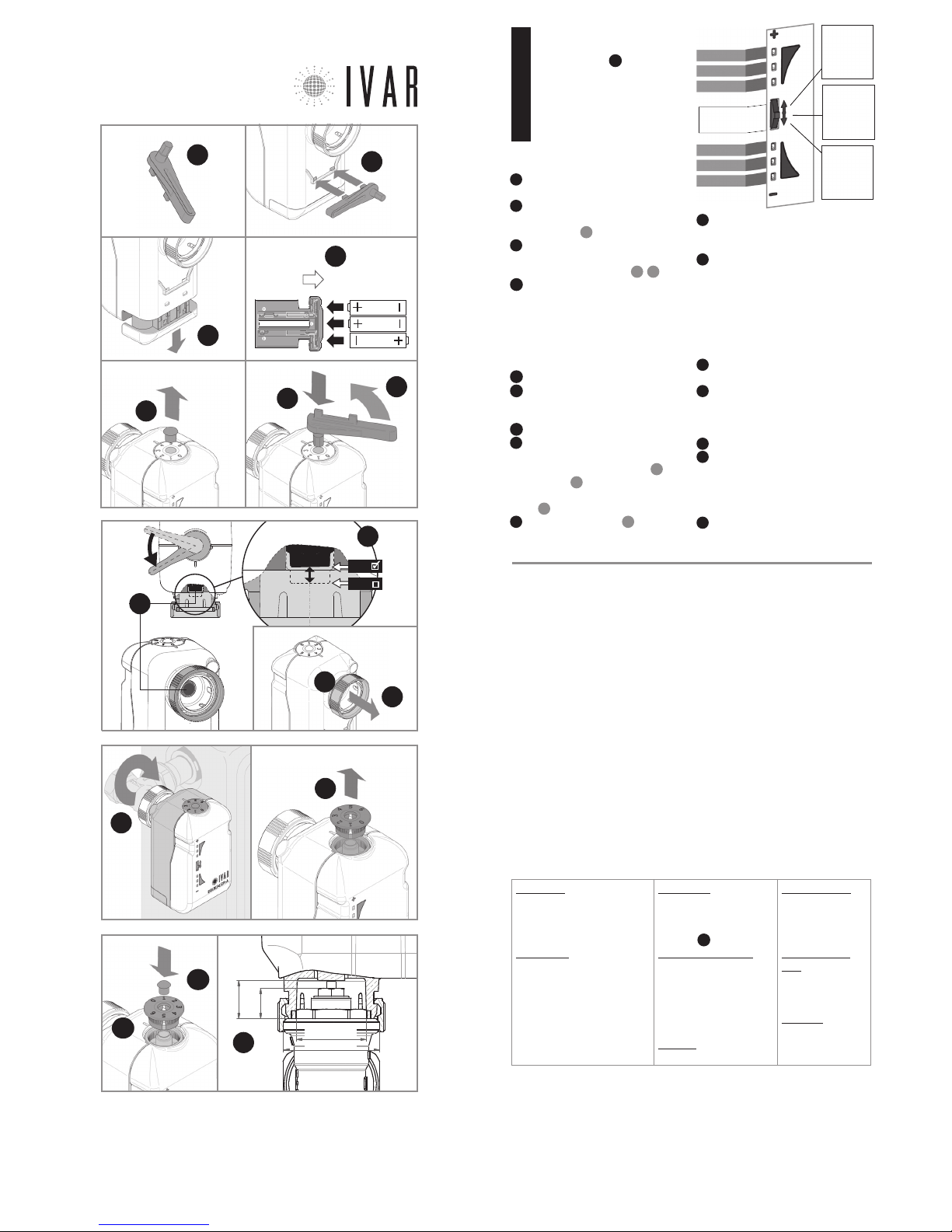
INSTALACIÓN/SUSTITUCIÓN DE
LAS PILAS
El actuador usa n. 3 pilas alcalinas AA
1,5V. Se deben colocar las pilas para
que el aparato funcione.
1Para sustituir las pilas usar la llave de
utilidad, que se suministra en la caja.
2Desbloquear la ranura de las pilas,
introduciendo la llave de utilidad como se
indica en la figura 2.
3
Quitar la ranura de alojamiento de las pilas y
colocar las pilas según el orden y el sentido indicado
en el fondo de la ranura; ver Figura
3
,
3A
.
4Reposicionar la ranura, desplazándola
completamente hasta que se dispare el
bloqueo. NOTA: VER EL MANUAL ADJUNTO AL
CRONOTERMOSTATO PARA COMPLETAR LA
INSTALACIÓN.
INSTALACIÓN DEL ACTUADOR
5
Asegurarse de haber colocado las pilas.
6Quitar (con un pequeño destornillador) el
perno de fijación del disco superior numerado
como se indica en la figura.
7
Presionar en el alojamiento la llave de utilidad.
8
Poner el actuador en apertura total, girando
lentamente la llave en sentido antihorario hasta
llegar a unos 45° del final de carrera
8A
, para
alinear el pistón
8C
con el punto de mínimo.
Dicho punto está indicado en la figura en el
detalle 8D. Después quitar la llave.
9Alzar el zuncho roscado 9A de conexión
en el sentido indicado.
10 Asegurar el actuador al radiador enros-
cando manualmente el zuncho roscado,
apretándolo con una llave adecuada.
11 Poner el actuador en cierre total, man-
teniendo el selector frontal del actuador en
posición ’-’ hasta el primer parpadeo del Led
4 (Ver figura arriba - MANDOS DEL ACTUADOR),
que se produce después de 5 segundos. Sol-
tar la tecla después de dicha señal. La inter-
mitencia rápida contemporánea de los Led 4,
5 y 6 indica que se ha realizado el cierre.
12 Quitar el disco numerado que está en la
parte superior del actuador (Ver figura).
13 Reposicionar el disco numerado, verifican-
do que el ‘0’ esté alineado con la muesca de
referencia (*); después presionar el disco en
su alojamiento.
14 Reposicionar el perno de fijación.
15
Para terminar la fase de cierre/apertura
asistida, es indispensable mantener el selector
en posición SELECCIONAR hasta que se iluminen
los Led 3 y 4, que se produce después de 5 se-
gundos. Después de dicha señal, soltar la tecla.
16 Realizar la asociación del actuador y la
verificación final (VER EL MANUAL ADJUNTO AL
CRONOTERMOSTATO).
ESPAÑOL
LED 1
LED 2
LED 3
LED 4
LED 5
LED 6
SELECTOR
FRONTAL
Posición
‘SELECCIO-
NAR’
PRESIONAR
MANDOS DEL
ACTUADOR Posición ‘+‘
EMPUJAR HA-
CIA ARRIBA
Posición ‘-‘
EMPUJAR
HACIA ABAJO
CARACTERÍSTICAS TÉCNICAS
TRANSMISIÓN
• frecuencia de transmisión:
915.00 MHz
• Capacidad de la señal: 33 yd en
ausencia de obstáculos
ALIMENTACIÓN
• Tensión: 4,5 V
• Tipo de baterías: n.3 pilas alcali-
nas estilo AA L(R6) 1,5V
• Autonomía: 3 años (con baterías
nuevas en buen estado y en condi-
ciones óptimas de funcionamiento) *
• Tipo de aparato: Electrónico digital
ACOPLAMIENTO
• Tipo de acoplamiento: M30x1,5
• Distancia de cierre X: com-
prendida entre 0.45 y 0.47 in;
ver Figura 17
CONDICIONES AMBIENTALES
• Límites de temperatura para el
transporte y el almacenamiento:
de -4 °F a +130 °F
• Límites de temperatura para el
funcionamiento:
de 23 °F a +110 °F
DIMENSIÓN
(in) L=3.60, H=1.90, W=2.60
CODIGO PRODUCTO
• Descripción:
Servomotor axial
•
EQUICALOR-A: Art. AS
1000 - Code 506364US
ALMACENAMIENTO
PILAS
• Temperatura: 68°F
garantizan la buena
duración de las pilas
SEGURIDAD
• Tipo de aislamiento:
CLASE III
CONDICIONES DE GARANTÍA
I.V.A.R. S.P.A está asegurada por daños ocasionados a terceros por defecto de fabricación constatado de los
productos, en los términos y límites enunciado en el Decreto Legislativo 206/2005. La cobertura máxima
de seguro de € 3.000.0000 por siniestro y por año. La responsabilidad de IVAR por los daños de productos
defectuosos está disciplinada por las condiciones generales de venta y por el decreto legislativo 206/05 (art
114-127) y se extiende por 2 años desde la instalación del producto. I.V.A.R. S.p.A. garantiza la conformidad
y el buen funcionamiento de sus productos en los términos citados por el decreto legislativo n. 206/05.
* La duración de la batería puede acortarse en caso de mala RADIO comunicación (L SIGN), en presen-
cia de obstáculos y en el caso de almacenamiento no conforme a las condiciones establecidas. Las
baterías de diferentes marcas pueden tener comportamientos y duración más corta de lo indicado.
F
CC ID: 2AB4Y506364US
Este dispositivo cumple con la parte 15 de las Nor-
mas de la FCC. El funcionamiento está sujeto a
estas dos condiciones: (1) este dispositivo no puede
producir interferencias perjudiciales (2) este dispo-
sitivo debe tolerar cualquier interferencia recibida,
incluidas aquellas interferencias que pueden provo-
car un funcionamiento no deseado.
NOTE: a partir de las pruebas a las que ha sido so-
metido este equipo, se concluye que cumple con
los límites para un dispositivo digital de Clase B, en
conformidad con la Parte 15 de las Normas de la
FCC. Estos límites están destinados a proporcionar
una protección razonable contra las interferencias
perjudiciales en una instalación de tipo residencial.
Este equipo genera, usa y puede emitir energía de
radiofrecuencias y, si no se instala y utiliza de acuer-
do con las instrucciones, puede provocar interferen-
cias perjudiciales en las comunicaciones vía radio.
Sin embargo, no puede garantizarse que no se pro-
duzcan interferencias en una instalación particular.
Si este equipo provoca una interferencia perjudicial
en la recepción de radio o televisión, que puede
estar determinada por su conexión o desconexión,
el usuario ha de intentar corregir la interferencia
aplicando una o varias de las siguientes medidas:
• Reorientar o reinstalar la antena receptora.
• Aumentar la distancia entre el equipo y el receptor.
• Conectar el equipo dentro o fuera de un circuito
diferente al que está conectado el receptor.
• Solicitar la ayuda del vendedor o de un técnico es-
pecializado en radio/TV.
Exposición a RF: este equipo cumple con los límites
de exposición a radiaciones establecidos por la FCC
para un ambiente no controlado. Este equipo debe
ser instalado y operado manteniendo una distancia
minima de 20 cm entre la persona y el elemento
transmisor. Este transmisor no debe estar situado
o funcionando simultáneament e con otra antena
o transmisor.
Advertencia: Las modificaciones o los cambios apli-
cados a este dispositivo que no hayan sido aproba-
dos expresamente por IVAR podrían anular la autori-
zación del usuario para utilizar el equipo.
CONTACTOS
IVAR US, Inc.
Dirección postal:
PO Box 8015, Elkridge, MD 21075
T: 1-855-9-IVAR-US
www.ivar-us.com
I.V.A.R. S.p.A.
Via IV Novembre, 181
25080 Prevalle (BS) - Italy
T: +39 030 68028 - F: +39 030 6801329
www.ivar-group.com
9
9A
FOLLETO DE INSTRUCCIONES AS1000
300538US-10-14
( X )
MAX=
0.37 in
MAX= Ø0.83 in
M30x1,5
10
12
8A
7
6
8D
OPEN
THIS WAY
3
MIN
MAX
8C
3A
17
2
*
13
14
*A