Wi-Fi Signal Booster
USER GUIDE
Technology
Thank you for purchasing the Ivation Wi-Fi Signal Booster. This User Guide is intended
to provide you with guidelines to ensure that operation of this product is safe and does
not pose risk to the user. Any use that does not conform to the guidelines described in
this User Guide may void the limited warranty.
Please read all the directions before using the product and retain this guide for reference.
This product is covered by a limited one year warranty. Coverage is subject to limits and
exclusions. See warranty for details.
Any changes or modifications to this device may void warranty.
Put an end to slow or spotty Wi-Fi. By enhancing signal speed and range, the Ivation
Wi-Fi Signal Booster can amplify your signal up to 20 times its original strength. It
works multi-directionally with any certified 802.11b/g/n Wi-Fi device.
Package Contents:
Wi-Fi booster base
9dbi omni antenna
Power adapter
User guide
FCC Compliance
FCC Statement and Declaration: Ivation declares that this device complies with Part 15 of the FCC Rules and Regulations. Operation of this device is subject
to the following two (2) conditions:
(1) This device may not cause harmful interference
(2) This device must accept any interference received, including interference that may cause undesired operation.
FCC Notice: This equipment has been tested and found to comply with the limits for a Class B digital device, pursuant to Par t 15 of the FCC Rules. These limit s
are designed to provide reasonable protection against harmful interference in a residential installation. This equipment generates, uses and can radiate radio
frequency energy and, if not installed and used in accordance with the instructions, may cause harmful interference to radio communications.
However, there is no guarantee that interference will not occur in a particular installation. If this equipment does cause harmful interference to radio or
television reception, which can be determined by turning the equipment off and on, the user is encouraged to try and correct the interference by one or more of
the following measures:
- Reorient or relocate the receiving antenna.
- Increase the distance between the equipment and the receiver.
- Connect the equipment to an outlet on a circuit different from that to which the receiver is connected.
- Consult the dealer or an experienced radio/ TV technician for help.
FCC Caution and Safety Notices: Any changes or modifications (including the antennas) made to this device that are not expressly approved by the
manufacturer may void the user’s authority to operate the equipment. This device and its antenna(s) must not be co-located or operating in conjunction with
any other antenna or transmitter. Avoid use of this product near water or during an electrical storm as there may be a remote risk of electrical shock from
lighting. This product may contain lead, known to the State of California to cause cancer, and birth defects or other reproductive harm. Wash hands after
handling. This device must always be used with a Listed Computer or device.
FCC Notice for Signal Amplifiers/Boosters: Signal Amplifiers and Boosters (such as this product) may only be used in a system in which it has obtained
authorization from the FCC. Signal Boosters (such as this product) may not be used with any device which has not obtained proper FCC authorization or has not
been cer tified for use as a system with the Signal Booster (such as this product.)
System Requirements:
• 802.11b, 802.11g or 802.11n certified wireless network/ wireless AP / router / PCI network adapter with a removable antenna
• Wireless device to connect to this unit
About Wireless Devices:
Any Wi-Fi device(802.11b/g) that use the IEEE802.11 wireless standard. These devices can range from wireless access points to wireless routers to
wireless PCI client cards.
About IEEE 802.11 Wireless Network Specifications:
802.11 applies to wireless LANs (Networks) and provides 1 or 2 Mbps transmission in the 2.4 GHz band using either frequency-hopping spread
spectrum (FHSS) or direct sequence spread spectrum (DSSS).
802.11b (also referred to as 802.11 High Rate or Wi-Fi) is an extension to 802.11 that applies to wireless LANs and provides 11 Mbps transmission
(with a fallback to 5.5, 2 and 1 Mbps) in the 2.4 GHz band. 802.11b uses only DSSS. The 802.11b spec was the 1999 ratification to the original 802.11
standard, allowing wireless functionality comparable to Ethernet.
802.11g applies to wireless LANs and provides 54 Mbps in the 2.4 GHz band. Backward compatible with IEEE 802.11b products.
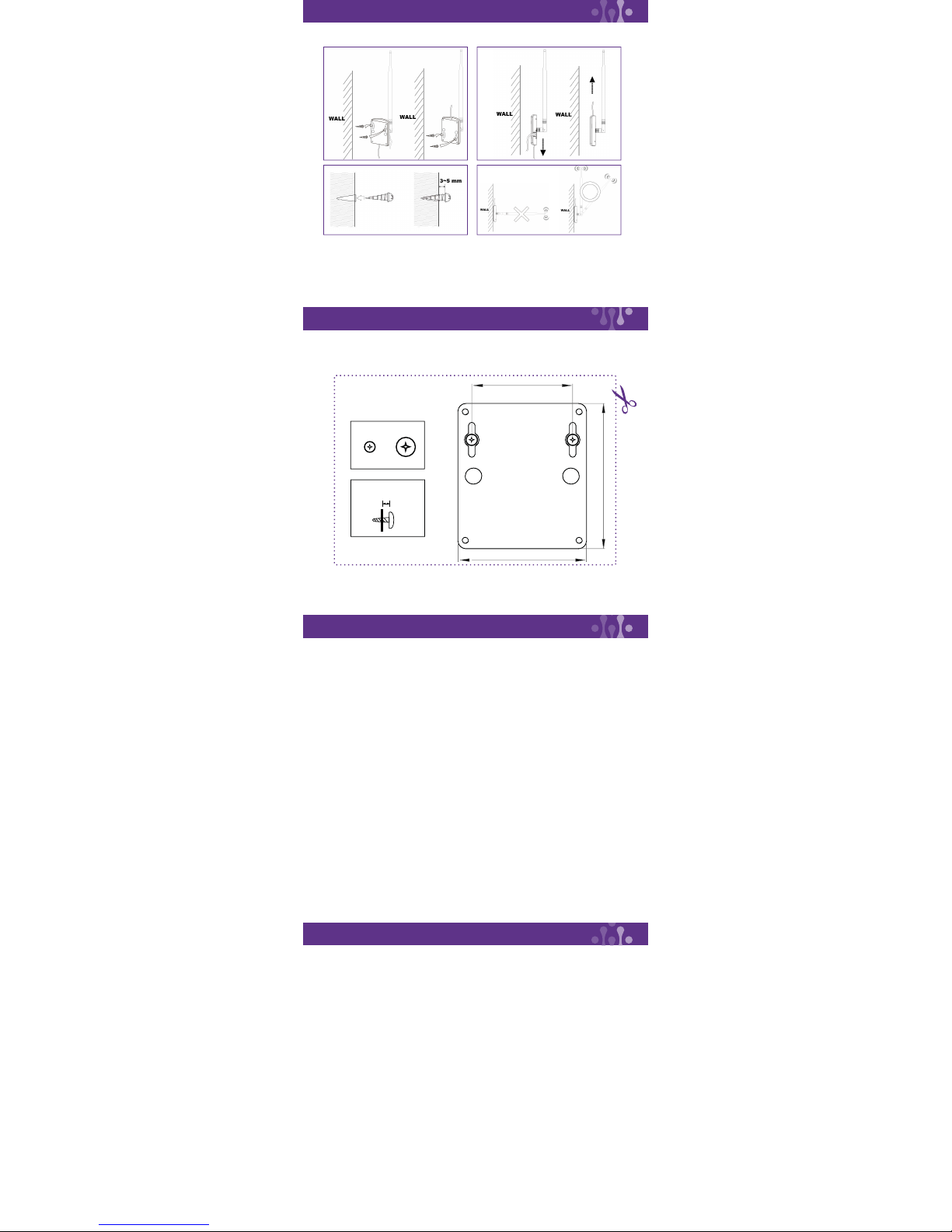
Attach the antenna to the base and locate it so you can get a better or higher position to receive or transmit signals when the antenna is connected
to an AP/AP router. Tilt or rotate the antenna for best results. The antenna can also be used with a PCI or USB adaptor equipped with an
SMA connector.
Hardware
Setup
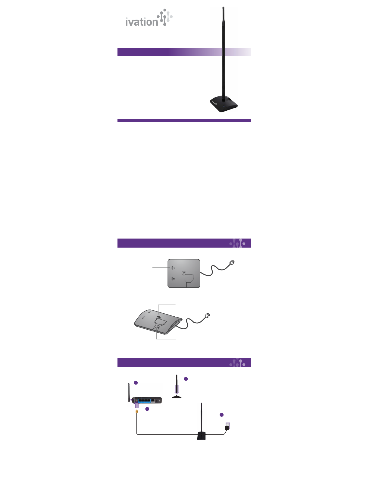
Detach the antenna from
your Certified Wireless Device
Attach the included
antenna to the base
of the signal booster
Plug in power adapter
Attach the signal booster to the
antenna connector of your
Wi-Fi device
Antenna Connector
Power Adapter DC Plug in
Connect to wireless
LAN devices
Front
Status LED:
Displays power and data
transmission status.
1
2
3
4
IVASB2000