manuals.online logo
Brands
  1. Home
  2. •
  3. Brands
  4. •
  5. iWire
  6. •
  7. Cables And Connectors
  8. •
  9. iWire DCCD Plug and Play Harness Kit User manual

iWire DCCD Plug and Play Harness Kit User manual

iWire DCCD Controller Plug and Play Kit Install Guide
1
This guide gives instructions on how to install the iWire Plug and Play Kit for a DCCD Controller.
DCCD Plug and Play Harness Kit
1. Transmission Adapter
2. DCCD Wiring Extension Harness
3. Ebake Harness
4. Throttle Position Sensor Harness
5. Ring Terminal for Ground
6. DCCD Jumper Pigtail
iWire DCCD Controller Plug and Play Kit Install Guide
2
The first step is to connect your DCCD Controller to the iWire Plug and Play Wiring Kit. To do this, you will connect the
DCCD Jumper Pigtail (item 6 in kit) to your DCCD Unit. Use the provided crimps and match color to color (example: crimp
blue to blue, red to red, green to green, etc.)
1. Strip wire on jumper and wire on DCCD Controller. Strip just enough to come a few millimetes from the outside edge
of the metal crimp.
2. Insert one end of the wire into the crimp and using a insultated or non-insulated guide, crimp the metal part of the
crimp. You will want to squeeze on the red line of the crimp.
iWire DCCD Controller Plug and Play Kit Install Guide
3
3. Repeat this step with the other end of the wire and crimp the other side of the crimp. It will look like this when both
sides are crimped. To test this crimp, gently pull on each side of the wire and make sure they do not come out of the
crimp.
4. Heat shrink the clear plastic ends of the crimp onto the wire to secure it into place.
iWire DCCD Controller Plug and Play Kit Install Guide
4
5. Repeat this process for all wires. Make sure to match color to color (example: brown to brown, blue to blue, etc).
iWire DCCD Controller Plug and Play Kit Install Guide
5
Next mount the DCCD control box into the car. We recommend the transmission tunnel on the passenger’s side or
behind the center console. Any location that seems suitable will also be fine.
Next make a couple of simple connections:
1. Connect the iWire transmission adapter (item 1 in kit) to both the new transmission and the stock harness. These
plugs are located in the engine bay near the transmission.
DCCD transmission side (6 pin plug) will plug into the new DCCD equipped transmission. (picture below)
The bulkhead side of the transmission adapter connector plugged in. This will plug into the old transmission wiring. It
should be either a single 4 pin plug or two 2 pin plugs. Leave the 3 pin Deutsch connector open for now.
iWire DCCD Controller Plug and Play Kit Install Guide
6
Another view of the connector to the body harness to transmission adapter harness connection
iWire DCCD Controller Plug and Play Kit Install Guide
7
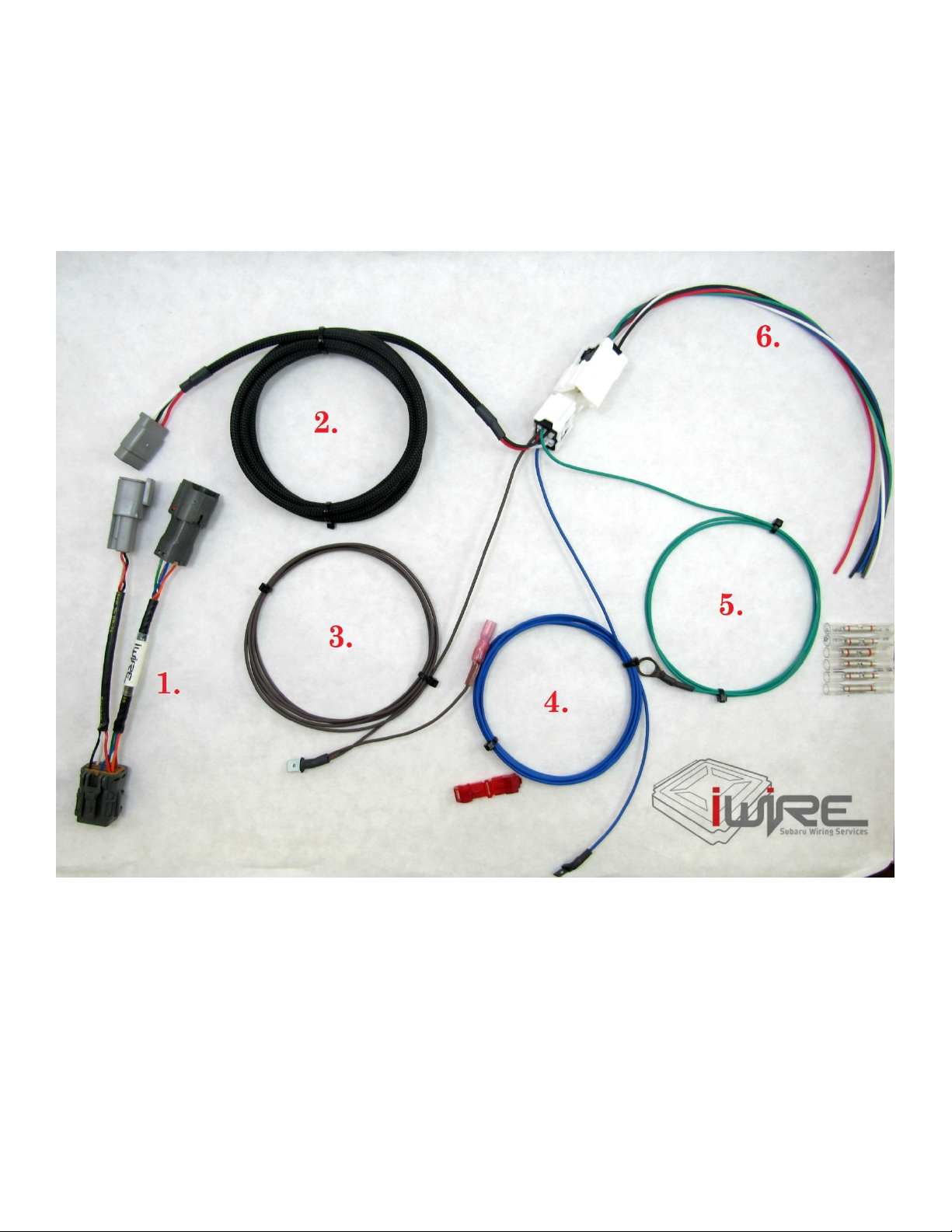
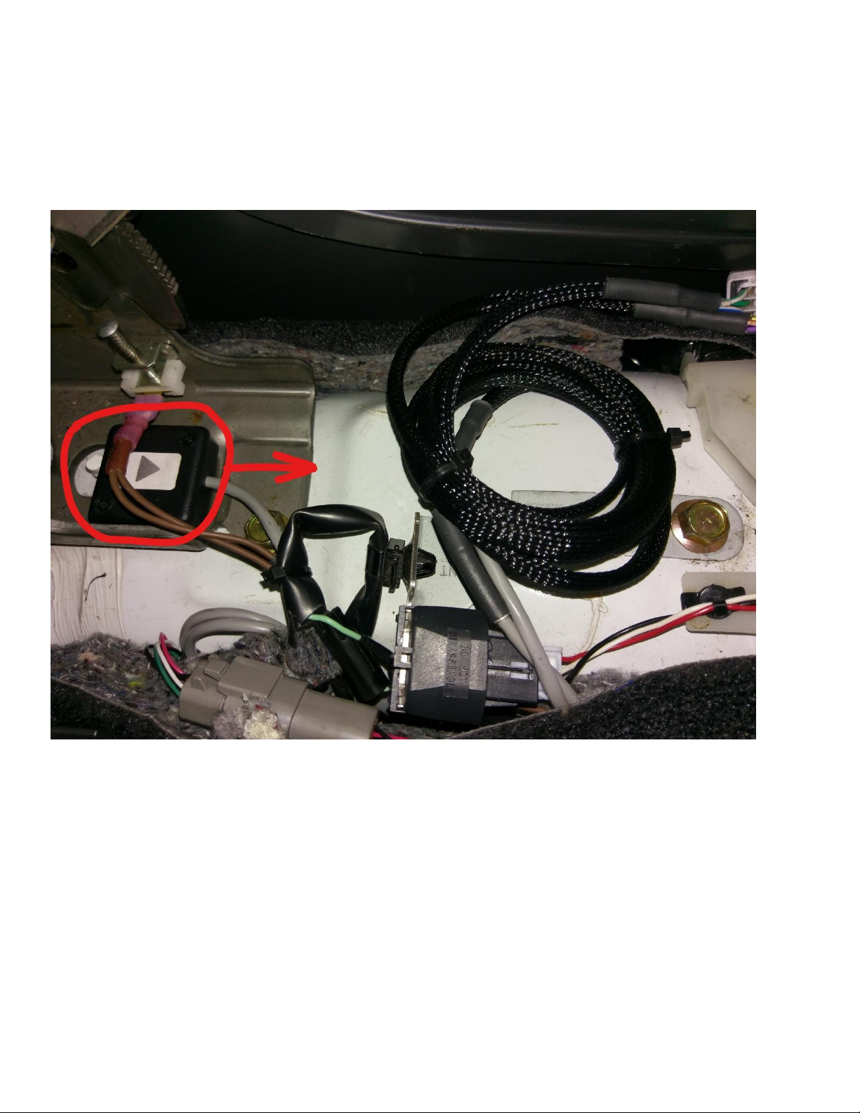
2. Take the DCCD Wiring Extension Harness (black sleeved wires –item 2 in kit) and route those wires from inside the
cabin to the engine bay. We suggest using the passenger side firewall grommet. Make a small hole in the grommet with
a razor blade just big enough to allow wires through the grommet (this is why we depin the connector). Put the side with
the three terminals through the grommet and into the engine bay.
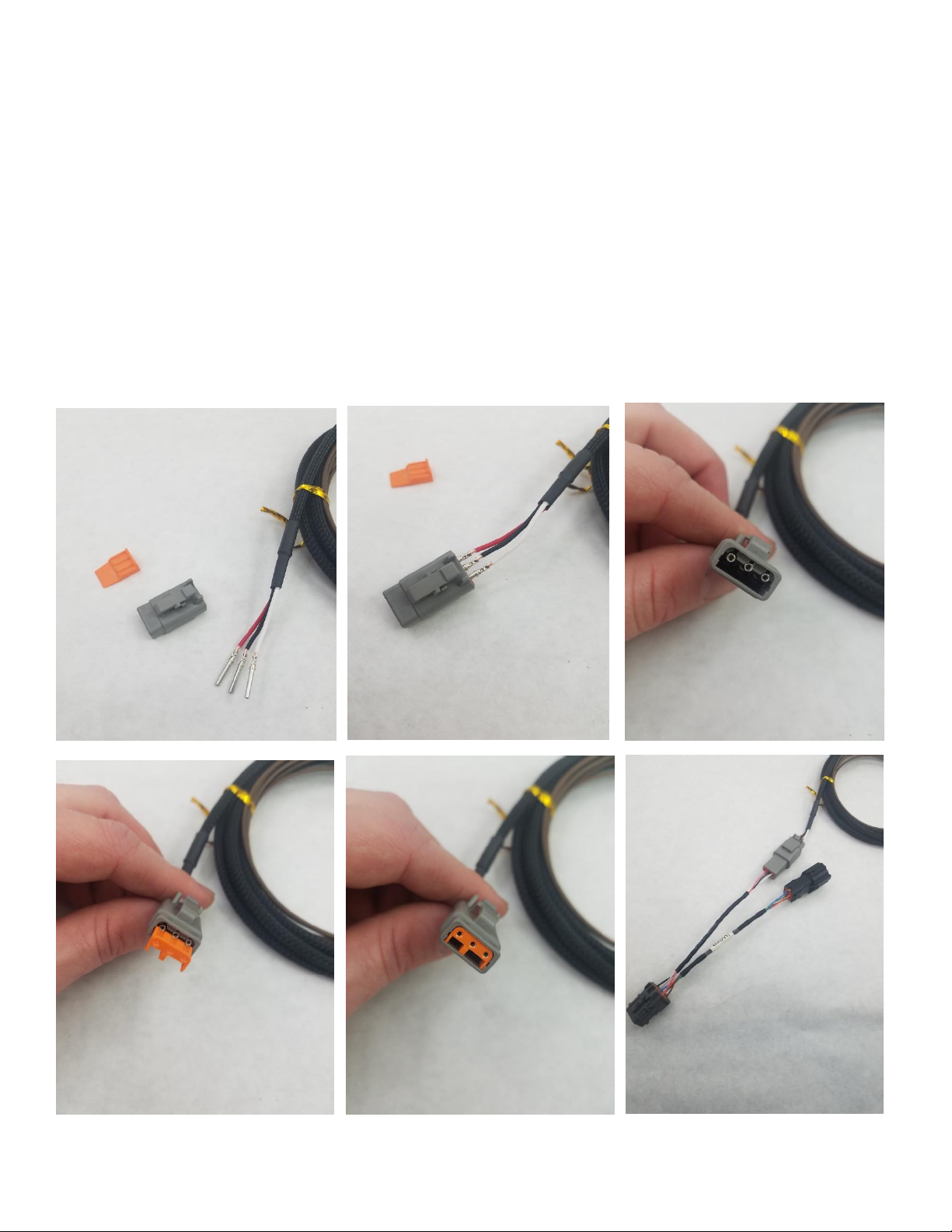
Once through the firewall, run the Black, White, and Red wires to the transmission and insert them into the 3-pin
connector provided in the kit matching White to White, Black to Black, and Red to Red. There is a small number on each
side of the plug which will help distinguish the pin order. Pin 1 is White, Pin 2 is Black, and Pin 3 is Red. Pull gently on the
wires to make sure they are locked. Insert Orange lock. Connect this plug to the matching Grey 3 pin connector on the
transmission adapter harness already installed in the engine bay.
Connect the White 6 pin plug on the other end of this extension harness into the matching 6 pin receptacle on the
DCCDPro unit.
iWire DCCD Controller Plug and Play Kit Install Guide
8
3. Install the Ebrake jumper harness (brown wire –item 3 in kit). We suggest routing this wire through the center tunnel
below the shifter trim to the Ebrake location. Take out the upper trim pieces of the center console and route it along the
carpet. Make sure the wires do not get pinched or sandwiched here.
iWire DCCD Controller Plug and Play Kit Install Guide
9
4. Mount the G Sensor Unit. Route these wires the same way as the Ebrake. Mount the G Sensor Unit in the center of
the car, equal distance from the front and rear. To attach it inside the center console, use an epoxy or a small piece of
double sided tape like 3M Tape. Make sure to mount it so the arrow sticker is facing the front of the car.
iWire DCCD Controller Plug and Play Kit Install Guide
10
5. Ground the ring terminal from the Green wire (item 5 in kit). This ground terminal can go to any bolt in the car. We
suggest routing it to either the bolt that holds the G Sensor below the Ebrake or a bolt on the dash bar. Please note –if
there is paint on this bolt you will need to sand it for better contact. You want metal to metal contact here for the best
ground possibl.e
iWire DCCD Controller Plug and Play Kit Install Guide
11
6. Tap the Throttle Position Sensor Wire (Blue wire –item 4 in kit). This step is for DCCDPro Spiider controllers only. If
you have a Manual controller you will not complete this step.
First pull back the carpet in the passenger side footwell. Then unbolt the metal kickplate. This will reveal the ECU. For
which wire to tap, see below for the information that matches your car.
For 2002-2005 WRX - Tap into the Light Green wire on the top row of this B plug in the ECU. Make sure not to cut or
damage the TPS wire during this process.
For 2006-2007 WRX and 2007 STi –Tap into the White wire on this plug, A 18 for throttle position input at the ECU.
iWire DCCD Controller Plug and Play Kit Install Guide
12
For 2004-2006 STI and 2004-2005 FXT - Tap into the Red with Blue Stripe wire into the wire in this plug, C18 for TPS
input. Make sure not to cut or damage the TPS wire during this process.
For Baja Turbo - Tap into the White wire into the wire in this plug, C18 for TPS input. Make sure not to cut or damage
the TPS wire during this process. (in picture shows red wire with blue stripe but this is location of where white wire will
be).
iWire DCCD Controller Plug and Play Kit Install Guide
13
For V1 to V3 –Tap the Light Green wire on Pin 20 in the yellow plug for throttle position at the engine computer.
For V5 to V6 RHD –Tap into the Light Green wire on pin 20 in th Blue plug for throttle position at the engine computer.
iWire DCCD Controller Plug and Play Kit Install Guide
14
Once you have figured out which wire to tap, place Red T tap provided in the kit onto the wire and squeeze initially with
fingers, then clamp closed with a pair of pliers. (the pictures below are from a 2002-2005 WRX and the color of the plug
may change.)
iWire DCCD Controller Plug and Play Kit Install Guide
15
Make sure T tap clamp is locked and secure, then insert Blue spade terminal into T tap.
Once TPS wire and Blue wire are clamped together, Route the Blue wire under the kick plate before reinstalling it. We
suggest zip tying the excess length for a cleaner install. Reinstall the kick plate and passenger side carpeting.
iWire DCCD Controller Plug and Play Kit Install Guide
16
6. Test DCCDPro is working. There are a few tests to run to ensure the install is complete.
A. If you have a DCCDPro Spiider, it will always default to auto mode when the car turns off and back on. So to test this,
turn the car off and back on. If you have a Spiider with Cluster Output, you should see the light scroll either on the dash
or on the LED light strip. If you have a Spiider without Cluster Output, you should see the light on the auto/manual
button get brighter and dimmer. (please note: if using an old auto/manual button, the light can burn out).
B. For all DCCDPro Controllers - make sure the Ebrake is down (the unit will not work if the Ebrake is up) and put the
DCCDPro into manual mode. Scroll with the switches and see if that is working.
C. If the above looks good it’s time to do a quick road test. Take the car to a parking lot. Make a super slow, tight turn
with the DCCDPro in manual mode and open mode. Slowly scroll it from open toward lock, as you do that you will feel
the center diff start to engage and the car wil hop as you make the turn because the DCCDPro is not allowing the wheels
to slip. Then roll it back to open and see if it opens back up.
Congratulations! Your iWire Plug and Play Kit for DCCD Controller is installed!
If you have any questions during your install please check out our DCCD Trouble Shooting Guide found on our Tech Docs
page on our website or call/email us with any questions.

Popular Cables And Connectors manuals by other brands

Mophie powerstation plus XL user manual

Mophie

Mophie powerstation plus XL user manual

ABB FlexPendant product manual

ABB

ABB FlexPendant product manual

id-Technik K-Tower Series Assembly instructions

id-Technik

id-Technik K-Tower Series Assembly instructions

Belden ELWIKA 5012 PG9 Assembly instructions

Belden

Belden ELWIKA 5012 PG9 Assembly instructions

Signat Platinum S104105 Brochure & specs

Signat

Signat Platinum S104105 Brochure & specs

Festo NEBM­S1G9-E-Q5-LE6 Series Assembly instructions

Festo

Festo NEBM­S1G9-E-Q5-LE6 Series Assembly instructions

Vanco Evolution EVSLIM12 manual

Vanco

Vanco Evolution EVSLIM12 manual

Philips SWV3133W Specifications

Philips

Philips SWV3133W Specifications

Philips SWX1237 Specifications

Philips

Philips SWX1237 Specifications

Cypress CDVI-8 Operation manuals

Cypress

Cypress CDVI-8 Operation manuals

Philips SWV3435W Specification sheet

Philips

Philips SWV3435W Specification sheet

Alesis GuitarLink Wireless quick start guide

Alesis

Alesis GuitarLink Wireless quick start guide

Fujikura FSM-70S Help guide

Fujikura

Fujikura FSM-70S Help guide

DREXAN CMH-CON installation instructions

DREXAN

DREXAN CMH-CON installation instructions

VIVIFY ARQUUS W73 manual

VIVIFY

VIVIFY ARQUUS W73 manual

Kidde Alarmline II Analogue installation instructions

Kidde

Kidde Alarmline II Analogue installation instructions

Siemens SIMATIC NET IE FC RJ45 Compact operating instructions

Siemens

Siemens SIMATIC NET IE FC RJ45 Compact operating instructions

Hilti S-BT-ER Installation instruction

Hilti

Hilti S-BT-ER Installation instruction

manuals.online logo
manuals.online logoBrands
  • About & Mission
  • Contact us
  • Privacy Policy
  • Terms and Conditions

Copyright 2025 Manuals.Online. All Rights Reserved.