iWorX TS300 Series User manual

© 2010 Taco Electronic Solutions, Inc. 1
Installation Guide 502-017
TS300 Series Sensors
SUPERSEDES: October 22, 2010 EFFECTIVE: November 17, 2010
Plant ID: 001-3945
Table of Contents
TS300 Series Sensors . . . . . . . . . . . . . . . . . . . . . . . . . 2
Overview . . . . . . . . . . . . . . . . . . . . . . . . . . . . . . . . . 2
Features. . . . . . . . . . . . . . . . . . . . . . . . . . . . . . . . . . 2
Applicable Documentation . . . . . . . . . . . . . . . . . . . . 2
Typical Use . . . . . . . . . . . . . . . . . . . . . . . . . . . . . . . 3
Representations and Warranties . . . . . . . . . . . . . . . . . 3
Installation Instructions. . . . . . . . . . . . . . . . . . . . . . . . . 3
Precautions . . . . . . . . . . . . . . . . . . . . . . . . . . . . . . . . . 3
General . . . . . . . . . . . . . . . . . . . . . . . . . . . . . . . . . . 3
Static Electricity . . . . . . . . . . . . . . . . . . . . . . . . . . . . 4
Location . . . . . . . . . . . . . . . . . . . . . . . . . . . . . . . . . . 4
FCC Compliance . . . . . . . . . . . . . . . . . . . . . . . . . . . 4
Canadian Department of Communications . . . . . . . 4
Before Installing . . . . . . . . . . . . . . . . . . . . . . . . . . . . . . 5
About this Document . . . . . . . . . . . . . . . . . . . . . . . . 5
Inspecting the Equipment . . . . . . . . . . . . . . . . . . . . 5
What is Not Included with this Equipment . . . . . . . . 5
Installation . . . . . . . . . . . . . . . . . . . . . . . . . . . . . . . . . . 5
Mounting the Device . . . . . . . . . . . . . . . . . . . . . . . . 5
Wiring Information . . . . . . . . . . . . . . . . . . . . . . . . . . . 10
Communications Wiring. . . . . . . . . . . . . . . . . . . . . 10
Features . . . . . . . . . . . . . . . . . . . . . . . . . . . . . . . . . . . 12
Sensor Operation Diagnostics . . . . . . . . . . . . . . . .12
Display Screen Functions. . . . . . . . . . . . . . . . . . . .14
Fan Functions. . . . . . . . . . . . . . . . . . . . . . . . . . . . .14
General Functions . . . . . . . . . . . . . . . . . . . . . . . . .14
Mode Functions . . . . . . . . . . . . . . . . . . . . . . . . . . .14
Override Functions . . . . . . . . . . . . . . . . . . . . . . . . .15
Service Pin . . . . . . . . . . . . . . . . . . . . . . . . . . . . . . .15
Setpoint Functions . . . . . . . . . . . . . . . . . . . . . . . . .15
Specifications . . . . . . . . . . . . . . . . . . . . . . . . . . . . . . . 17
Sensors . . . . . . . . . . . . . . . . . . . . . . . . . . . . . . . . .17
General. . . . . . . . . . . . . . . . . . . . . . . . . . . . . . . . . .17
Software . . . . . . . . . . . . . . . . . . . . . . . . . . . . . . . . .18
Communications. . . . . . . . . . . . . . . . . . . . . . . . . . .18
Troubleshooting . . . . . . . . . . . . . . . . . . . . . . . . . . . . . 19

iWorX® TS300 Series Sensor
2 502-017, Effective: November 17, 2010
© 2010 Taco Electronic Solutions, Inc.
TS300 SERIES SENSORS
iWorX® TS300 Series Sensors are a family of wall-mounted digital temperature and humidity sensors for use with
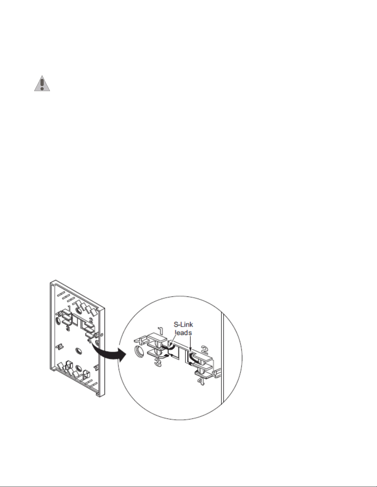
iWorX® HVAC Controllers. These sensors feature a Sensor Link (S-Link) communication protocol which provides a
simple two-wire interface for power and exchange of sensor and control information. Control information includes occu-
pancy override selection, heat/cool status, temperature setpoints, and fan mode.
Overview
Available in six models, these iWorX® TS300 Series Sensors provide integral analog to digital conversion for elimina-
tion of noise effects and wire resistance offset between sensor and controller.
Using the digital wall sensor, the operator can monitor performance and edit operational settings.
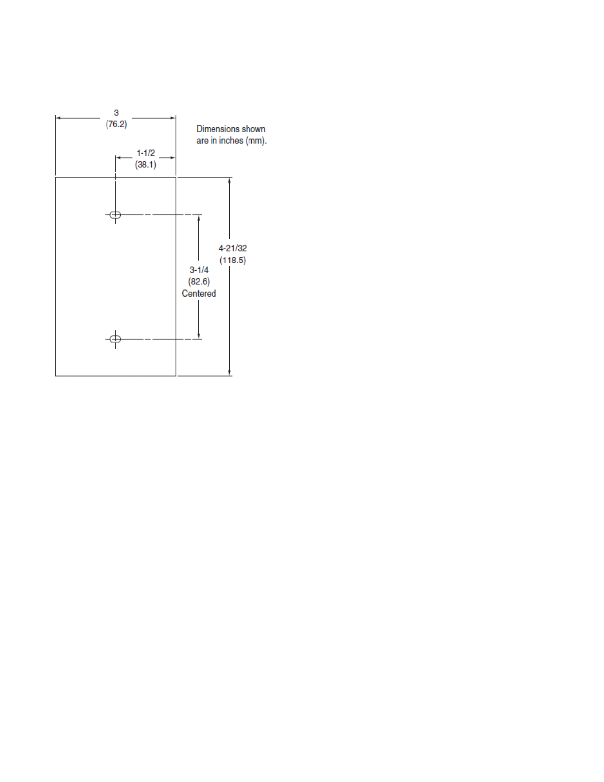
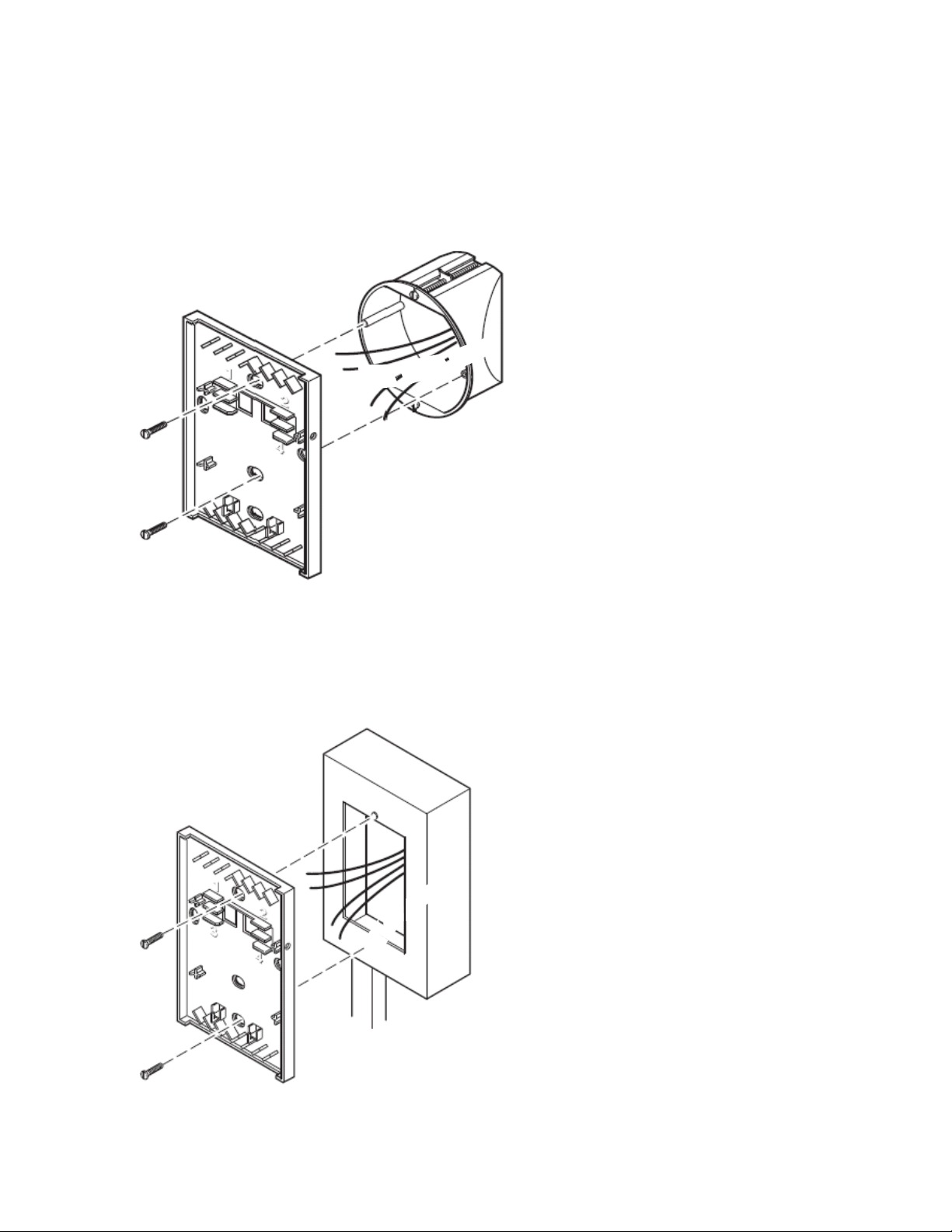
iWorX® TS300 Series Sensors are suitable for direct-wall, 2 x 4 electrical box, 1/4 DIN electrical box, or surface box
mounting.
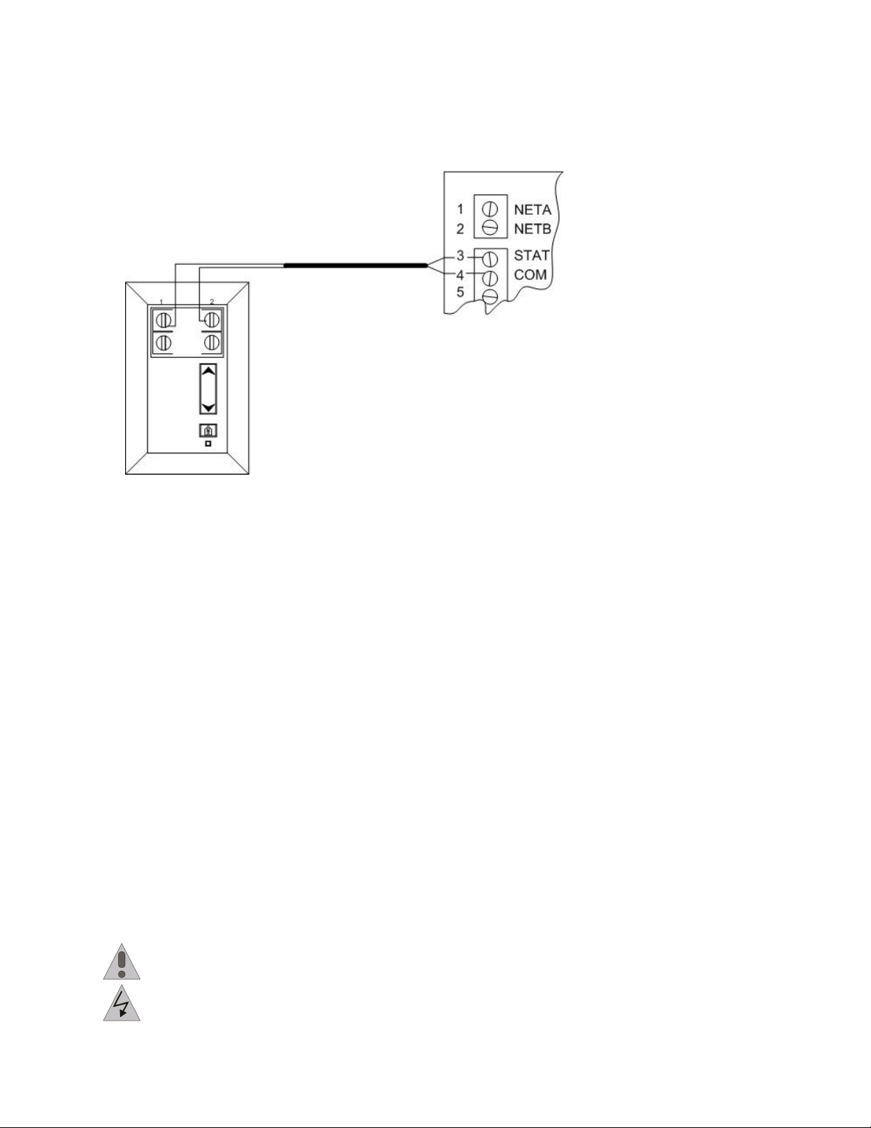
The TS300 series sensor measures room conditions and transmits the information to the controller via the S-Link. A
single sensor is connected directly to an application-specific iWorX® Series controller via low-cost, unshielded, twisted
pair cable. The connection between the sensor and controller is not polarity-sensitive.
Features
• Contemporary, low-profile packaging.
• Digital zone temperature indication (selectable for 0.1 or 1 degree display resolution of °F or °C).
• Self-compensating temperature conversions remove the need to calibrate over time.
• Digital zone humidity indication (selectable for 0.1 or 1% RH display resolution).
• Long-life humidity sensing element with excellent resistance to contamination and condensation.
• Pushbutton override capabilities allow occupants to switch to timed occupied mode for after hours operation.
• Displays selected system values such as setpoints, and operating mode.
• Directly connects to selected iWorX® controllers via low-cost, unshielded, twisted-pair cable, which provides both
power and communication.
• Separate wiring subbase and electronics.
Applicable Documentation
Description Audience Purpose
iWorX® TS300 Series Sensors
Installation Guide, Document No.
502-017 (this document)
– Application Engineers
– Wholesalers
– Contractors
Provides specific application information about the sensors,
including mounting, wiring, and operating instructions.
iWorX® Sensor Compatibility, Doc-
ument No. 509-001
– Application Engineers
– Wholesalers
– Contractors
Shows operational compatibility among the various iWorX®
sensors and controllers.
iWorX® LCI2 Application Guide,
Document No. 505-002
– Application Engineers
– Installers, End users
– Service Personnel
– Start-up Technicians
Provides instructions for setting up and using the iWorX®
Local Control Interface.
http://iWorxWizard.taco-hvac.com – Application Engineers
– Wholesalers
– Contractors
An on-line configuration and submittal package generator
based on user input. Automatically generates bill of materi-
als, sequence of operations, flow diagrams, wiring diagrams,
points and specifications.
Additional Documentation LonWorks FTT-10A Free Topology Transceiver User’s Guide, published by Echelon Cor-
poration. It provides specifications and user instructions for the FTT-10A Free Topology
Transceiver. Information is also available at the following web site: www.echelon.com/sup-
port/documentation/manuals/transceivers.

iWorX® TS300 Series Sensor
502-017, Effective: November 17, 2010 3
© 2010 Taco Electronic Solutions, Inc.
Typical Use
Figure 1: Typical use diagram for an iWorX® TS300 Series Sensor.
REPRESENTATIONS AND WARRANTIES
This Document is subject to change from time to time at the sole discretion of Taco Electronic Solutions, Inc. All
updates to the Document are available at www.taco-hvac.com. When installing this product, it is the reader’s responsi-
bility to ensure that the latest version of the Document is being used.
The iWorX® Sensor shall only be used for the applications identified in the product specifications and for no other pur-
poses. For example, the iWorX® Sensor is not intended for use to support fire suppression systems, life support sys-
tems, critical care applications, commercial aviation, nuclear facilities or any other applications where product failure
could lead to injury to person, loss of life, or catastrophic property damage and should not be used for such purposes.
Taco Electronic Solutions, Inc. will not be responsible for any product or part not installed or operated in conformity with
the Document and instructions or which has been subject to accident, disaster, neglect, misuse, misapplication, inade-
quate operating environment, repair, attempted repair, modification or alteration, or other abuse. For further informa-
tion, please refer to the last page of this Document for the company’s Limited Warranty Statement, which is also issued
with the product or available at www.taco-hvac.com.
INSTALLATION INSTRUCTIONS
PRECAUTIONS
General
This symbol is intended to alert the user to the presence of important installation and maintenance (servic-
ing) instructions in the literature accompanying the equipment.
WARNING: Electrical shock hazard. Disconnect ALL power sources when installing or servicing this
equipment to prevent electrical shock or equipment damage.

iWorX® TS300 Series Sensor
4 502-017, Effective: November 17, 2010
© 2010 Taco Electronic Solutions, Inc.
Make all wiring connections in accordance with these instructions and in accordance with pertinent national and local
electrical codes.
Static Electricity
Static charges produce voltages that can damage this equipment. Follow these static electricity precautions when
handing this equipment.
• Work in a static free area.
• Touch a known, securely grounded object to discharge any charge you may have accumulated.
• Use a wrist strap when handling printed circuit boards. The strap must be secured to earth ground.
Location
Avoid locations where corrosive fumes, excessive moisture, vibration or explosive vapors are present.
Avoid electrical noise interference. Do not install near large contactors, electrical machinery, or welding equipment.
This equipment is suitable for indoor use only. Operate where ambient temperatures do not exceed 122 °F (50 °C) or
fall below 32 °F (0 °C) and relative humidity does not fall below 5% or exceed 95%, non-condensing.
The humidity sensing element of TS302, TS304 and TS306 models will recover from short term exposure to liquid
water or condensation. Repeated exposure will degrade the performance of the sensor.
Locate the sensor on an inside wall where the sensor is exposed to at least 30 feet (9 meters) per minute of unre-
stricted air circulation. The location should represent the average temperature in the room or space. Make certain sen-
sor is located out of direct sunlight, away from sources of heat or cold, and away from concealed ducts or pipes.
FCC Compliance
This equipment has been tested and found to comply with the limits for a Class B digital device, pursuant to Part 15 of
the FCC rules. These limits are designed to provide reasonable protection against harmful interference. This equip-
ment can radiate radio frequency energy and, if not installed and used in accordance with the instructions, may cause
harmful interference to radio communications. However, there is no guarantee that interference will not occur in a par-
ticular installation. If this equipment does cause harmful interference to radio or television reception, which can be
determined by turning the equipment off and on, the user is encouraged to try to correct the interference by one or
more of the following measures:
• Reorient or relocate the receiving antenna.
• Increase the separation between the equipment and the receiver.
• Connect the equipment to a power source different from that to which the receiver is connected.
• Consult the equipment supplier or an experienced radio/TV technician for help.
You are cautioned that any changes or modifications to this equipment not expressly approved in these instructions
could void your authority to operate this equipment in the United States.
Canadian Department of Communications
This Class B digital apparatus meets all requirements of the Canadian Interference-Causing Equipment Regulations.

iWorX® TS300 Series Sensor
502-017, Effective: November 17, 2010 5
© 2010 Taco Electronic Solutions, Inc.
BEFORE INSTALLING
About this Document
The instructions in this manual are for the TS300 series sensor, which provides temperature and (optional) humidity
sensing capabilities to an iWorX® system.
Inspecting the Equipment
Inspect the shipping carton for damage. If damaged, notify the carrier immediately. Inspect the equipment for damage.
Return damaged equipment to the supplier.
The TS300 Series sensor is packaged disassembled in one box and consists of three major parts:
• A pre-wirable base plate for wiring to the controller S-Link connections
• An electronic assembly containing the sensors and associated circuitry
• A removable cover
What is Not Included with this Equipment
• Job wiring diagrams
• Tools:
– Drill and bits for mounting screws
– Level
– Static protection wrist strap
• Two mounting screws (dry-wall anchors for direct-wall mount)
• Accessories
INSTALLATION
Warning: Electrical shock hazard. To prevent electrical shock or equipment damage, disconnect ALL
power sources to controllers and loads before installing or servicing this equipment or modifying any wir-
ing.
Mounting the Device
iWorX® TS300 Series sensors can be direct-wall, 2 x 4 electrical box, 1/4 DIN electrical box, or surface box mounted.
See Figure 2 and Figure 3 for appropriate mounting dimensions.

iWorX® TS300 Series Sensor
6 502-017, Effective: November 17, 2010
© 2010 Taco Electronic Solutions, Inc.
Figure 2: LEFT: Mounting Dimensions for Direct-wall, 2 x 4 Electrical Box, and Surface Box Mounting.

iWorX® TS300 Series Sensor
502-017, Effective: November 17, 2010 7
© 2010 Taco Electronic Solutions, Inc.
Figure 3: Mounting Dimensions for 1/4 DIN Electrical Box Mounting.

iWorX® TS300 Series Sensor
8 502-017, Effective: November 17, 2010
© 2010 Taco Electronic Solutions, Inc.
Direct-wall Mount
1.Use mounting dimensions shown in Figure 2.
2.Feed S-Link wires through base plate.
3.Using two appropriate screws (use drywall anchors as necessary), mount base plate to wall (shown below).
Figure 4: Direct Wall Mount.
2 x 4 Electrical Box Mount
1.Use mounting dimensions shown in Figure 2.
2.Feed S-Link wires from electrical box through base plate.
3.Using two 6-32 x 5/8 in. flat head screws (not provided), mount base plate to electrical box (shown below).
Figure 5: 2 x 4 Electrical Box Mount.

iWorX® TS300 Series Sensor
502-017, Effective: November 17, 2010 9
© 2010 Taco Electronic Solutions, Inc.
1/4 DIN Electrical Box Mount
1.Use mounting dimensions shown in Figure 3.
2.Feed S-Link wires from electrical box through base plate.
3.Using two appropriate screws (not provided), mount base plate to electrical box using vertical mounting holes
indicated in the figure below.
Figure 6: 1/4 DIN Electrical Box Mount.
Surface Box Mount
1.Use mounting dimensions shown in Figure 2.
2.Feed S-Link wires from electrical box through base plate.
3.Using two 6-32 x 5/8 in. flat head screws (not provided), mount base plate to surface box (see figure below).
Figure 7: Surface Box Mount.

iWorX® TS300 Series Sensor
10 502-017, Effective: November 17, 2010
© 2010 Taco Electronic Solutions, Inc.
WIRING INFORMATION
The following electrical connection can be made to the iWorX® TS300 series sensors:
• Sensor Link (S-Link) Wiring
CAUTION: Do not connect any power wiring to the sensor. Failure to observe this precaution will damage
the sensor.
Communications Wiring
Communications wiring includes a connection between an iWorX® controller and an iWorX®TS300 Series sensor via
the S-Link.
Sensor Link (S-Link) Wiring
S-Link wiring powers and enables the TS300 sensor. The S-Link needs at least 24 gauge (0.205 mm2), twisted pair,
voice grade telephone wire. The capacitance between conductors cannot be more than 32 pF per foot (0.3 m). If
shielded cable is used, the capacitance between any one conductor and the others, connected to the shield, cannot be
more than 60 pF per foot (0.3m). Maximum wire length is 200 ft. (61 m).
Note:
• S-Link wiring is polarity insensitive.
• Shielded cable is not required for S-Link wiring.
• S-Link wiring can be in the same conduit with UI, AO, and DI Wiring.
• S-Link wiring must be dedicated to S-Link communications. It cannot be part of an active, bundled telephone trunk.
• If the cable is installed in areas of high RIF/EMI, the cable must be in conduit.
Connect the iWorX® TS300 Series Sensor
1.Strip 1/4 in. (6mm) of insulation from S-Link wires.
2.Connect wires to screw terminals 1 and 2 (Figure 8). The S-Link terminals are polarity insensitive.
3.Push excess wire back through the base plate to minimize air flow restriction.
Figure 8: S-Link Connections.

iWorX® TS300 Series Sensor
502-017, Effective: November 17, 2010 11
© 2010 Taco Electronic Solutions, Inc.
Wiring Checkout
Verify wiring between TS300 sensor base plate and the iWorX® Controller is installed according to job wiring dia-
gram, national and local wiring codes.
Electronic Assembly and Cover Installation
1.Set electronic assembly onto bottom hooks of base plate.
2.Secure electronic assembly to base plate by tightening two screws at top of assembly (Figure 9).
CAUTION:
•Observe static precautions when handling electronic assemblies.
•Handle electronic assemblies with care to prevent damage to the temperature and humidly sensing ele-
ments.
•Do not touch humidity sensing element on the TS302, TS304, and TS306 models. The element is located
beneath a small plastic housing on the back of the electronic assembly.
•Failure to observe these precautions can damage the sensor.
3.Insert bottom tabs of cover and then snap top into place.
Figure 9: Electronic Assembly Installation.
Note: To remove sensor cover, place thumb in middle of sensor, grasp top edge of cover with fingers and
pull firmly.

iWorX® TS300 Series Sensor
12 502-017, Effective: November 17, 2010
© 2010 Taco Electronic Solutions, Inc.
FEATURES
Table 1: Model and Feature Comparison
Sensor Operation Diagnostics
In the Diagnostics Mode, the sensor times out and returns to the default screen if left idle for forty seconds. Subnet
Address, Node Address, Alarms, and Errors are view-only frames. Values displayed in the Temperature Offset and Rel-
ative Humidity Offset frames are adjustable.
The iWorX®TS300 Series sensors provide the following types of diagnostic data.
• Subnet Address (that the LCI2 has assigned to the attached controller)
• Node Address (that the LCI2 has assigned to the attached controller)
• Errors
• Alarms
• Temperature Offset
• Relative Humidity Offset
iWorX®
Sensor Model Description
Features
Zone Temp
Sensing
Zone Humidity
Sensing
Override Key
and LED
Setpoint
Adjustment
Fan Operation
Mode (Heat/Cool
Auto/Off)
Display Screen
TS301 The TS301 provides zone temperature to the control-
ler via the S-Link and features an Override Key, with
LED indicator, which forces the controller into timed
occupied mode. In addition, the TS301 has a digital
liquid crystal display and allows controller setpoint
adjustment. Offers one setpoint and one default dis-
play screen.
XXX X
TS302 TS302 adds humidity sensing functionality to the
TS301.
XXXX X
TS303 The TS303 provides the same functionality and fea-
tures as the TS301. In addition, the TS303 includes a
Fan Key and a Setpoint Key. The keypad allows you
to select fan modes and fan speeds. The TS303
offers four setpoints and four display screens.
X XXXXX
TS304 TS304 adds humidity sensing functionality to the
TS303.
XXXXXXX
TS305 The TS305 has a digital liquid crystal display and
allows adjustment of one controller setpoint and dis-
play of one controller value. In addition, the keypad
includes a Fan Key for On/Off/Auto settings and
three Fan Speed keys for Low, Medium, High adjust-
ment.
XXXX
TS306 TS306 adds humidity sensing functionality to the
TS305.
XX XX X

iWorX® TS300 Series Sensor
502-017, Effective: November 17, 2010 13
© 2010 Taco Electronic Solutions, Inc.
To access view-only diagnostics:
View the Subnet Address, Node Address, Errors, and Alarms in this mode.
1.Press and hold both ends of Up/Down Key for four seconds. The Subnet Address frame appears.
2.Press Up/Down Key to scroll through Node Address frame, Errors frame, and Alarms frame.
To access adjustable diagnostic data:
Access Temperature Offset frame and Relative Humidity Offset frame in this mode. Skip step 1 if you are already
in the Diagnostics Mode.
1.Press and hold Up/Down Key for four seconds. The Subnet Address frame appears.
2.Press Override Key. (Press On/Off/Auto key on TS305 or TS306.) The Temperature Offset frame appears.
3.Use Up/Down Key to adjust value.
4.To access Relative Humidity Offset frame, press Override Key (On/Off/Auto key on TS305 or TS306) again and
use Up/Down Key to adjust value.
5.To return to the Subnet Address frame, Node Address frame, Errors frame, and Alarms frame, press Override
Key (On/Off/Auto key on TS305 or TS306).
Subnet Address and Node Address: Subnet Address frames and Node Address frames display subnet and node
addresses of the connected iWorX® Controller. The LCD alternates between Subnet Address frame, numerical value
of subnet address, Node Address frame, and numerical value of node address. The values displayed reflect the sub-
net/node address assigned to domain table index 0.
Alarms: The Alarm frames display the last four alarms of the connected iWorX® Series Controller. The LCD alternates
between Alarm frame and numerical alarm value.
If the controller is sending more than one alarm, the numerical alarm value will update every four to five seconds.
Alarms are defined by controller application. For information regarding specific alarm definitions, consult the controller
application documentation.
Table 2: TS300 Series Numerical Alarm Codes
Temperature Offset
1.Press and hold both Setpoint Adjust buttons (+ and -).
2.When the address and node information is displayed, release the button and press the Occupancy Override but-
ton.
3.When the current offset is displayed, use the Setpoint Adjust buttons to increase or decrease the offset.
4.When you are finished adjusting the offset, release all buttons.
After approximately 30 seconds the iWorX® TS300 Series sensor will revert to normal function, and the offset you pro-
grammed will be added or subtracted from the actual room reading.
Code Alarm Type
001 Smoke Detected
002 Fan Failed
003 Mixed Air Low Limit
004 Thermostat Failed
005 Filter Dirty
006 Unit Maintenance
007 Space Temperature High Limit
008 Space Temperature Low Limit
009 Space Temperature Return to Normal
010 Equipment Failed
031 Starved Box
044 Indoor Air Quality

iWorX® TS300 Series Sensor
14 502-017, Effective: November 17, 2010
© 2010 Taco Electronic Solutions, Inc.
Humidity Offset. The Humidity Offset frame displays the connected iWorX® Series sensor’s humidity offset value.
Adjust the value using the Up/Down Key.
Display Screen Functions
The TS301, TS302, TS305, and TS306 models have one display screen slot. The TS303 and TS304 models have four
display screen slots. The connected controller’s application defines what is visible in each slot. The first display screen
slot always shows the sensor’s default display.
To scroll through display screens (TS303 and TS304):
1.Press either end of the Up/Down Key to change from the first display screen slot to the second display screen
slot. Before the second display screen slot appears, “-2-” will appear to indicate you are about to view the second
slot.
2.Press either end of the Up/Down Key to scroll through the four display screen slots. Before the third display
screen slot appears, “-3-” will appear to indicate you are about to view the third slot. Before the fourth display
screen slot appears, “-4-” will appear to indicate you are about to view the fourth slot.
Fan Functions
To display and adjust the fan (TS303 and TS304):
1.Press the Fan Key to change from the current display to the first fan display screen slot. The sensor displays the
first fan and “-1-”.
Note:
•There are two fan display screen slots. The fan assigned to each slot depends on the controller applica-
tion and sensor configuration.
•If the sensor displays three dashes when pressing the Fan Key, all fan slots are unassigned or not active.
2.Continue to press Fan Key to scroll through the fan slots. Before the second fan appears, “-2-” will appear to indi-
cate you are about to view the second fan.
3.Press Up/Down Key as necessary to change fan setting.
4.To enter new selection, press any key besides the Up/Down Key or wait for 5 seconds.
To display and adjust the fan (TS305 and TS306):
1.Press the On/Off/Auto Key to select On, Off, or Automatic fan control. (Auto is optional and must be activated
using WP Tech.)
General Functions
Sensor time-out
The iWorX® TS300 Series sensor times out and returns to the default display if left idle for 30 seconds. If sensor
is in diagnostics mode, then time out is 40 seconds.
To enter a selection or setpoint:
Press any key besides the Up/Down Key or wait five seconds for the change to be accepted automatically.
To fast scroll toggle for increasing or decreasing values:
Press and hold either end of the Up/Down Key and tap and release Override Key. To terminate fast scroll,
release Up/Down Key.
Mode Functions
Note: The controller connected to this sensor may not support the Mode function.

iWorX® TS300 Series Sensor
502-017, Effective: November 17, 2010 15
© 2010 Taco Electronic Solutions, Inc.
To display and adjust modes (TS303 and TS304):
1.Press Mode Key to change from current display to first mode slot. The sensor displays the first mode, corre-
sponding icon (Table 3). and “-1-”.
Note:
•There are two mode slots. The mode assigned to each slot depends on the controller application and sen-
sor configuration.
•If the sensor displays three dashes when pressing the Mode Key, all mode slots are unassigned or not
active.
2.Continue to press Mode Key to scroll through mode slots. Before the second mode appears, “-2-” will appear to
indicate you are about to view the second mode.
3.Press Up/Down Key as necessary to change mode.
4.To enter new mode selection, press any key besides the Up/Down Key or wait for five seconds.
Override Functions
The Override Key allows override of unoccupied mode setting within the controller in applications equipped with this
feature.
• The override LED indicator is lit if the iWorX® controller is overridden to the occupied mode from the unoccupied
mode.
• The override LED indicator flashes when timed override has less than 5 minutes remaining.
• If the override time is left to expire, the controller returns to the unoccupied mode.
To override the unoccupied mode:
Press (for not more than four seconds) and release Override Key. The controller goes into the occupied mode for
override time specified by controller.
To Re-initialize override time:
If override time has not expired, press (for not more than four seconds) and release Override key. Override time
resets to override time specified by controller.
To cancel override:
Press and hold Override Key for four seconds. Override is cancelled and controller returns to unoccupied mode.
Service Pin
To command controller to send controller service pin to the LONWORKS Network:
Press and hold Override key (On/Off/Auto Key on TS305 or TS306) for eight seconds. The service pin of the connected
controller is sent out on the LONWORKS Network.
Setpoint Functions
To display and adjust setpoints:
1.Press Setpoint Key to change from current display value to first setpoint slot. (Press Up/Down key on TS301,
TS302, TS305, or TS306. Key must be released and pressed again to change setpoint.) The sensor displays first
setpoint and corresponding icon (heat or cool). TS301 or TS302 will not display icon.
Note:
The TS301, TS302, TS305, and TS306 models have one setpoint slot, and the TS303 and TS304 models
have four setpoint slots.
The setpoint assigned to each slot depends on controller application and sensor’s configuration.
If sensor does not respond when you press the Setpoint Key, all setpoints slots are unassigned or not
active.

iWorX® TS300 Series Sensor
16 502-017, Effective: November 17, 2010
© 2010 Taco Electronic Solutions, Inc.
2.Continue to press Setpoint Key to scroll through the setpoint slots. Before the next setpoint appears, “-2-” will
appear to indicate you are about to view the second setpoint (“-3-” indicates the third setpoint, “-4-” indicates the
fourth setpoint).
3.Press Up/Down Key as necessary to adjust any setpoint. (On TS301, TS302, TS305, and TS306, Key must be
released and pressed again to change setpoint.)
4.To enter new setpoint, press any key besides Up/Down Key or wait five seconds. (On TS305 and TS306 do not
press any keys. Simply wait five seconds and the setpoint will be entered.)
Table 3: LCD Icon Descriptions
Note: LCD icons and icon definition vary depending on connected iWorX® Controller and its application.
Refer to application documentation for more information.

iWorX® TS300 Series Sensor
502-017, Effective: November 17, 2010 17
© 2010 Taco Electronic Solutions, Inc.
SPECIFICATIONS
Sensors
Temperature Sensor (TS301, TS303, TS305)
• Type: Precision thermistor
• Accuracy: ±3 °F (1.7 °C)
• Range: 32 to 122°F (0 to 50 °C)
Temperature Sensor (TS302, TS304, TS306)
• Type: Band gap semiconductor
• Accuracy: ±1.3 °F (0.7 °C)
• Range: 32 to 122 °F (0 to 50 °C)
Humidity Sensor (TS302, TS304, TS306)
• Type: Thermoset polymer capacitive sensor
• Accuracy: ±2% RH at 77 °F (25 °C)
• Range: 5% to 95% non-condensing
• Hysteresis: ±1.2% RH maximum
• Immersion: Extended exposure to equal to or greater than 90% RH causes a reversible 3% shift. Sensor will
recover from short term exposure to liquid water or condensation. Repeated exposure will degrade the perfor-
mance of the sensor.
General
Enclosure
• Dimensions: 4-21/32 H x 3 W x 1 D in (118.5 x 76.2 x 24 mm)
• Conforms to NEMA-1 requirements
Weight
• Controller Weight: 0.2 pounds (0.09 kilograms)
• Shipping Weight: 0.35 pounds (0.16 kilograms)
Wiring Terminals
• Four (4) screw terminals. AWG #18 to #24 (0.823 mm2 maximum) wire
Wire Length
• 200 feet max. (61 meters) between sensor and controller
Electrical Rating
• 16 Volt DC max. Class 2
Display
• Setpoints, input spans, and units vary with the controller application
Range
• -99 to 999 or -9.9 to 99.9
Units
• °F, °C, or %
System Mode
• Heat/Cool/Off/Auto (except TS305, TS306)
Fan Mode
• Off/On/Auto

iWorX® TS300 Series Sensor
18 502-017, Effective: November 17, 2010
© 2010 Taco Electronic Solutions, Inc.
Override
• Occupied/Unoccupied (except TS305, TS306)
Ambient Limits
• Operating temperature: 32 to 122 °F (0 to 50 °C).
• Shipping and storage temperature: -40 to 160 °F
• Humidity: 5 to 95% RH, non-condensing
Agency Listings
• UL-916 (Category PAZX)
• UL Listed to Canadian Safety Standards (CAN/CSA C22.2)
Agency Compliances
• FCC Part 15 Class B
• European Community - EMC Directive 89/336/EEC: Emissions and Immunity EN61326
• Surge immunity: IEEE C62.41 (IEEE-587, Category A & B)
Software
Digital Display
• Custom field-configurable sensor displays
• Auto-ranging of displayed values
• Occupant command capabilities
• Adjustable minimum/maximum limit setpoint values
• Controller driven, automatically configured, customized display/command values
Table 4: Typical TS300 Series Display/Change Values
a TS301, TS302, TS305, and TS306 models have a single setpoint.
Communications
S-Link
Sensor Link (S-Link) communications wiring provides power and communication interface to the iWorX® TS300 series
sensors. It uses two-wire, unshielded cable and is not polarity sensitive. From these sensor models, the user can view
and adjust application parameters. Maximum wire length allowed between a controller and the iWorX® TS300 series
sensor is 200 ft. (61 m).
Model Value Display Change
TS301-TS306 Zone Temperature Yes No
TS303-TS306 Outdoor Air Temperature Yes No
TS303-TS306 Percent Humidity Yes No
TS301-TS306aHeating Setpoint, Cooling Setpoint, Unoccupied with Override Yes Yes
TS303-TS304 Mode Heating/Cooling/Auto/Off Yes Yes
TS303-TS306 Fan (Off/On/Auto) Yes Yes

iWorX® TS300 Series Sensor
502-017, Effective: November 17, 2010 19
© 2010 Taco Electronic Solutions, Inc.
Table 5: Models
TROUBLESHOOTING
This section provides useful tips on troubleshooting the iWorX® TS300 Series Sensors.
Table 6: Troubleshooting Tips
Model
Description Keypad Display
Temperature
Sensor
Temperature
and Humidity
Sensor
TS301 TS302 Sensor with setpoint adjust-
ment and override
Three button Digital LCDa,b and LED Override Status
Indication
TS303 TS304 Sensor with setpoint adjust-
ment, override, and heat/cool/
auto/off.
Six button Digital LCDb,c and LED Override Status
Indication
TS305 TS306 Sensor with adjustable set-
point, fan on/off/auto
Six button Digital LCDb,c and LED Fan Status Indi-
cation
a LCD displays value and setpoint.
b Allows viewing of alarms and diagnostics.
c LCD displays values and setpoints.
Problem Solution
LCD Remains Blank Check sensor and controller wiring and correct, if necessary.
If wiring is okay, check to see if power is being applied to the sensor by pushing the Override Key for
less than four seconds. If the Override LED lights up, the sensor is powered. If the Override LED
does not light up, the sensor may not be receiving power. Check controller power to verify presence.
If the above measures do not address the problem, download a new application to the controller.
Sensor Displays “Abn”
Indefinitely
Check the documentation to make sure the sensor model is compatible with the controller applica-
tion and then choose one of the following options.
If the sensor and application are compatible, download a new application to the controller.
If the sensor and application are incompatible, download an application that is compatible with the
sensor. Or, install a sensor that is compatible with the controller application.
All LCDIcons Light Up
and Remain Lit
Check to see if the controller is constantly resetting and correct, if necessary.
Check sensor and controller wiring and correct, if necessary.
If reset and wiring are okay, download a new application to the controller.
If the above measures do not address the problem, the controller may need to be configured. For
configuration instructions, consult documentation associated with the network management tool.

iWorX® TS300 Series Sensor
Printed in the USA iWorX® and iView are trademarks of Taco, Inc.
© 2010 Taco Electronic Solutions, Inc. LON, LONWORKS, & LONMARK are trademarks of Echelon Corporation
CONTROLS MADE EASY®
Taco Electronic Solutions, Inc., 1160 Cranston Street, Cranston, RI 02920
Telephone: (401) 942-8000 FAX: (401) 942-2360.
Taco (Canada), Ltd., 8450 Lawson Road, Unit #3, Milton, Ontario L9T 0J8.
Telephone: 905/564-9422. FAX: 905/564-9436.
Taco Electronic Solutions, Inc. is a subsidiary of Taco, Inc.
Visit our web site at: http://www.taco-hvac.com
Taco Electronic Solutions, Inc. (TES) will repair
or replace without charge (at the company's
option) any product or part which is proven
defective under normal use within one (1) year
from the date of start-up or one (1) year and six
(6) months from date of shipment (whichever
occurs first).
In order to obtain service under this warranty, it
is the responsibility of the purchaser to
promptly notify the local TES stocking distribu-
tor or TES in writing and promptly deliver the
subject product or part, delivery prepaid, to the
stocking distributor. For assistance on war-
ranty returns, the purchaser may either contact
the local TES stocking distributor or TES. If the
subject product or part contains no defect as
covered in this warranty, the purchaser will be
billed for parts and labor charges in effect at
time of factory examination and repair.
Any TES product or part not installed or oper-
ated in conformity with TES instructions or
which has been subject to accident, disaster,
neglect, misuse, misapplication, inadequate
operating environment, repair, attempted
repair, modification or alteration, or other
abuse, will not be covered by this warranty.
TES products are not intended for use to sup-
port fire suppression systems, life support sys-
tems, critical care applications, commercial
aviation, nuclear facilities or any other applica-
tions where product failure could lead to injury
to person, loss of life, or catastrophic property
damage and should not be sold for such pur-
poses.
If in doubt as to whether a particular product is
suitable for use with a TES product or part, or
for any application restrictions, consult the
applicable TES instruction sheets or in the U.S.
contact TES at 401-942-8000 and in Canada
contact Taco (Canada) Limited at 905-564-
9422.
TES reserves the right to provide replacement
products and parts which are substantially sim-
ilar in design and functionally equivalent to the
defective product or part. TES reserves the
right to make changes in details of design, con-
struction, or arrangement of materials of its
products without notification.
TES OFFERS THIS WARRANTY IN LIEU OF
ALL OTHER EXPRESS WARRANTIES. ANY
WARRANTY IMPLIED BY LAW INCLUDING
WARRANTIES OF MERCHANTABILITY OR
FITNESS IS IN EFFECT ONLY FOR THE
DURATION OF THE EXPRESS WARRANTY
SET FORTH IN THE FIRST PARAGRAPH
ABOVE.
THE ABOVE WARRANTIES ARE IN LIEU OF
ALL OTHER WARRANTIES, EXPRESS OR
STATUTORY, OR ANY OTHER WARRANTY
OBLIGATION ON THE PART OF TES.
TES WILL NOT BE LIABLE FOR ANY SPE-
CIAL, INCIDENTAL, INDIRECT OR CONSE-
QUENTIAL DAMAGES RESULTING FROM
THE USE OF ITS PRODUCTS OR ANY INCI-
DENTAL COSTS OF REMOVING OR
REPLACING DEFECTIVE PRODUCTS.
This warranty gives the purchaser specific
rights, and the purchaser may have other rights
which vary from state to state. Some states do
not allow limitations on how long an implied
warranty lasts or on the exclusion of incidental
or consequential damages, so these limitations
or exclusions may not apply to you.
LIMITED WARRANTY STATEMENT
Getting Help
Components within iWorX® TS300 controller cannot be field repaired. If there is a problem with a controller, follow the
steps below before contacting your local TES representative or TES technical service.
1.Make sure controllers are connected and communicating to desired devices.
2.Record precise hardware setup indicating the following:
Version numbers of applications software.
Controller firmware version number.
A complete description of difficulties encountered.
Notes:
This manual suits for next models
6
Table of contents
Popular Accessories manuals by other brands

LAUMAS
LAUMAS W200-3 Installation and user manual

McIntosh
McIntosh MCINTOSH R649 installation guide

Sunny Health & Fitness
Sunny Health & Fitness 023B user manual

ChiQ
ChiQ CBE46DMF4EC instruction manual

Siemens
Siemens milltronics MFA 4P operating instructions

BOTTARO WEIGHING SYSTEMS
BOTTARO WEIGHING SYSTEMS MB02 Instructions for use